John Deere 4WD Loader 244H Repair Service Manual (TM1629)
Catalog:
Model:
Complete service repair manual for John Deere 4WD Loader 244H, with all the shop information to maintain, repair, and rebuild like professional mechanics.
John Deere 4WD Loader 244H workshop service repair manual includes:
* Numbered table of contents easy to use so that you can find the information you need fast.
* Detailed sub-steps expand on repair procedure information
* Numbered instructions guide you through every repair procedure step by step.
* Notes, cautions and warnings throughout each chapter pinpoint critical information.
* Bold figure number help you quickly match illustrations with instructions.
* Detailed illustrations, drawings and photos guide you through every procedure.
* Enlarged inset helps you identify and examine parts in detail.
TM1629 -John Deere 244H 4WD Loader Technical Manual - Repair.PDF
Total Pages: 722 pages
File Format: PDF (bookmarked, ToC, Searchable, Printable)
Language: English
MAIN SECTIONS
Foreword
HELP!! HELP!! HELP!! HELP!!
General Information
Safety
General Specifications
Torque Values
Fuels And Lubricants
Wheels
Powered Wheels And Fastenings
Axles And Suspension Systems
Removal And Installation
Differential Or Bevel Drive
Input Drive Shafts And U-Joints
Axle Shaft, Bearings, And Gears
Transmission
Removal And Installation
Controls Linkage
Gear, Shafts, And Power Clutches
Hydraulic System
Engine
Removal And Installation
Engine Auxiliary Systems
Cold Weather Starting Aids
Cooling System
Speed Controls
Intake System
External Exhaust Systems
External Fuel Supply Systems
Dampener Drive (Flex Coupling)
Elements
Steering System
Hydraulic System
Service Brakes
Active Elements
Controls Linkage
Hydraulic System
Park Brake
Active Elements
Controls Linkage
Electrical System
Batteries, Support, And Cables
Alternator, Regulator, And Wiring
Lighting System
Wiring Harness And Switches
System Controls
Instruments And Indicators
Frame Or Supporting Structure
Frame Installation
Chassis Weights
Operator’s Station
Removal And Installation
Operator Enclosure
Seat And Seat Belt
Heating System
Sheet Metal And Styling
Hood Or Engine Enclosure
Safety And Convenience
Horn And Warning Devices
Loader
Bucket
Controls Linkage
Frames
Hydraulic System
Dealer Fabricated Tools
Table of Contents
Foreword
HELP!! HELP!! HELP!! HELP!!
Section 00: General Information
Group 01: Safety
Handle Fluids Safely-Avoid Fires
Prevent Battery Explosions
Prepare for Emergencies
Prevent Acid Burns
Handle Chemical Products Safely
Avoid High-Pressure Fluids
Park Machine Safely
Support Machine Properly
Wear Protective Clothing
Work in Clean Area
Service Machines Safely
Work In Ventilated Area
Illuminate Work Area Safely
Replace Safety Signs
Use Proper Lifting Equipment
Remove Paint Before Welding or Heating
Avoid Heating Near Pressurized Fluid Lines
Keep ROPS Installed Properly
Service Tires Safely
Avoid Harmful Asbestos Dust
Practice Safe Maintenance
Use Proper Tools
Dispose of Waste Properly
Live With Safety
Group 02: General Specifications
244H Specifications
Refill Capacities
Operating Information
Group 03: Torque Values
Hardware Torque Specifications
Metric Bolt and Cap Screw Torque Values
Additional Metric Cap Screw Torque Values
Unified Inch Bolt and Cap Screw Torque Values
Check Oil Lines And Fittings
Service Recommendations for O-Ring Boss Fittings
Service Recommendations for Flat Face O-Ring Seal Fittings
Service Recommendations For Flared Connections-Straight or Tapered Threads
Service Recommendations for Metric Series Four Bolt Flange Fitting
Service Recommendations For Inch Series Four Bolt Flange Fittings
Group 04: Fuels And Lubricants
Diesel Fuel
Low Sulfur Diesel Fuel Conditioner
Handling and Storing Diesel Fuel
Do Not Use Galvanized Containers
Fuel Tank
Diesel Engine Oil
Transmission Oil, Hydraulic System Oil And Differential Oil
Brake Oil
Grease
Alternative and Synthetic Lubricants
Lubricant Storage
Mixing of Lubricants
Section 01: Wheels
Group 0110: Powered Wheels And Fastenings
Service Equipment And Tools
Specifications
Remove And Install Wheel
Remove And Install Tire
Section 02: Axles And Suspension Systems
Group 0200: Removal And Installation
Service Equipment And Tools
Other Material
Specifications
Remove And Install Front Axle
Remove And Install Rear Axle
Remove Rear Axle And Differential
Install Rear Axle And Differential
Group 0210: Differential Or Bevel Drive
Service Equipment And Tools
Other Material
Specifications
Remove Differential And Input Pinion
Disassemble Differential
Assemble Differential
Disassemble Input Pinion
Assemble Input Pinion
Install Differential And Input Pinion
Group 0225: Input Drive Shafts And U-Joints
Other Material
Specifications
Transporting Precautions
Towing Procedure-Engine Operational
Procedure For Towing Machine Less Than 460 M (500 YD)-Engine Non-Operational
Procedure For Towing Machine More Than 460 M (500 YD)-Engine Non-Operational
Remove And Install Front And Center Differential Drive Shafts And Support Bearing
Disassemble And Assemble Front And Center Differential Drive Shafts
Remove And Install Rear Differential Drive Shaft
Disassemble And Assemble Rear Differential Drive Shaft
Group 0250: Axle Shaft, Bearings, And Gears
Other Material
Specifications
Disassemble Axle
Assemble Axle
Section 03: Transmission
Group 0300: Removal And Installation
Other Material
Service Equipment And Tools
Specifications
Hydrostatic System Bleed Procedure
Remove And Install Hydrostatic Motor
Remove And Install High-Low Range Transmission
Remove And Install Hydrostatic Pump
Group 0315: Controls Linkage
Remove And Install FNR Lever And Switch
Remove And Install Service Brake And Inching Pedal Linkage
Adjust Brake Switch, Service Brake And Inching Pedal Linkage
Group 0350: Gear, Shafts, And Power Clutches
Specifications
Remove And Install Transmission Gear Train
Disassemble And Assemble Input Shaft And Gear
Disassemble And Assemble High And Low Range Clutch Packs And Shaft
Disassemble And Assemble Output Shaft And Gears
Group 0360: Hydraulic System
Service Equipment And Tools
Other Material
Specifications
Hydrostatic System Bleed Procedure
Remove And Install Transmission Charge Pump
Disassemble And Assemble Transmission Charge Pump
Remove And Install Transmission Charge Oil Filter And Bypass Valve
Remove And Install Transmission Pressure Regulating Valve
Remove And Install Transmission High-Low Range Control Valve
Disassemble And Assemble Transmission High-Low Range Control Valve
Remove And Install Transmission High-Low Range Solenoid Valve
Remove And Install Suction Screen
Remove And Install Reservoir
Remove And Install Hydrostatic Charge Pump
Disassemble And Assemble Hydrostatic Charge Pump
Remove Hydrostatic Pump Drive
Install Hydrostatic Pump Drive
Remove And Install Hydrostatic Pump
Disassemble Hydrostatic Pump
Assemble Hydrostatic Pump
Remove And Install Hydrostatic Pump Cold Start Dump Valve
Remove And Install Hydrostatic Pump High Pressure Relief Valves
Remove And Install Hydrostatic Pump Neutral Charge Relief Valve
Remove And Install Hydrostatic Pump Forward And Reverse Solenoid Valves
Remove And Install Hydrostatic Pump Pressure Compensator Valves
Remove And Install Hydrostatic Pump Inching Relief Valve
Remove And Install Hydrostatic Pump Sequence Valve
Remove And Install Hydrostatic Motor
Disassemble And Assemble Hydrostatic Motor
Remove And Install Hydrostatic Motor Bypass Valve
Remove And Install Hydrostatic Motor Shuttle Valve
Remove And Install Hydrostatic Motor Operating Charge Relief Valve
Remove And Install Hydrostatic Motor Displacement Control Valve
Remove And Install Hydrostatic Oil Cooler
Remove And Install Hydrostatic Oil Cooler Bypass Valve
Remove And Install Hydrostatic Charge Oil Filter And Bypass Valve
Reconditioning Components Using Lapping Table
Section 04: Engine
Group 0400: Removal And Installation
4TNE98 YANMAR Engine Repair-Use CTM119
Service Equipment And Tools
Specifications
Remove Engine
Install Engine
Remove And Install Fuel Injection Lines And Nozzles
Remove And Install Oil Pan
Remove Fuel Injection Pump
Repair Injection Pump
Install Fuel Injection Pump
Install Fuel Injection Pump-Alternate Method
Injection Pump Static Timing Adjustment
Remove And Install Fuel Filter
Remove And Install Fuel Transfer Pump
Bleed Fuel System
Remove And Install Water Pump
Remove And Install Thermostat
Remove And Install Intake Manifold
Remove And Install Exhaust Manifold
Check And Adjust Engine Valve Lash-Clearance
Remove And Install Starter
Section 05: Engine Auxiliary Systems
Group 0505: Cold Weather Starting Aids
Remove And Install Engine Intake Air Pre-Heater
Group 0510: Cooling System
Specifications
Remove And Install Fan, Shroud, And Guard
Remove And Install Fan Belt
Adjust Fan Belt
Remove And Install Radiator
Remove And Install Coolant Recovery Tank
Group 0515: Speed Controls
Remove And Install Speed Control Linkage
Adjusting Engine Speed Linkage
Group 0520: Intake System
Remove And Install Air Cleaner
Replace Air Cleaner Elements
Remove And Install Air Intake
Test Air Intake System For Leaks
Group 0530: External Exhaust Systems
Remove And Install Muffler
Group 0560: External Fuel Supply Systems
Service Equipment And Tools
Specifications
Remove And Install Fuel Tank
Section 07: Dampener Drive (Flex Coupling)
Group 0752: Elements
Other Material
Specifications
Remove Hydrostatic Dampener Drive (Flex Coupling)
Install Hydrostatic Dampener Drive (Flex Coupling)
Section 09: Steering System
Group 0960: Hydraulic System
Special Or Essential Tools
Other Material
Specifications
Remove And Install Steering Valve
Disassemble Steering Valve
Assemble Steering Valve
Remove And Install Steering Cylinder
Disassemble And Assemble Steering Cylinder
Remove And Install Cylinder Bushings
Section 10: Service Brakes
Group 1011: Active Elements
Specifications
Remove Brake Pressure Plate And Disk
Install Brake Pressure Plate And Disk
Service Brake Pan Inspection
Group 1015: Controls Linkage
Remove And Install Service Brake And Inching Pedal Linkage
Adjust Brake Switch, Service Brake And Inching Pedal Linkage
Group 1060: Hydraulic System
Specifications
Remove And Install Master Brake Cylinder
Disassemble And Assemble Master Brake Cylinder
Remove And Install Brake Reservoir
Brake Bleed Procedure
Section 11: Park Brake
Group 1111: Active Elements
Specifications
Remove And Install Park Brake
Disassemble And Assemble Park Brake
Remove And Install Park Brake Spring Cylinder
Disassemble And Assemble Park Brake Spring Cylinder
Remove And Install Park Brake Solenoid Valve
Group 1115: Controls Linkage
Park Brake Adjustment
Section 16: Electrical System
Group 1671: Batteries, Support, And Cables
Service Equipment And Tools
Specifications
Handle Batteries Safely
Procedure For Testing Batteries
Check Battery Electrolyte Specific Gravity
Check Battery Electrolyte Level And Terminals
Using Booster Batteries-24 Volt System
Charge Battery
Removing Battery
Adding 12-Volt Accessories
Group 1672: Alternator, Regulator, And Wiring
Specifications
Remove And Install Alternator
Group 1673: Lighting System
Replace Halogen Bulbs
Remove And Install Drive Lights
Remove And Install Brake And Tail Lights
Remove And Install Turn And Warning Signal Lights
Remove And Install Dome Light
Fuse Identification
Group 1674: Wiring Harness And Switches
Essential Tools
Other Material
Specifications
Light Harness Component Location
Machine Harness Component Location
Instrument Panel And Relays Component Location
Engine Harness Component Location
Remove And Install Horn Switch
Remove And Install Instrument Panel
Remove And Install FNR Lever And Switch
Remove And Install Turn Signal Switch, Drive Light Switch, And Hazard Light Switch
Remove And Install Under Dash Diodes
Remove And Install Turn Signal Flasher
Remove And Install Relays
Remove And Install Park Brake Warning Alarm
Remove And Install Monitor Warning Alarm
Remove And Install Key Switch
Remove And Install Fuse Box
Remove And Install Hydrostatic Oil Temperature Indicator Switch
Remove And Install Engine Intake Air Pre-Heater Relay
Remove And Install Engine Intake Air Pre-Heater 15-Second Timer
Remove And Install Engine Coolant Temperature Sender
Remove And Install Engine Shut-Off Motor
Remove And Install Oil Pressure Indicator Switch
Remove And Install Transmission Controller
Remove And Install Transmission Control Relay
Remove And Install Fuel Gauge Level Sender
Remove And Install Heater Blower Switch
Remove And Install Park Brake Switch
Park Brake Adjustment
Remove And Install Transmission Speed Sensor
Remove And Install Transmission High-Low Range Solenoid
Remove And Install Brake Light Switch
Adjust Brake Light Switch
Remove And Install Bucket Return-To-Dig Solenoid
Remove And Install Bucket Return-To-Dig Switch
Adjust Return-To-Dig
Remove And Install Fuse Box For Upper Cab
Remove And Install Service Lights, Wiper, Washer And Dome Light Switches
Remove And Install Forward And Reverse Shift Solenoids
Remove And Install Hydraulic Oil Filter Restriction Indicator Switch
Remove And Install Safety Relay
Remove And Install Safety Relay Controller Diode
Remove And Install Alternator Rectifier
Remove And Install Hydrostatic Oil Pressure Indicator Switch
Remove And Install Hydrostatic Oil Filter Restriction Indicator Switch
Remove Connector Body From Blade Terminals
Replace AMP AMP is a trademark of AMP Incorporated. Econoseal J Series Contact
Group 1675: System Controls
Remove And Install Bucket Return-To-Dig Switch
Adjust Return-To-Dig
Group 1676: Instruments And Indicators
Remove And Install Meter Panel
Section 17: Frame Or Supporting Structure
Group 1740: Frame Installation
Service Equipment And Tools
Specifications
Welding Repair Of Major Structures
Separate Engine And Loader Frames
Remove And Install Upper And Lower Pivot Bushings And Seals
Group 1749: Chassis Weights
Specifications
Remove And Install Counterweight And Drawbar
Section 18: Operator’s Station
Group 1800: Removal And Installation
Specifications
Remove And Install Cab
Group 1810: Operator Enclosure
Remove And Install Cab Windowpanes And Moldings
Windowpane Dimensions
Remove And Install Cab Door Or Window
Remove And Install Door Latch
Remove And Install Window Latch
Remove And Install Windshield Washer
Adjust Windshield Washer Nozzles
Remove And Install Wiper Motor
Group 1821: Seat And Seat Belt
Remove And Install Seat
Remove And Install Seat Belt
Group 1830: Heating System
Remove And Install Heater And Blower Motor
Remove And Install Heater Blower Motor Resistor
Section 19: Sheet Metal And Styling
Group 1910: Hood Or Engine Enclosure
Specifications
Remove And Install Hood
Adjust Hood Latch
Remove And Install Rear Frame Cover And Engine Enclosure
Remove And Install Service Doors
Section 20: Safety And Convenience
Group 2004: Horn And Warning Devices
Remove And Install Reverse Warning Alarm
Section 31: Loader
Group 3102: Bucket
Specifications
Remove And Install Bucket Teeth
Remove And Install Tooth Shank And Tips
Remove And Install Bucket
Remove And Install Cutting Edges (For Bucket With Wear Plates)
Replace Welded Bucket Cutting Edges
Repair Cracked Cutting Edge
Group 3115: Controls Linkage
Specifications
Disassemble And Assemble Control Valve Linkage And Lock
Adjust Control Valve Linkage And Lock
Group 3140: Frames
Service Equipment And Tools
Other Material
Specifications
Remove Bucket Link
Install Bucket Link
Remove And Install Bellcrank
Remove And Install Boom
Inspect Pins
Remove And Install Bushings And Seals
Group 3160: Hydraulic System
Service Equipment And Tools
Specifications
Remove And Install Reservoir
Remove And Install Suction Screen
Remove And Install Steering And Main Hydraulic Pump
Disassemble Steering And Main Hydraulic Pump
Inspect Steering And Main Hydraulic Pump
Assemble Steering And Main Hydraulic Pump
Remove And Install Priority Valve
Disassemble And Assemble Priority Valve
Inspect System Relief Valve
Inspect Circuit Relief Valves
Remove And Install Control Valve
Disassemble And Assemble Control Valve
Repair Bucket Valve Section With Return-To-Dig
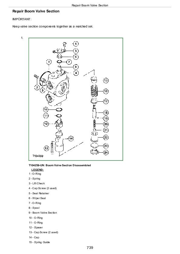
Repair Boom Valve Section
Repair Auxiliary Valve Section
Remove And Install Bucket Cylinder
Remove And Install Boom Cylinder
Disassemble And Assemble Bucket Or Boom Cylinder
Remove And Install Return Filter And Bypass Valve
Section 99: Dealer Fabricated Tools
Group 9900: Dealer Fabricated Tools
DFT1107 Hydrostatic Pump Pipe Clamp
DFT1119 Pump Support
John Deere 4WD Loader 244H Repair Service Manual (TM1629)


