John Deere 130G and 130GLC Excavator Diagnosis and Test Service Technical Manual (TM14288X19)
Catalog:
Model:
Complete Diagnosis & Tests Technical Manual with electrical wiring diagrams for John Deere 130G and 130GLC Excavator, with workshop information to maintain, diagnose, and rebuild like professional mechanics.
John Deere 130G and 130GLC Excavator workshop Diagnosis & Tests technical manual includes:
* Numbered table of contents easy to use so that you can find the information you need fast.
* Detailed sub-steps expand on repair procedure information
* Numbered instructions guide you through every repair procedure step by step.
* Troubleshooting and electrical service procedures are combined with detailed wiring diagrams for ease of use.
* Notes, cautions and warnings throughout each chapter pinpoint critical information.
* Bold figure number help you quickly match illustrations with instructions.
* Detailed illustrations, drawings and photos guide you through every procedure.
* Enlarged inset helps you identify and examine parts in detail.
TM14288X19 - John Deere 130G and 130GLC Excavator Technical Manual.pdf
tm14288x54 - John Deere Escavadeiras 130G e 130GLC.pdf
tm14288x63 - John Deere Excavadora 130G y 130GLC.pdf
PRODUCT DETAILS:
Total Pages: 1,205 pages
File Format: PDF (bookmarked, ToC, Searchable, Printable)
Category: Operation and Test
Language: English Spanish Portuguese
Published on 2019/04/25
Models: John Deere - Excavator - 1F9130GX_ _D040001-
TABLE OF CONTENTS
Section 9000: General Information................22
Group 01: Safety................22
Recognize Safety Information................25
Follow Safety Instructions................26
Operate Only If Qualified................27
Wear Protective Equipment................28
Protect Against Noise................29
Avoid Unauthorized Machine Modifications................30
Control Pattern................31
Inspect Machine................32
Stay Clear of Moving Parts................33
Avoid High-Pressure Fluids................34
Avoid High-Pressure Oils................35
Work In Ventilated Area................36
Avoid Static Electricity Risk When Refueling................37
High Debris Applications................38
Prevent Fires................39
In Case of Machine Fire................40
Prevent Battery Explosions................41
Handle Chemical Products Safely................42
Handle Starting Fluid Safely................43
Decommissioning — Proper Recycling and Disposal of Fluids and Components................44
Prepare for Emergencies................45
Clean Debris from Machine................46
Add Cab Guarding for Special Uses................47
Use Steps and Handholds Correctly................48
Start Only From Operator's Seat................49
Use and Maintain Seat Belt................50
Heated and Ventilated Operator’s Seat................51
Prevent Unintended Machine Movement................52
Avoid Work Site Hazards................53
Keep Riders Off Machine................55
Avoid Backover Accidents................56
Avoid Machine Tip Over and Machine Damage................57
Use Special Care When Lifting Objects................59
Use Care When Swinging Machine................60
Operate Boom With Care................61
Avoid Power Lines................62
Use Special Care When Operating................63
Inspect and Maintain ROPS................64
Travel Safely................65
Prevent Acid Burns................66
Add and Operate Attachments Safely................68
Park and Prepare for Service Safely................69
Service Machines Safely................70
Service Cooling System Safely................71
Remove Paint Before Welding or Heating................72
Make Welding Repairs Safely................73
Drive Metal Pins Safely................74
Use Proper Lifting Equipment................75
Section 9001: Diagnostics................76
Group 10: Main Controller (MCZ) Diagnostic Trouble Codes................82
Main Controller (MCZ) Diagnostic Trouble Codes................82
Controller Area Network 0 (CAN 0) Circuit Diagnostics................83
Controller Area Network 1 (CAN 1) Circuit Diagnostics................84
Interface Controller Area Network (N-CAN) Diagnostics................85
011000.02 - Abnormal EEPROM................76
011001.02 - Abnormal RAM................76
011002.02 - Abnormal A/D Converter................76
011003.03 - Abnormal Sensor Voltage................76
011006.02 - Engine Controller Communication Error................76
011007.02 - (CAN 0) Data Converter Communication Error 1................76
011008.02 - (CAN 1) Data Converter Communication Error 2................76
011009.02 - (CAN 0) Monitor Controller Communication Error 1................76
011010.02 - (CAN 1) Monitor Controller Communication Error 2................76
011100.02 - Abnormal Engine Speed................76
011101.03 - Engine Speed Dial Sensor Circuit High Input................76
011101.04 - Engine Speed Dial Sensor Circuit Low Input................76
011200.03 - Pump 1 Delivery Pressure Sensor Circuit High Input................76
011200.04 - Pump 1 Delivery Pressure Sensor Circuit Low Input................76
011202.03 - Pump 2 Delivery Pressure Sensor Circuit High Input................76
011202.04 - Pump 2 Delivery Pressure Sensor Circuit Low Input................76
011206.03 - Pump 1 Flow Control Pressure Sensor Circuit High Input................76
011206.04 - Pump 1 Flow Control Pressure Sensor Circuit Low Input................76
011208.03 - Pump 2 Flow Control Pressure Sensor Circuit High Input................76
011208.04 - Pump 2 Flow Control Pressure Sensor Circuit Low Input................76
011301.03 - Swing Pilot Pressure Sensor Circuit High Input................76
011301.04 - Swing Pilot Pressure Sensor Circuit Low Input................76
011302.03 - Boom Up Pilot Pressure Sensor Circuit High Input................76
011302.04 - Boom Up Pilot Pressure Sensor Circuit Low Input................76
011303.03 - Arm Roll-in Pilot Pressure Sensor Circuit High Input................76
011303.04 - Arm Roll-in Pilot Pressure Sensor Circuit Low Input................76
011304.03 - Travel Pilot Pressure Sensor Circuit High Input................76
011304.04 - Travel Pilot Pressure Sensor Circuit Low Input................77
011307.03 - Front Attachment Pilot Pressure Sensor Circuit High Input................77
011307.04 - Front Attachment Pilot Pressure Sensor Circuit Low Input................77
011400.02 - Pump 2 Flow Rate Limit Solenoid Feedback Abnormal................77
011400.03 - Pump 2 Flow Rate Limit Solenoid Feedback High Current................77
011400.04 - Pump 2 Flow Rate Limit Solenoid Feedback Low Current................77
011401.02 - Torque Control Solenoid Abnormal Feedback................77
011401.03 - Torque Control Solenoid Feedback High Current................77
011401.04 - Torque Control Solenoid Feedback Low Current................77
011402.02 - Dig Regenerative Solenoid Feedback Current Abnormal................77
011402.03 - Dig Regenerative Solenoid Feedback Current High................77
011402.04 - Dig Regenerative Solenoid Feedback Current Low................77
011403.02 - Arm Regenerative Solenoid Feedback Current Abnormal................77
011403.03 - Arm Regenerative Solenoid Feedback Current High................77
011403.04 - Arm Regenerative Solenoid Feedback Current Low................77
011407.02 - Power Boost/Travel Speed Solenoid Feedback Current Abnormal................77
011407.03 - Power Boost/Travel Speed Solenoid Feedback Current High................77
011407.04 - Power Boost/Travel Speed Solenoid Feedback Current Low................77
011408.02 - 2-Spool Solenoid Valve Unit (SJ) Abnormal Feedback................77
011408.03 - 2-Spool Solenoid Valve Unit (SJ) Feedback High Input................77
011408.04 - 2-Spool Solenoid Valve Unit (SJ) Feedback Low Input................77
011409.02 - 2-Spool Solenoid Valve Unit (SZ) Abnormal Feedback................77
011409.03 - 2-Spool Solenoid Valve Unit (SZ) Feedback High Input................77
011409.04 - 2-Spool Solenoid Valve Unit (SZ) Feedback Low Input................77
011428.02 - Arm 2 Flow Rate Control Solenoid Valve Feedback Abnormal................77
011428.03 - Arm 2 Flow Control Solenoid Valve Feedback High Input................77
011428.04 - Arm 2 Flow Control Solenoid Valve Feedback Low Input................77
011434.02 - Attachment Relief 1 (Upper) Proportional Solenoid Valve Abnormal Feedback................77
011434.03 - Attachment Relief 1 (Upper) Proportional Solenoid Valve Feedback High Current................77
011434.04 - Attachment Relief 1 (Upper) Proportional Solenoid Valve Feedback Low Current................77
011435.02 - Attachment Relief 2 (Lower) Proportional Solenoid Valve Abnormal Feedback................77
011435.03 - Attachment Relief 2 (Lower) Proportional Solenoid Valve Feedback High Current................77
011435.04 - Attachment Relief 2 (Lower) Proportional Solenoid Valve Feedback Low Current................77
011436.02 - Breaker Relief Proportional Solenoid Valve Abnormal Feedback................78
011436.03 - Breaker Relief Proportional Solenoid Valve Feedback High Current................78
011436.04 - Breaker Relief Proportional Solenoid Valve Feedback Low Current................78
011457.02 - 2-Speed Activation Solenoid Disconnected or Not Present................78
011458.02 - Selector Valve Solenoid Valve Disconnected or Not Present................78
011459.02 - Idle Stop Relay Circuit Malfunction................78
011810.03 - Electrical Lever Control Pressure 1 Sensor High Input................78
011810.04 - Electrical Lever Control Pressure 1 Sensor Low Input................78
011901.03 - Hydraulic Oil Temperature Sensor Circuit High Input................78
011901.04 - Hydraulic Oil Temperature Sensor Circuit Low Input................78
020010.02 - Abnormal Exhaust Filter................78
020062.02 - Hydraulic Oil Temperature Alarm................78
Group 20: Engine Control Unit (ECU) Diagnostic Trouble Codes................251
Engine Control Unit (ECU) Diagnostic Trouble Codes................251
000158.01 - System Voltage Low................78
000647.05 - Variable Speed Fan Solenoid Open Circuit................78
000647.31 - Variable Speed Fan Solenoid Short Circuit................78
000898.09 - Engine Speed Request Not Received or Timed Out................78
001075.05 - Low-Pressure Fuel Pump Circuit has High Resistance................78
001638.09 - Hydraulic Oil Temperature Message Not Received or Timed Out................78
Group 30: Monitor Controller (DSZ) Diagnostic Trouble Codes................260
Monitor Controller (DSZ) Diagnostic Trouble Codes................260
013000.02 - Flash Memory Failure 1................78
013001.02 - Flash Memory Failure 2................78
013002.02 - ECU Communication Error................78
013003.02 - Main Controller (MCZ) Communication Error 1................78
013004.02 - Main Controller (MCZ) Communication Error 2................78
013005.02 - Monitor Controller (DSZ) Communication Error 1................78
013006.02 - Monitor Controller (DSZ) Communication Error 2................78
013007.02 - Machine Controller (BCZ) Communication Error................78
Group 40: Information Controller (ICZ) Diagnostic Trouble Codes................270
Information Controller (ICZ) Diagnostic Trouble Codes................270
013303.02 - Abnormal Monitor Internal Temperature Sensor................78
013304.02 - Alternator Alarm................79
013305.02 - Abnormal Manual Glow EXT Output................79
013310.03 - Coolant Temperature Sensor Short Circuit................79
013311.03 - Fuel Level Sensor Open Circuit................79
013311.04 - Fuel Level Sensor Shorted Circuit................79
013334.02 - Radiator Coolant Error................79
014001.02 - Flash Memory Read/Write Error................79
014002.02 - External RAM Read/Write Error................79
014003.02 - Abnormal EEPROM................79
014006.02 - Communication Terminal: Communication Error................79
014008.02 - Abnormal Internal RAM................79
014009.02 - CAN Communication Error 2................79
014021.02 - Communication Terminal Security Error................79
014022.02 - SIM Card Error................79
014023.02 - Security Error................79
020100.02 - Overheat Alarm................79
020101.02 - Engine Warning Alarm................79
020102.02 - Engine Oil Pressure Alarm................79
020103.02 - Alternator Alarm................79
020105.02 - Hydraulic Oil Filter Restriction Alarm................79
020106.02 - Air Cleaner Restriction Alarm................79
020107.02 - Water Separator Alarm................79
020109.02 - Pilot Control Shutoff Lever Alarm................79
020110.02 - Fuel Filter Restriction Alarm................79
020113.02 - System Error Alarm................79
020114.02 - Overheat Alarm (Immediately After the Key is Turned ON)................79
020133.02 - Crane Function Alarm................79
020135.02 - Exhaust Filter Regeneration Unnecessary Warning................79
020137.02 - Exhaust Filter Alarm................79
020141.02 - Exhaust Temperature Alarm................79
020142.02 - Intake Air Temperature Alarm................79
020145.02 - Boost Temperature Increase Alarm................79
020146.02 - Fuel Temperature Increase Alarm................79
020149.02 - EGR Gas Temperature Alarm................80
020150.02 - Coolant Level Alarm................80
020151.02 - Engine Warning Alarm................80
020152.02 - Engine Oil Pressure Alarm................80
020153.02 - Air Cleaner Restriction Alarm................80
020154.02 - Fuel Filter Restriction Alarm................80
020155.02 - Engine Output Reduction Alarm................80
020156.02 - Cooling Performance Decrease Alarm................80
020157.02 - Cooling Performance Decrease Alarm................80
Group 50: Air Conditioner Controller (ACF) Diagnostic Trouble Codes................321
Air Conditioner Controller (ACF) Diagnostic Trouble Codes................321
11 - Open Circuit in Air Recirculation Sensor................80
12 - Short-Circuited Air Recirculation Sensor................80
13 - Open Circuit in Ambient Air Temperature Sensor................80
14 - Short-Circuited Ambient Air Temperature Sensor................80
18 - Short-Circuited Solar Radiation Sensor................80
21 - Open Circuit in Air Conditioner Freeze Control Switch................80
22 - Short-Circuited Air Conditioner Freeze Control Switch................80
43 - Abnormal Air Conditioner and Heater Blower Port Change Servomotor................80
44 - Abnormal Air Conditioner and Heater Mixer Servomotor................80
51 - Abnormal High/Low Refrigerant Pressure................80
91 - Communication Error................80
92 - CAN Bus Off Error................80
Section 9005: Operational Checkout Procedure................354
Group 10: Operational Checkout Procedure................354
Operational Checkout................417
Section 9010: Engine................479
Group 05: Theory of Operation................695
Engine Identification................483
John Deere Engine................501
Engine Fuel System Component Location................487
Engine Cooling System Component Location................488
Cold Weather Starting Aid................489
Engine Speed Control System Operation................695
Group 15: Diagnostic Information................479
John Deere Engine................501
Group 20: Adjustments................479
John Deere Engine................501
Group 25: Tests................479
John Deere Engine................501
Section 9015: Electrical System................502
Group 05: System Information................502
Electrical Diagram Information................514
Group 10: System Diagrams................502
Explanation of Wire Markings................523
Fuse and Relay Specifications................524
System Functional Schematic, Component Location, and Wiring Diagram Master Legend................528
System Functional Schematic................535
Cab Harness (W1) Component Location................542
Cab Harness (W1) Wiring Diagram................546
Machine Harness (W2) Component Location................551
Machine Harness (W2) Wiring Diagram................553
Monitor Harness (W3) Component Location................555
Monitor Harness (W3) Wiring Diagram................556
Engine Harness (W4) Component Location................558
Engine Harness (W4) Wiring Diagram................561
Engine Interface Harness (W5) Component Location................563
Engine Interface Harness (W5) Wiring Diagram................564
Pump Harness (W8) Component Location................566
Pump Harness (W8) Wiring Diagram................568
Pilot Shutoff Switch Harness (W11) Component Location................570
Pilot Shutoff Switch Harness (W11) Wiring Diagram................571
Heated Air Seat Harness (W14) Component Location................572
Heated Air Seat Harness (W14) Wiring Diagram................574
Multi-Function Pilot Control Lever Harness (W15) Component Location................575
Multi-Function Pilot Control Lever Harness (W15) Wiring Diagram................577
Travel Alarm Cancel Switch Harness (W16) Component Location................578
Travel Alarm Cancel Switch Harness (W16) Wiring Diagram................579
Attachment Harness (W17) Component Location................580
Attachment Harness (W17) Wiring Diagram................581
Alternator Harness (W18) Component Location................582
Alternator Harness (W18) Wiring Diagram................583
Rear Camera Harness (W19) Component Location................584
Rear Camera Harness (W19) Wiring Diagram................585
Alternator Jumper Harness (W20) Component Location................586
Alternator Jumper Harness (W20) Wiring Diagram................587
Pilot Shutoff Valve Harness (W21) Component Location................588
Pilot Shutoff Valve Harness (W21) Wiring Diagram................589
Auxiliary 3-Button Cancel Switch Harness (W22) Component Location................590
Auxiliary 3-Button Cancel Switch Harness (W22) Wiring Diagram................591
Travel Alarm Harness (W26) Component Location................592
Travel Alarm Harness (W26) Wiring Diagram................593
Starter Harness (W27) Component Location................594
Starter Harness (W27) Wiring Diagram................595
Starter Switch Harness (W29) Component Location................597
Starter Switch Harness (W29) Wiring Diagram................598
Attachment Pressure Sensor Harness (W31) Component Location................599
Attachment Pressure Sensor Harness (W31) Wiring Diagram................600
2-Speed Harness (W32) Component Location—If Equipped................601
2-Speed Harness (W32) Wiring Diagram—If Equipped................603
Fuel Injector Harness (W38) Component Location................605
Fuel Injector Harness (W38) Wiring Diagram................606
Heater and Air Conditioner Harness (W41) Component Location................608
Heater and Air Conditioner Harness (W41) Wiring Diagram................609
Starter Protection Jumper Harness (W42) Component Location................610
Starter Protection Jumper Harness (W42) Wiring Diagram................611
Cab Roof Light Harness (W44) Component Location................612
Cab Roof Light Harness (W44) Wiring Diagram................613
Cab Roof Light Jumper Harness (W45) Component Location................614
Cab Roof Light Jumper Harness (W45) Wiring Diagram................615
Cab Roof Light 1 Relay Harness (W46) Component Location................616
Cab Roof Light 1 Relay Harness (W46) Wiring Diagram................617
Cab Roof Light 2 Relay Harness (W47) Component Location................618
Cab Roof Light 2 Relay Harness (W47) Wiring Diagram................619
Heater and Air Conditioner Relay Harness (W51) Component Location................620
Heater and Air Conditioner Relay Harness (W51) Wiring Diagram................621
Auxiliary Solenoid Harness (W61) Component Location................623
Auxiliary Solenoid Harness (W61) Wiring Diagram................625
Modular Telematics Gateway (MTG) Harness (W6002) Component Location................627
Modular Telematics Gateway (MTG) Harness (W6002) Wiring Diagram................628
Satellite (SAT) Harness (W6003) Component Location................629
Satellite (SAT) Harness (W6003) Wiring Diagram................630
Group 15: Sub-System Diagnostics................504
Controller Area Network (CAN) Circuit Theory of Operation................695
Starting and Charging Circuit Theory of Operation................695
Monitor Controller (DSZ) Circuit Theory of Operation................695
Engine Control Unit (ECU) Circuit Theory of Operation................695
Main Controller (MCZ) Circuit Theory of Operation................695
Machine Controller (BCZ) Circuit Theory of Operation................695
Windshield Wiper and Washer Circuit Theory of Operation................695
Lighting Circuit Theory of Operation................695
Travel Alarm Circuit Theory of Operation................695
Pilot Shutoff Circuit Theory of Operation................695
Attachment Control Circuit Theory of Operation................695
Group 16: Monitor Operation................695
Service Menu................684
Troubleshooting................685
Monitoring................686
Controller Version................693
Issued Warning Record................694
Operation................695
Machine Setting................696
Monitor Setting................703
Maintenance Mode................706
Rear View Camera Troubleshooting................707
Group 20: References................504
Reading Diagnostic Trouble Codes with Monitor Display................711
Service ADVISOR™ Diagnostic Application................712
Service ADVISOR™ Connection Procedure................713
Reading Diagnostic Trouble Codes with Service ADVISOR™ Diagnostic Application................715
MPDr Application................718
MPDr Connection Procedure................719
Controller Area Network (CAN) Circuit Test................721
Electrical Component Specifications................727
Alternator Test................730
Electrical Component Checks................732
Battery Remove and Install................740
Rear Cover Remove and Install................742
Main Controller (MCZ) Remove and Install................744
Machine Controller (BCZ) Remove and Install................746
Engine Control Unit (ECU) Remove and Install................749
Data Converter Remove and Install................751
Monitor Controller (DSZ) Remove and Install................752
Air Conditioner Controller (ACF) Remove and Install................754
Key Switch Remove and Install................755
Right Switch Console Remove and Install................756
Left Switch Console Remove and Install................758
Travel Alarm Remove and Install................760
Section 9020: Power Train................761
Group 05: Theory of Operation................695
Track Adjuster and Recoil Spring Operation................764
Travel Gear Case Operation................766
Group 15: Diagnostic Information................761
Noisy or Loose Track Chain................761
Tight Track Chain................761
Frequent Track Chain Sag Adjustment Required................761
Excessive Oil Leakage From Front Idler, Track Rollers, or Carrier Rollers................761
Bent Track Shoes................761
“Popping” of Track................761
Cracked Track Link................761
Chipped Link Rails................761
Individual Undercarriage Component Wear................761
Measure Swing Bearing Wear................783
Section 9025: Hydraulic System................787
Group 05: Theory of Operation................695
Hydraulic System Operation................792
Pilot System Operation................793
Pilot Pump, Pressure Regulating Valve, and Filter Operation................794
Pilot Shutoff Solenoid Valve Operation................796
Pilot Control Valve Operation................828
Travel Pilot Control Valve Operation................828
Pilot Operation of Control Valve Operation................828
Pilot Signal Manifold Operation................807
Pump 1, Pump 2, and Drive Gear Case Operation................815
Pump 1 and Pump 2 Regulator Operation................818
Engine Speed Sensing Control Circuit Operation................826
Control Valve Operation................828
Control Valve Check Valves Identification and Operation................840
Main Relief Valve Circuit Operation................844
Circuit Relief and Anticavitation Valve Operation................848
Travel Flow Combiner Valve Operation................850
Auxiliary Flow Combiner Valve and Bypass Shutoff Valve Operation................854
Boom Lower Meter-In Cut Valve Operation................859
Boom Regenerative Valve Circuit Operation................862
Dig Regenerative Valve Circuit Operation................864
Arm Regenerative Valve Circuit Operation................870
Bucket Regenerative Valve Circuit Operation................875
Boom and Arm Reduced Leakage Valves Operation................877
Arm 1 Flow Rate Control Valve Circuit Operation................880
Arm 2 Flow Rate Control Valve Circuit Operation................885
Bucket Flow Rate Control Valve Circuit Operation................890
Boom Flow Rate Control Valve Circuit Operation................896
Auxiliary Flow Rate Control Valve Circuit Operation................902
Swing Reduction Gear Case Operation................908
Swing Motor, Crossover Relief Valve, and Make-Up Check Valve Operation................909
Swing Motor Park Brake Release Circuit Operation................912
Center Joint Operation................914
Travel Motor and Park Brake Valve Operation................916
Travel Motor Speed Circuit Operation................922
Cylinder Operation................926
Return Filter Operation................928
Auxiliary System Operation................929
Auxiliary Pilot Control Valve Operation................930
Flow Rate Select Solenoid Valve Operation................935
Flow Rate Pressure Reducing Valve Operation................937
Selector Valve Solenoid Valve Operation................938
Selector Valve Operation................939
Auxiliary Shuttle Valve Operation................940
Auxiliary High Flow Line Kit Operation................942
Two Way Solenoid Kit Operation................945
Two Pump Combined Flow Kit Operation................948
Group 15: Diagnostic Information................788
All Hydraulic Functions Slow................788
Hydraulic Oil Overheats................788
No Hydraulic Functions................788
No Hydraulic Functions—Electrical Checks................788
Function Does Not Stop When Control Lever Released................788
Load Drifts Down When Control Lever is in Neutral Position................788
Load Falls When Control Valve is Actuated to Raise Load................788
H/P (High Power) Function Does Not Operate, PWR (Power) Mode is Normal................788
Boom Down Does Not Function, Moves Slowly, or is Erratic, All Other Functions Normal................788
Arm In Does Not Function, Moves Slowly, or is Erratic, All Other Functions Normal................788
Swing Speed Slow During Arm In Function................788
Boom Cannot Raise Track Off Ground................788
Swing Function Does Not Operate in Both Directions................788
Swing Speed Slow in Both Directions................788
Swing Speed Slow or Does Not Operate in One Direction................788
Upperstructure Drift with Swing Valve in Neutral................788
Machine Freewheels Down an Incline................788
Track Will Not Move in Either Direction................789
Machine Mistracks................789
Machine Mistracks Left During Combined Travel and Dig Functions................789
Machine Will Not Shift Into Fast (rabbit) Speed................789
Pump 1, Pump 2, and Pilot Pump Line Identification................1015
Control Valve Line Identification................1017
Swing Motor Line Identification................1020
Pilot Control Valve-to-Pilot Signal Manifold Component Location—Excavator Pattern................1022
Pilot Control Valve-to-Pilot Signal Manifold Component Location—Backhoe Pattern................1024
Pilot Signal Manifold-to-Control Valve Line Connection................1026
Travel System Component Location................1029
Travel Hydraulic System Line Connection................1031
Auxiliary Attachment Schematic................1033
Auxiliary System Line Connections................1038
Hydraulic System Schematic................1040
Hydraulic System Component Location................1049
Hydraulic System Line Connections................1051
Group 25: Tests................789
JT05800 Digital Thermometer Installation................1053
JT02156A Digital Pressure and Temperature Analyzer Kit Installation................1054
General Hydraulic Oil Cleanup Procedure................1055
Hydraulic Component Failure Cleanup Procedure................1058
Hydraulic Oil Tank Pressure Release Procedure................1061
Hydraulic Oil Warm-Up Procedure................1062
Pilot Pressure Regulating Valve Test and Adjustment................1065
Control Valve Spool Actuating Pilot Pressure Test................1069
Dig Regenerative Solenoid Valve Test and Adjustment................1072
Arm Regenerative Solenoid Valve Test and Adjustment................1077
Power Dig/Travel Speed Solenoid Valve Test and Adjustment................1082
Arm 2 Flow Control Solenoid Valve Test and Adjustment................1087
Torque Control Solenoid Valve Test and Adjustment................1092
Pump Control Pilot Pressure Signal Test................1097
Main Relief and Power Dig Valve Test and Adjustment................1100
Circuit Relief Valve Test and Adjustment................1107
Swing Motor Crossover Relief Valve Test and Adjustment................1113
Travel Motor Crossover Relief Valve Test and Adjustment................1117
Pump Regulator Test and Adjustment—Minimum Flow................1123
Pump Regulator Test and Adjustment—Maximum Flow................1127
Pump Flow Test................1130
Comprehensive Pump Flow Test................1134
Swing Motor Leakage Test................1140
Travel Motor Leakage Test................1143
Cylinder Drift Test—Boom, Arm, and Bucket................1147
Upperstructure Drift Test................1150
Section 9031: Heating and Air Conditioning................1153
Group 05: Theory of Operation................695
Air Conditioning System Cycle of Operation................1156
Group 15: Diagnostic Information................1153
Air Conditioning System Does Not Operate................1153
Air Conditioning System Does Not Cool Interior of Cab................1153
Air Conditioning System Runs Constantly, Too Cold................1153
Heating System Does Not Operate................1153
Heating System Does Not Warm Interior of Cab................1153
Interior Windows Continue to Fog................1153
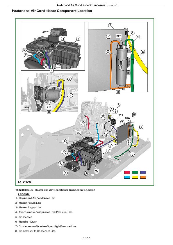
Heater and Air Conditioner Component Location................1180
Group 25: Tests................1153
R134a Refrigerant Cautions and Proper Handling................1183
R134a Oil Charge Capacity................1184
R134a Refrigerant Charge Capacity................1185
Heater and Air Conditioner Operational Checks................1186
Air Conditioner Compressor Clutch Test................1189
R134a Refrigerant Leak Test................1190
R134a Refrigerant Hoses and Tubing Inspection................1191
Air Conditioner High/Low-Pressure Switch Test................1192
Air Conditioner Freeze Control Switch Test................1195
Air Conditioner Compressor Belt Check................1196
Air Conditioning System Test................1197
Operating Pressure Diagnostic Chart................1200
Section 9900: Dealer Fabricated Tools................1202
Group 99: Dealer Fabricated Tools................1202
DFT1218 Split Flange Hose Cap................1204
John Deere 130G and 130GLC Excavator Diagnosis and Test Service Technical Manual (TM14288X19)


