John Deere 210L EP Repair Service Manual (TM13476X19)
Catalog:
Model:
Complete Repair Service Technical Manual for John Deere 210L EP Tractor Loader, with all the workshop information to maintain, repair, and rebuild like professional mechanics.
John Deere 210L EP Tractor Loader workshop technical manual (repair) includes:
* Numbered table of contents easy to use so that you can find the information you need fast.
* Detailed sub-steps expand on repair procedure information
* Numbered instructions guide you through every repair procedure step by step.
* Notes, cautions and warnings throughout each chapter pinpoint critical information.
* Bold figure number help you quickly match illustrations with instructions.
* Detailed illustrations, drawings and photos guide you through every procedure.
* Enlarged inset helps you identify and examine parts in detail.
TM13476X19 - John Deere 210L EP Tractor Loader Technical Manual.pdf
tm13476x63 - John Deere 210L EP Cargadora del tractor.pdf
tm13476x28 - John Deere 210L EP Chargeur du tracteur.pdf
PRODUCT DETAILS:
Total Pages: 861 pages
File Format: PDF (bookmarked, ToC, Searchable, Printable)
Category: Repair
Language: English Spanish French
Published on 2020/03/21
Models: John Deere - Tractor Loader - 1T8210EL_ _J892600-895000
TABLE OF CONTENTS
Section 00: General Information................15
Group 0001: Safety................15
Recognize Safety Information................18
Follow Safety Instructions................19
Operate Only If Qualified................20
Wear Protective Equipment................21
Avoid Unauthorized Machine Modifications................22
Inspect Machine................23
Stay Clear of Moving Parts................24
Avoid High-Pressure Fluids................25
Avoid High-Pressure Oils................26
Work In Ventilated Area................27
Avoid Static Electricity Risk When Refueling................28
Prevent Fires................30
In Case of Machine Fire................31
Prevent Battery Explosions................32
Handle Chemical Products Safely................33
Handle Starting Fluid Safely................34
Decommissioning — Proper Recycling and Disposal of Fluids and Components................35
Prepare for Emergencies................36
Clean Debris from Machine................37
Use Steps and Handholds Correctly................38
Start Only From Operator's Seat................39
Use and Maintain Seat Belt................40
Prevent Unintended Machine Movement................41
Avoid Work Site Hazards................42
Keep Riders Off Machine................44
Avoid Backover Accidents................45
Avoid Machine Tipover................46
Operating on Slopes................47
Operating or Traveling On Public Roads................48
Inspect and Maintain ROPS................49
Travel Safely................50
Prevent Acid Burns................51
Add and Operate Attachments Safely................53
Use Special Care When Operating................54
Park and Prepare for Service Safely................55
Service Cooling System Safely................56
Remove Paint Before Welding or Heating................57
Make Welding Repairs Safely................58
Drive Metal Pins Safely................59
Service Tires Safely................60
Group 0003: Torque Values................16
Metric Bolt and Cap Screw Torque Values................63
Additional Metric Cap Screw Torque Values................65
Unified Inch Bolt and Cap Screw Torque Values................67
Service Recommendations for 37° Flare and 30° Cone Seat Connectors................69
Service Recommendations for O-Ring Boss Fittings................71
O-Ring Boss Fittings In Aluminum Housing Service Recommendations—Excavators................73
Service Recommendations for Flared Connections—Straight or Tapered Threads................76
Service Recommendations For Flat Face O-Ring Seal Fittings................78
O-Ring Face Seal Fittings With SAE Inch Hex Nut And Stud End For High Pressure Service Recommendations................80
O-Ring Face Seal Fittings With Metric Hex Nut And Stud End For Standard Pressure Service Recommendations................82
O-Ring Face Seal Fittings With Metric Hex Nut And Stud End For High Pressure Service Recommendations................85
Service Recommendations for Metric Series Four Bolt Flange Fitting................88
Service Recommendations For Inch Series Four Bolt Flange Fittings................90
Inch Series Four Bolt Flange Fitting For High Pressure Service Recommendations................92
Service Recommendations For Non-Restricted Banjo (Adjustable) Fittings................94
Service Recommendations For O-Ring Boss Fittings With Shoulder................97
Metric 24° O-Ring Seal DIN 20078 Service Recommendations................100
Section 01: Wheels................104
Group 0110: Powered or Non-Powered Wheels and Fastenings................104
Rear Wheel Assembly Remove and Install................108
Front Wheel Assembly Remove and Install................111
Tire Remove and Install................113
Section 02: Axles and Suspension Systems................117
Group 0225: Input Drive Shafts and U-Joints................117
Universal Joint and Drive Shaft Remove and Install................123
Group 0240: Powered Wheel Axle (MFWD)................117
Mechanical Front Wheel Drive (MFWD) Axle Remove and Install................131
Mechanical Front Wheel Drive (MFWD) Axle Disassemble................134
Mechanical Front Wheel Drive (MFWD) Axle Assemble................152
Open Differential Disassemble and Assemble................185
Limited Slip Differential Disassemble and Assemble................193
Group 0250: Axle Shaft, Bearings, and Reduction Gears................117
Service Brakes Inspection................207
Rear Axle Remove and Install................210
Rear Axle Disassemble................213
Rear Axle Assemble................230
Park Brake Disassemble and Assemble................256
Gear Tooth Contact Pattern Check................276
Section 03: Transmission................279
Group 0300: Removal and Installation................279
Transmission Remove and Install................292
Group 0350: Gear, Shafts, and Power Shift Clutches................279
Transmission Outer Components Removal................309
Transmission Outer Components Install................314
Transmission Case Disassemble—Torque Converter Side................319
Transmission Case Assemble—Torque Converter Side................323
Clutch Packs Remove................328
Clutch Packs Install................334
High Range Forward, Low Range Forward, and Reverse Clutch Packs Disassemble and Assemble................340
First Speed Disassemble and Assemble................360
Second Speed Clutch Disassemble and Assemble................377
Mechanical Front Wheel Drive (MFWD) Clutch Disassemble and Assemble................392
Pump Drive Shaft Install................404
Group 0360: Hydraulic System................279
Transmission Charge Pump Remove and Install................412
Transmission Charge Pump Disassemble and Assemble................418
Section 04: Engine................420
Group 0400: Removal and Installation................420
John Deere Engine Operation................423
Engine Remove and Install................425
Section 05: Engine Auxiliary System................432
Group 0510: Cooling Systems................432
Fan Remove and Install................435
Accessory Drive Belt Remove and Install................437
Radiator Remove and Install................440
Cooling Package Remove and Install................441
Cooling Package Disassemble and Assemble................444
Group 0520: Intake System................432
Air Cleaner Remove and Install................450
Charge Air Cooler Remove and Install................451
Group 0530: Exhaust Systems................432
Muffler Remove and Install................453
Group 0560: External Fuel Supply Systems................432
Fuel Tank Remove and Install................456
Section 06: Torque Converter................458
Group 0651: Turbine, Gears, and Shaft................458
Torque Converter Remove and Install................461
Section 09: Steering System................463
Group 0920: Power Steering................463
Fixed Steering Column Remove and Install................465
Tilt Steering Column Remove and Install................466
Steering Wheel and Column Disassemble and Assemble................468
Group 0960: Power Steering Hydraulic System................463
Steering Valve Remove and Install................473
Steering Valve Disassemble and Assemble................474
Tie Rod Remove and Install................488
Mechanical Front Wheel Drive (MFWD) Axle Steering Cylinder Remove and Install................490
Mechanical Front Wheel Drive (MFWD) Axle Steering Cylinder Disassemble and Assemble................492
Section 10: Service Brakes................494
Group 1011: Active Elements................494
Brake Disk and Pressure Plate Remove and Install................496
Group 1015: Control Linkage................494
Brake Pedal Adjustment................498
Group 1060: Hydraulic System................494
Brake System Bleeding Procedure................500
Power Boost Brake Valve Remove and Install................501
Power Boost Brake Valve Disassemble and Assemble................502
Section 11: Park Brake................509
Group 1111: Active Elements................509
Park Brake Remove and Install................511
Section 15: Equipment Attaching................512
Group 1511: Hitch, Drawbar, and Weights................512
Hitch Weight and Drawbar Remove and Install—If Equipped................516
Group 1520: 3-Point Hitch................512
3-Point Hitch Remove and Install................521
Lift Cylinder Remove and Install................523
3-Point Hitch Control Linkage Remove and Install................525
Section 16: Electrical System................529
Group 1600: Removal and Installation................529
Installation of Repair Wire Assembly (RWA)................539
Remove Connector Body from Blade Terminals................548
Electronic Controllers Remove and Install................549
CINCH™ Connector Remove and Install................550
CINCH™ Contact Installation................552
CINCH™ CP Connector Remove and Install................554
CINCH™ CP Contact Installation................564
DEUTSCH® Connector Remove and Install................568
DEUTSCH® Contact Installation................572
Metri-Pack® Connector Remove and Install................574
WEATHER PACK® Connector Remove and Install................577
WEATHER PACK® Contact Installation................579
Group 1675: System Controls................529
Transmission Control Lever (TCL) Remove and Install................583
Section 17: Frame or Supporting Structure................585
Group 1740: Frame Installation................585
Welding Repair of Major Structures................587
RIVNUT® (KREMNUT) Fasteners Remove and Install................588
Group 1749: Chassis Weights................585
Counterweight Remove and Install—If Equipped................593
Section 18: Operator's Station................595
Group 1800: Removal and Installation................595
FOPS Plate Remove and Install................598
Operator’s Station Remove and Install—Cab................599
Operator’s Station Remove and Install—Canopy................606
Group 1810: Operator Enclosure................595
Front Wiper Motor Remove and Install................613
Wiper Arm Installation................616
Front Console Remove and Install—Canopy................617
Front Console Remove and Install—Cab................623
Fixed Window Remove and Install................628
Non-Fixed Window Remove and Install................633
Cab Door Remove and Install................636
Headliner Remove and Install................640
Cab Roof Remove and Install................642
Canopy Roof Remove and Install................645
Group 1821: Seat and Seat Belt................595
Fixed Seat Remove and Install................648
Suspension Seat Remove and Install................650
Fixed Seat Disassemble and Assemble—If Equipped................653
Suspension Seat Disassemble and Assemble—If Equipped................654
Seat Belt Disassemble and Assemble................659
Group 1830: Heating and Air Conditioning................595
R134a Refrigerant Cautions and Proper Handling................661
R134a Refrigerant Oil Information................662
R134a Refrigerant Recovery, Recycling, and Charging Station Installation Procedure................664
Recover R134a Refrigerant................666
Flush and Purge Air Conditioning System................667
Evacuate R134a System................670
Charge R134a System................672
Evaporator or Heater Core Remove and Install................674
Expansion Valve Remove and Install................677
Blower Motor Resistor Remove and Install................680
Air Conditioner Freeze Control Switch Remove and Install................681
Receiver-Dryer Remove and Install................683
Condenser Remove and Install................684
Compressor Remove and Install................685
Section 19: Sheet Metal and Styling................688
Group 1910: Hood or Engine Enclosure................688
Hood and Engine Enclosure Remove and Install................691
Group 1913: Miscellaneous Shields................688
Battery Box Remove and Install................696
Group 1921: Grille and Grille Housing................688
Grille Remove and Install................701
Section 21: Main Hydraulic System................703
Group 2100: Removal and Installation................703
Hydraulic Pump Remove and Install................707
Hydraulic Reservoir Remove and Install................710
Hydraulic and Transmission Oil Coolers Remove and Install................717
Hydraulic Oil Filter Assembly Remove and Install................723
Main Control Valve Remove and Install................727
Main Control Valve Relief Valves Remove and Install................730
Group 2160: Hydraulic System................703
General Oil Cleanup Procedure................734
Hydraulic Component Failure Cleanup Procedure................736
Apply Vacuum to Hydraulic Oil Reservoir................738
Group 2161: Hydraulic Pumps and Drives................703
Hydraulic Pump Disassemble and Assemble................741
Group 2162: Hydraulic Selective Control and Load Holding Valves................703
Main Control Valve Disassemble and Assemble................747
Anticavitation Check Valve Disassemble and Assemble................751
Relief Valve Disassemble and Assemble................753
Relief Valve with Anticavitation Disassemble and Assemble................755
System Relief Valve Disassemble and Assemble................758
Inlet Section Disassemble and Assemble................760
Priority Section Disassemble and Assemble................763
Loader Auxiliary Section Disassemble and Assemble—Manual................766
Loader Auxiliary Section Disassemble and Assemble—Electrohydraulic................770
Bucket Section Disassemble and Assemble................774
Boom Section Disassemble and Assemble................778
Hitch Flow Control Section Disassemble and Assemble................781
Hitch Lift Section Disassemble and Assemble................784
Pitch Section Disassemble and Assemble................787
Section 31: Loader................791
Group 3102: Bucket................791
Bucket Remove and Install................794
Bolt-On Cutting Edges Remove and Install................796
Cracked Cutting Edge Repair................797
Group 3104: Attachment Coupler................791
Attachment Coupler Remove and Install................800
Attachment Coupler Cylinder Remove and Install................802
Attachment Coupler Cylinder Disassemble and Assemble................804
Attachment Coupler Manifold Remove and Install................805
Attachment Coupler Manifold Disassemble and Assemble................807
Group 3115: Control Linkage................791
Loader Control Valve Linkage Remove and Install—Single Lever................813
Loader Control Valve Linkage Remove and Install—Two Lever................817
Group 3140: Frames................791
Boom Remove and Install................825
Bucket Linkage Remove and Install................829
Group 3160: Hydraulic System................791
Boom Cylinder Remove and Install................833
Bucket Cylinder Remove and Install................835
Loader Cylinders Disassemble and Assemble................838
Loader Auxiliary Manifold Remove and Install—If Equipped................839
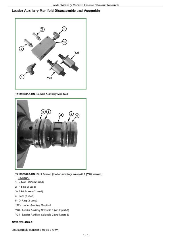
Loader Auxiliary Manifold Disassemble and Assemble................843
Ride Control Valve Remove and Install................845
Ride Control Valve Disassemble and Assemble................847
Ride Control Accumulator Remove and Install................849
Section 99: Dealer Fabricated Tools................851
Group 9900: Dealer Fabricated Tools................851
DFT1163 MFWD Snap Ring Removal and Installation Tool................853
DFT1286 Backlash Measurement Tool................854
DFT1288 Engine Support Bracket................855
John Deere 210L EP Repair Service Manual (TM13476X19)


