John Deere Compact Excavator 50ZTS Operation and Test Service Manual (TM1817)
Catalog:
Model:
Complete Diagnostics, Operation and Test manual with Electrical Wiring Diagrams for John Deere Compact Excavator 50ZTS, with all the workshop information to maintain, diagnose, and rebuild like professional mechanics.
John Deere Compact Excavator 50 ZTS workshop Diagnosis, Operation and Test manual includes:
* Numbered table of contents easy to use so that you can find the information you need fast.
* Detailed sub-steps expand on repair procedure information
* Numbered instructions guide you through every repair procedure step by step.
* Troubleshooting and electrical service procedures are combined with detailed wiring diagrams for ease of use.
* Notes, cautions and warnings throughout each chapter pinpoint critical information.
* Bold figure number help you quickly match illustrations with instructions.
* Detailed illustrations, drawings and photos guide you through every procedure.
* Enlarged inset helps you identify and examine parts in detail.
TM1817 - John Deere 50ZTS Compact Excavator Technical Manual - Operation and Test.PDF
Total Pages: 668 pages
File Format: PDF (bookmarked, ToC, Searchable, Printable, high quality)
Language: English
MAIN SECTIONS
Foreword
Technical Information Feedback Form
General Information
Safety
General Specifications
Torque Values
Fuels and Lubricants
Operational Checkout Procedure
Operational Checkout Procedure
Engine
Theory of Operation
System Operational Checks
Diagnostic Information
Adjustments
Tests
Electrical System
System Information
System Diagrams
Sub-System Diagnostics
References
Power Train
Theory of Operation
Diagnostic Information
Adjustments
Hydraulic System
Theory of Operation
Diagnostic Information
Adjustments
Tests
tm1817 - 50ZTS Excavator
Table of Contents
Foreword
Technical Information Feedback Form
Section 9000: General Information
Group 01: Safety
Follow Safe Procedures
Prepare for Emergencies
Handle Fluids Safely—Avoid Fires
Prevent Battery Explosions
Handle Chemical Products Safely
Prevent Acid Burns
Avoid High-Pressure Fluids
Warn Others of Service Work
Park Machine Safely
Support Machine Properly
Operate Only from Operator's Seat
Stay Clear of Moving Parts
Avoid Power Lines
Use Handholds and Steps
Keep Riders Off Machine
Move and Operate Machine Safely
Wear Protective Clothing
Protect Against Flying Debris
Protect Against Noise
Illuminate Work Area Safely
Service Machines Safely
Remove Paint Before Welding or Heating
Avoid Heating Near Pressurized Fluid Lines
Beware of Exhaust Fumes
Use Proper Lifting Equipment
Service Cooling System Safely
Dispose of Waste Properly
Work in a Clean Area
Use Tools Properly
Replace Safety Signs
Live With Safety
Group 02: General Specifications
50ZTS Excavator Overview
50ZTS Excavator
50ZTS Excavator Working Ranges
50ZTS Excavator Engine Specifications
50ZTS Excavator Drain and Refill Capacities
Group 03: Torque Values
Unified Inch Bolt and Screw Torque Values
Metric Bolt and Screw Torque Values
Additional Metric Cap Screw Torque Values
Check Oil Lines and Fittings
Service Recommendations for O-Ring Boss Fittings
Service Recommendations For Flat Face O-Ring Seal Fittings
Service Recommendations for 37° Flare and 30° Cone Seat Connectors
Service Recommendations For Flared Connections—Straight or Tapered Threads
Service Recommendations For Inch Series Four Bolt Flange Fittings
Service Recommendations for Metric Series Four Bolt Flange Fitting
Group 04: Fuels and Lubricants
Diesel Fuel
Lubricity of Diesel Fuels
Low Sulfur Diesel Fuel Conditioner
Diesel Fuel Storage
Fuel Tank
Do Not Use Galvanized Containers
Diesel Engine Oil
Hydraulic Oil
Propel Gearbox Oils
Track Adjuster, Working Tool Pivot, Swing Bearing, and Swing Bearing Gear Grease
Oil Filters
Lubricant Storage
Alternative and Synthetic Lubricants
Mixing of Lubricants
Section 9005: Operational Checkout Procedure
Group 10: Operational Checkout Procedure
Operational Checkout
Section 9010: Engine
Group 05: Theory of Operation
Engine—Sectional View
Fan Drive Operation
Cooling System Operation
Engine Lubrication System Operation
Air Cleaner Operation
Fuel Supply System Operation
Fuel Injection Pump Operation
Fuel Injection Nozzle Operation
Group 10: System Operational Checks
Engine Operational Checks
Group 15: Diagnostic Information
Diagnose Engine Malfunctions
Group 20: Adjustments
JT05801 Clamp-On Electronic Tachometer Installation
Group 25: Tests
Engine Speed Check
Engine Speed Control Cable Adjustment
Check and Adjust Fuel Injection Nozzle
Check and Adjust Injection Pump Timing
Adjust Fan Belt Tension
Check and Adjust Engine Valve Lash (Clearance)
Cooling System Fill and Deaeration
Air Intake System Leakage Test
Radiator Air Flow Test
Engine Compression Pressure Test
Cooling System Test
Engine Oil Pressure Test
Section 9015: Electrical System
Group 05: System Information
Visually Inspect Electrical System
Electrical Circuit Malfunctions
High Resistance Circuit
Open Circuit
Grounded Circuit
Shorted Circuit
Multimeter
Seven Step Electrical Test Procedure
Schematic Information
Electrical Schematic Symbols
Group 10: System Diagrams
Component Identification Table
Fuse Specifications
Fuse (Blade-Type) Color Codes
Component Location Drawing Legend
Control Box Component Location
Cab Control Box Connectors Wire and Pin Location
Propel Alarm Harness Component Location
Propel Alarm Connectors Wire and Pin Location
Main Frame Harness Component Location
Main Frame Connectors Wire and Pin Location
Cab Electrical Harness Component Location
Cab Harness Connectors Wire and Pin Location
System Functional Schematic
Group 15: Sub-System Diagnostics
Power Circuit Operational Information
Power Circuit Theory of Operation
Power Circuit Schematic
Starting Circuit Operational Information
Starting Circuit Theory of Operation
Starting Circuit Schematic
Starter Operation
Charging Circuit Operational Information
Charging Circuit Theory of Operation
Charging Circuit Schematic
Monitor Controller Circuit Specifications
Monitor Controller Circuit Operational Information
Monitor Controller Circuit Theory of Operation
Monitor Controller Circuit Schematic
Engine Sensor Circuit Operational Information
Engine Sensor Circuit Theory of Operation
Engine Sensor Circuit Schematic
Pilot/Propel Circuit Operational Information
Pilot/Propel Circuit Theory of Operation
Pilot/Propel Circuit Schematic
Propel Alarm Circuit Operational Information
Propel Alarm Circuit Theory of Operation
Propel Alarm Circuit Schematic
Windshield Wiper and Washer Circuit Operational Information
Windshield Wiper and Washer Circuit Theory of Operation
Windshield Wiper and Washer Circuit Schematic
Drive and Work Lights Circuit Operational Information
Drive and Work Lights Circuit Theory of Operation
Drive and Work Lights Circuit Schematic
Accessory Circuit Operational Information
Accessory Circuits Theory of Operation
Accessory Circuit Schematic
Heater Circuit Operational Information
Heater Circuit Theory of Operation
Heater Circuit Schematic
Group 20: References
Monitor Controller and Display Connector Wiring
Battery Operation
Battery Specifications
Diagnose Battery Malfunctions
Check Battery Electrolyte Level and Terminals
Procedure for Testing Batteries
Using Booster Batteries—12 Volt System
Replacing Battery
Adding 12 or 24 Volt Accessories
Section 9020: Power Train
Group 05: Theory of Operation
Track Adjuster and Recoil Spring Operation
Propel Gearbox Operation
Group 15: Diagnostic Information
Diagnose Undercarriage Components Malfunctions
Measure Track Chain Bushing Wear
Measure Track Chain Link Wear
Measure Track Chain Pitch
Measure Track Shoe Grouser Wear
Measure Track Roller Wear
Measure Track Carrier Roller Wear
Measure Front Idler Wear
Measure Swing Bearing Wear
Group 20: Adjustments
Adjust Track Sag (Rubber Track)
Adjust Track Sag (Steel Track)
Section 9025: Hydraulic System
Group 05: Theory of Operation
Hydraulic System Diagram
Pilot Pump Operation
Pilot Relief Valve Operation
Pilot Shut-Off Solenoid Valve and Propel Speed Change Solenoid Valve Operation
Pilot Controller Operation—Neutral
Pilot Controller Operation—Metering and Full Stroke
Propel Pilot Controller Operation
Pilot Controller Operation of Control Valve
Boom Swing Controller Operation
Auxiliary Controller Operation
Main Hydraulic Pump (P1, P2) Operation
Gear Pump (P3) Operation
Hydraulic Pump Regulator Component Operation
Main Control Valve Operation
Control Valve Circuit Schematic
Control Valve Pilot Pressure Signal Passage Operation
Control Valve Neutral and Power Passages Operation
System Relief Valve Operation
Blade and Boom Swing Anti-Cavitation Valve Operation
Circuit Relief Valve Operation
Flow Combiner Valve Operation
Boom Reduced Leakage Valve Operation
Swing Gearbox Operation
Swing Motor Operation
Swing Motor Crossover Relief Valves Operation
Swing Motor Anti-Cavitation Valves Operation
Swing Motor Park Brake Changeover Valve Operation
Rotary Manifold with Backfill Blade Function Operation
Propel Motor Operation
Propel Motor Speed Change Valve Operation
Propel Motor Counterbalance Valve Operation
Propel Motor Relief Valve Operation
Propel Motor Brake Valve Operation
Propel Motor Park Brake Operation
Backfill Blade Hydraulic System Operation
One-Way/Two-Way Valve Operation
Hydraulic Cylinder Operation
Hydraulic Oil Return Filter Operation
Hydraulic System Circuit Symbols
Controllers and Pilot Shut-Off Solenoid Valve Schematic
Control Valve Schematic
Main Pump Schematic
Swing Motor Schematic
Propel Motor Schematic
Group 15: Diagnostic Information
Diagnostic Procedure
Diagnose Hydraulic System Malfunctions
Diagnose Pilot Circuit Malfunctions
Diagnose Dig Circuit Malfunctions
Diagnose Swing Circuit Malfunctions
Diagnose Propel System Malfunctions
Diagnose Mechanically Actuated Control Valve Malfunctions
Control Lever Pattern Conversion
Pilot Controller to Pilot Shut-Off Valve Component Location—SAE Pattern
Pilot Controller to Pilot Shut-Off Valve Component Location—ISO Pattern
Backfill Blade Hydraulic System Component Location
Propel System Component Location
Main Control Valve Line Identification
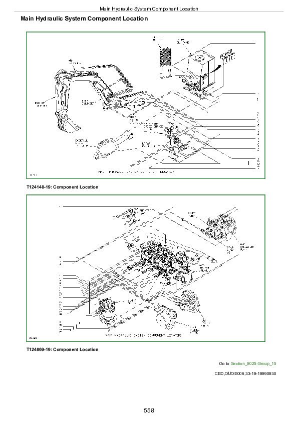
Main Hydraulic System Component Location
Pressure and Return System Component Location
Group 20: Adjustments
Adjust Blade Control Lever
Adjust Boom Swing and Auxiliary Linkage
Group 25: Tests
JT05801 Clamp-On Electronic Tachometer Installation
JT05800 Digital Thermometer Installation
JT02156A Digital Pressure/Temperature Analyzer Installation
Hydraulic Pump Start-Up Procedure
Swing Motor Start-Up Procedure
Swing Gearbox Start-Up Procedure
Propel Motor Start-Up Procedure
Propel Gearbox Start-Up Procedure
Hydraulic System Warm-Up Procedure
Lower Boom With Engine Stopped
Cycle Time Test
Swing Dynamic Braking (Drift) Test
Pilot Pressure Regulating Valve Test and Adjustment
Control Valve Spool Pilot Actuation Pressure Test (Secondary Pilot Pressure)
Pumps 1 and 2 System Relief Valve Test and Adjustment
Pump 3 System Relief Valve Test and Adjustment
Circuit Relief Valve Test and Adjustment
Swing Motor Crossover Relief Valve Test and Adjustment
Propel Motor Crossover Relief Valve Test and Adjustment
Main Hydraulic Pump Regulator Test (Engine Pulldown)
Main Hydraulic Pumps P1 and P2 Flow Test
Gear Pump P3 Flow Test
Propel System Tracking Test
Cylinder Drift Test—Boom, Arm, and Bucket
Swing Motor Leakage Test
Propel Motor Leakage Test
John Deere Compact Excavator 50ZTS Operation and Test Service Manual (TM1817)


