John Deere Compact Excavator 50CZTS Operation and Test Service Manual (TM2056)
Catalog:
Model:
Complete Diagnostics, Operation and Test manual with Electrical Wiring Diagrams for John Deere Compact Excavator 50C ZTS, with all the shop information to maintain, diagnose, and rebuild like professional mechanics.
John Deere Compact Excavator 50C ZTS workshop Diagnostic, Operation and Test manual includes:
* Numbered table of contents easy to use so that you can find the information you need fast.
* Detailed sub-steps expand on repair procedure information
* Numbered instructions guide you through every repair procedure step by step.
* Troubleshooting and electrical service procedures are combined with detailed wiring diagrams for ease of use.
* Notes, cautions and warnings throughout each chapter pinpoint critical information.
* Bold figure number help you quickly match illustrations with instructions.
* Detailed illustrations, drawings and photos guide you through every procedure.
* Enlarged inset helps you identify and examine parts in detail.
TM2056 - John Deere 50CZTS Compact Excavator Technical Manual - Operation and Test.PDF
Total Pages: 452 pages
File Format: PDF (bookmarked, ToC, Searchable, Printable, high quality)
Language: English
MAIN SECTIONS
Foreword
Technical Information Feedback Form
General Information
Safety
Operational Checkout Procedure
Operational Checkout Procedure
Engine
Theory of Operation
Diagnostic Information
Tests
Electrical System
System Information
System Diagrams
Sub-System Diagnostics
References
Power Train
Theory of Operation
Diagnostic Information
Hydraulic System
Theory of Operation
Diagnostic Information
Tests
Heater
Theory of Operation
Diagnostic Information
Tests
Table of Contents
Foreword
Technical Information Feedback Form
Section 9000: General Information
Group 01: Safety
Recognize Safety Information
Follow Safety Instructions
Operate Only If Qualified
Wear Protective Equipment
Avoid Unauthorized Machine Modifications
Add Cab Guarding for Special Uses
Inspect Machine
Stay Clear of Moving Parts
Avoid High-Pressure Oils
Beware of Exhaust Fumes
Prevent Fires
Prevent Battery Explosions
Handle Chemical Products Safely
Dispose of Waste Properly
Prepare for Emergencies
Use Steps and Handholds Correctly
Start Only From Operator's Seat
Use and Maintain Seat Belt
Prevent Unintended Machine Movement
Avoid Work Site Hazards
Keep Riders Off Machine
Avoid Backover Accidents
Avoid Machine Tip Over
Use Special Care When Lifting Objects
Add and Operate Attachments Safely
Park and Prepare for Service Safely
Service Cooling System Safely
Remove Paint Before Welding Or Heating
Make Welding Repairs Safely
Drive Metal Pins Safely
Section 9005: Operational Checkout Procedure
Group 10: Operational Checkout Procedure
Operational Checkout
Section 9010: Engine
Group 05: Theory of Operation
Engine Component Location
Engine Cooling System Operation
Engine Lubrication System Operation
Engine Fuel System Operation
Group 15: Diagnostic Information
Diagnose Engine Malfunction
Group 25: Tests
JT05801 Clamp- On Electronic Tachometer
Engine Speed Check
Engine Speed Control Cable Adjustment
Check Fuel Injection Nozzle
Check and Adjust Injection Pump Timing
Adjust Fan Belt Tension
Check and Adjust Engine Valve Lash (Clearance)
Air Intake System Leakage Test
Radiator Air Flow Test
Engine Compression Pressure Test
Engine Oil Pressure Test
Check for Head Gasket Failures
Section 9015: Electrical System
Group 05: System Information
Electrical Diagram Information
Group 10: System Diagrams
Explanation of Wire Markings
FUSE SPECIFICATIONS
Functional Schematic and Component Location Master Legend
System Functional Schematic
Main Harness (W1) Component Location
Main Harness (W1) Wiring Diagram
Floor Harness (W2) Component Location
Floor Harness (W2) Wiring Diagram
Engine Harness (W3) Component Location
Engine Harness (W3) Wiring Diagram
Cab Harness (W5) Component Location
Cab Harness (W5) Wiring Diagram
Heater Harness (W10) Wiring Diagram
Propel Alarm Harness (W11) and Propel Alarm Cancel Switch Harness (W12) Component Location
Propel Alarm Harness (W11) and Propel Alarm Cancel Switch Harness (W12) Wire Diagram
Group 15: Sub-System Diagnostics
Starting and Charging Circuit Theory of Operation
Monitor Controller Circuit Theory of Operation
Pilot Control Shut-Off Circuit Theory of Operation
Propel Alarm Circuit Theory of Operation
Group 20: References
Fuse Test
Relay Test
Pressure Sensor Test
Solenoid Test
Temperature Sensor Test
Electrical Component Checks
Battery Remove and Install
Propel Alarm Cancel Switch Remove and Install
Key Switch Remove and Install
Monitor Controller and Display (A5) Remove and Install
Glow Plug Timer Remove and Install
Propel Alarm Controller Remove and Install
Disconnect Tab Retainer Connectors
Disconnect Spring Wire Clip Connectors
Replace DEUTSCH DEUTSCH is a trademark of the Deutsch Co. Connectors
Install DEUTSCH DEUTSCH is a trademark of the Deutsch Co. Contacts
Replace WEATHER PACK WEATHER PACK is a trademark of Packard Electric. Connector
Install WEATHER PACK WEATHER PACK is a trademark of Packard Electric. Contacts
Remove Connector Body from Blade Terminals
Section 9020: Power Train
Group 05: Theory of Operation
Track Adjuster and Recoil Spring Operation
Propel Gearbox Operation
Group 15: Diagnostic Information
Diagnose Undercarriage Components Malfunctions
Measure Swing Bearing Wear
Section 9025: Hydraulic System
Group 05: Theory of Operation
Hydraulic System Diagram
Pilot System Diagram
Pilot Pump Operation
Pilot Filter Operation
Solenoid Valve Manifold Operation
Pilot Flow Rate Sensing Manifold Operation
Pilot Controller Operation
Propel Pilot Controller Operation
Blade, Boom Swing, and Auxiliary Pilot Controller Operation
Hydraulic Pump Operation
Hydraulic Pump Regulator Operation
Control Valve Operation
System Relief Valve Operation
Variable Relief Valve Operation
Boom Swing Anti-Cavitation Valve Operation
Circuit Relief Valve Operation
Shut-Off Valve Operation
Unload Valve Operation
Control Valve Differential Reducing Valve Operation
Pressure Compensator Operation
Boom Reduced Leakage Valve Operation
Swing Gearbox Operation
Swing Motor Operation
Swing Motor Crossover Relief Valve Operation
Swing Motor Make-Up Check Valve Operation
Swing Motor Park Brake Release Circuit Operation
Rotary Manifold Operation
Propel Motor and Brake Valve Housing Operation
Propel Motor Speed Circuit Operation
Blade Circuit Operation
One Way/Two Way Valve Operation
Hydraulic Cylinder Operation
Hydraulic Oil Return Filter Operation
Hydraulic System Circuit Symbols
Hydraulic System Schematics
Group 15: Diagnostic Information
Diagnostic Procedure
Diagnose Hydraulic System Malfunctions
Diagnose Pilot Circuit Malfunctions
Diagnose Dig Circuit Malfunctions
Diagnose Swing Circuit Malfunctions
Diagnose Propel System Malfunctions
Pilot Controller to Pattern Conversion Valve Line Connection
Blade Hydraulic System Component Location
Propel Hydraulic System Line Identification
Main Hydraulic System Component Location
Group 25: Tests
JT05800 Digital Thermometer Installation
JT02156A Digital Pressure/Temperature Analyzer Installation
Hydraulic System Warm-Up Procedure
Cylinder Drift Test—Boom, Arm, Bucket, and Blade
Pilot Pressure Regulating Valve Test and Adjustment
Control Valve Spool Pilot Actuation Pressure Test
System Relief Valve Test and Adjustment
Variable Relief Valve Test and Adjustment
Variable Metering Valve Test and Adjustment
Differential Reducing Valve Test and Adjustment
Unload Valve Test and Adjustment
Control Valve Differential Reducing Valve
Circuit Relief Valve Test and Adjustment
Swing Motor Crossover Relief Valve Test and Adjustment
Propel Motor Crossover Relief Valve Test and Adjustment
Hydraulic Pump Regulator Test and Adjustment (Engine Pulldown)
Hydraulic Pump Flow Test
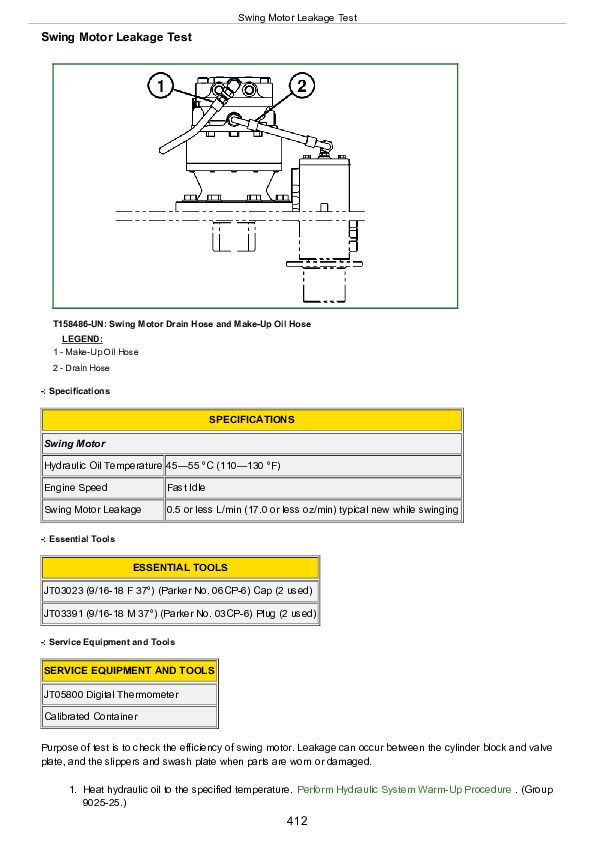
Swing Motor Leakage Test
Propel Motor Leakage Test
Section 9031: Heater
Group 05: Theory of Operation
Heater System
Group 15: Diagnostic Information
Diagnose Heater System Malfunction
Heater Component Location Diagram
Group 25: Tests
Heater System Checks
John Deere Compact Excavator 50CZTS Operation and Test Service Manual (TM2056)


