John Deere 30G Excavator Repair Service Manual (TM14235X19)
Catalog:
Model:
Complete Repair Service Technical Manual for John Deere 30G Excavators, with all the workshop information to maintain, repair, and rebuild like professional mechanics.
John Deere 30G Excavator workshop technical manual (repair) includes:
* Numbered table of contents easy to use so that you can find the information you need fast.
* Detailed sub-steps expand on repair procedure information
* Numbered instructions guide you through every repair procedure step by step.
* Notes, cautions and warnings throughout each chapter pinpoint critical information.
* Bold figure number help you quickly match illustrations with instructions.
* Detailed illustrations, drawings and photos guide you through every procedure.
* Enlarged inset helps you identify and examine parts in detail.
TM14235X19 - John Deere 30G Excavator Technical Manual - Repair.pdf
tm14235x63 - John Deere Excavadora 30G.pdf
tm14235x28 - John Deere Excavatrice 30G.pdf
PRODUCT DETAILS:
Total Pages: 587 pages
File Format: PDF (bookmarked, ToC, Searchable, Printable)
Category: Repair
Language: English Spanish French
Published on 2019/12/30
TABLE OF CONTENTS
Section 00: General Information...9
Group 0001: Safety...9
Safety and Operator Convenience Features...14
Recognize Safety Information...16
Follow Safety Instructions...17
Operate Only If Qualified...18
Wear Protective Equipment...19
Avoid Unauthorized Machine Modifications...20
Control Pattern...21
Control Pattern Selector—If Equipped...22
Inspect Machine...23
Stay Clear of Moving Parts...24
Avoid High-Pressure Fluids...25
Avoid High-Pressure Oils...26
Work In Ventilated Area...27
Avoid Static Electricity Risk When Refueling...28
High Debris Applications...30
Prevent Fires...31
In Case of Machine Fire...32
Prevent Battery Explosions...33
Handle Chemical Products Safely...34
Handle Starting Fluid Safely...35
Decommissioning — Proper Recycling and Disposal of Fluids and Components...36
Prepare for Emergencies...37
Clean Debris from Machine...38
Add Cab Guarding for Special Uses...39
Use Steps and Handholds Correctly...40
Start Only From Operator's Seat...41
Use and Maintain Seat Belt...42
Prevent Unintended Machine Movement...43
Avoid Work Site Hazards...44
Keep Riders Off Machine...46
Avoid Backover Accidents...47
Avoid Machine Tip Over and Machine Damage...48
Use Special Care When Lifting Objects...50
Use Care When Swinging Machine...51
Operate Boom With Care...52
Avoid Power Lines...53
Inspect and Maintain ROPS...54
Travel Safely...55
Prevent Acid Burns...56
Add and Operate Attachments Safely...58
Park and Prepare for Service Safely...59
Service Machines Safely...60
Service Cooling System Safely...61
Remove Paint Before Welding or Heating...62
Make Welding Repairs Safely...63
Drive Metal Pins Safely...64
Use Proper Lifting Equipment...65
Safety Signs...66
Group 0003: Torque Values...10
Metric Bolt and Cap Screw Torque Values...76
Additional Metric Cap Screw Torque Values...78
Unified Inch Bolt and Cap Screw Torque Values...80
Service Recommendations for 37° Flare and 30° Cone Seat Connectors...82
Service Recommendations for O-Ring Boss Fittings...84
Service Recommendations for Flared Connections—Straight or Tapered Threads...86
Service Recommendations for Flat Face O-Ring Seal Fittings...88
O-Ring Boss Fittings in Aluminum Housing Service Recommendations—Excavators...90
O-Ring Face Seal Fittings With SAE Inch Hex Nut and Stud End for High-Pressure Service Recommendations...93
O-Ring Face Seal Fittings With Metric Hex Nut and Stud End for Standard Pressure Service Recommendations...95
O-Ring Face Seal Fittings With Metric Hex Nut and Stud End for High-Pressure Service Recommendations...98
Service Recommendations for Metric Series Four Bolt Flange Fitting...101
Service Recommendations For Inch Series Four Bolt Flange Fittings...103
Inch Series Four Bolt Flange Fitting for High-Pressure Service Recommendations...105
Service Recommendations For Non-Restricted Banjo (Adjustable) Fittings...107
Service Recommendations For O-Ring Boss Fittings With Shoulder...110
Metric 24° O-Ring Seal DIN 20078 Service Recommendations...113
Section 01: Tracks...117
Group 0130: Track System...117
Track Roller Remove and Install...120
Track Carrier Roller Remove and Install...122
Inspect Metal Face Seals...126
Rubber Track Remove and Install...129
Sprocket Remove and Install...134
Front Idler Remove and Install...136
Front Idler Disassemble and Assemble...138
Track Adjuster and Recoil Spring Remove and Install...143
Track Adjuster and Recoil Spring Disassemble and Assemble...144
Section 02: Axles and Suspension Systems (Travel)...152
Group 0250: Axle Shaft, Bearings, and Reduction Gears...152
Travel Gear Case Remove and Install...157
Travel Gear Case Disassemble and Assemble...161
Group 0260: Hydraulic System...152
Travel Motor and Park Brake Remove and Install...172
Travel Motor and Park Brake Disassemble and Assemble...173
Park Brake Valve Disassemble and Assemble...184
Travel Motor and Park Brake Start-Up Procedure...187
Section 04: Engine...189
Group 0400: Removal and Installation...189
Engine Remove and Install...201
Section 05: Engine Auxiliary System...212
Group 0510: Cooling Systems...212
Radiator Remove and Install...217
Hydraulic Oil Cooler Remove and Install...221
Fan, Fan Guard, and Fan Shroud Remove and Install...228
Coolant Recovery Tank Remove and Install...230
Group 0560: External Fuel Supply Systems...212
Fuel Tank Remove and Install...236
Fuel Pump Remove and Install...240
Section 07: Damper Drive (Flex Coupling)...241
Group 0752: Elements...241
Damper Drive (Flex Coupling) Remove and Install...244
Section 17: Frame or Supporting Structure...246
Group 1740: Frame Installation...246
Welding on Machine...249
Group 1749: Chassis Weights...246
Counterweight Remove and Install...255
Section 18: Operator's Station...259
Group 1800: Removal and Installation...259
Cab Remove and Install...263
Canopy Remove and Install...266
Platform Remove and Install...270
Group 1810: Operator Enclosure...259
Windshield Remove and Install...281
Windshield Disassemble and Assemble...283
Windowpanes Remove and Install...288
Windowpanes Dimensions...290
Group 1821: Seat and Seat Belt...259
Seat Remove and Install...298
Seat Belt Remove and Install...299
Group 1830: Heating and Air Conditioning...259
R134a Refrigerant Cautions and Proper Handling...302
Flush and Purge Air Conditioning System...303
R134a Refrigerant Oil Information...306
R134a Refrigerant Recovery, Recycling, and Charging Station Installation Procedure...308
Recover R134a Refrigerant...310
Evacuate R134a System...311
Charge R134a System...313
Air Conditioner Compressor Remove and Install...315
Condenser Remove and Install...317
Heater and Air Conditioner Remove and Install...319
Receiver-Dryer Remove and Install...323
Section 32: Blade (Backfill)...325
Group 3201: Blades...325
Blade Remove and Install...329
Blade Disassemble and Assemble...332
Group 3260: Hydraulic System...325
Blade Cylinder Remove and Install...336
Blade Cylinder Disassemble and Assemble...339
Blade Pilot Valve Remove and Install...343
Blade Pilot Valve Disassemble and Assemble...347
Section 33: Excavator...350
Group 3302: Buckets...350
Bucket Remove and Install...353
Bucket Pin-Up Data...354
Group 3340: Frames...350
Bucket Links Remove and Install...358
Bucket Quick Coupler Remove and Install...360
Arm Remove and Install...363
Boom Remove and Install...367
Boom Swing Post Remove and Install...372
Inspect Pins and Bushings—Front Attachment and Blade...376
Cylinder Specifications...381
Bushing and Seal Remove and Install...382
Group 3360: Hydraulic System...350
Apply Vacuum to Hydraulic Oil Tank...386
General Hydraulic Oil Cleanup Procedure...387
Hydraulic Component Failure Cleanup Procedure...390
Hydraulic Pump 1, 2, and 3 Remove and Install...393
Hydraulic Pump 1, 2, and 3 Disassemble and Assemble...396
Pilot Pump Remove and Install...413
Pilot Pump Disassemble and Assemble...415
Hydraulic Pump Start-Up Procedure...417
Pilot Pressure Regulator and Solenoid Valve Manifold Remove and Install—Pilot Shutoff and Travel Speed Solenoids...418
Pilot Pressure Regulator and Solenoid Valve Manifold Disassemble and Assemble—Pilot Shutoff and Travel Speed Valves...420
Air Conditioner Torque Control Solenoid Valve Remove and Install...424
Air Conditioner Torque Control Solenoid Valve Disassemble and Assemble...426
Pilot Valve (Left and Right) Remove and Install...428
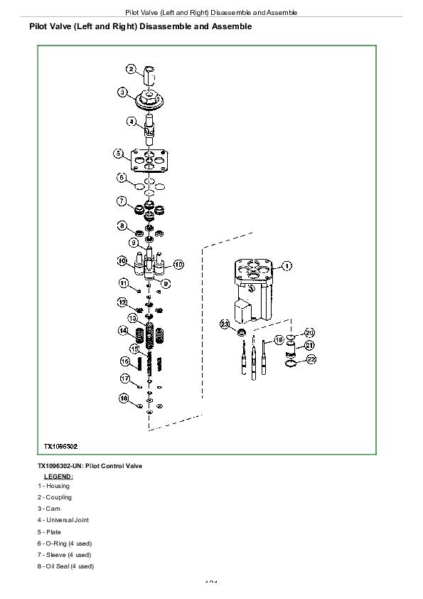
Pilot Valve (Left and Right) Disassemble and Assemble...431
Travel Pilot Valve Remove and Install...440
Travel Pilot Valve Disassemble and Assemble...442
Boom Swing Pilot Valve Remove and Install...447
Boom Swing Pilot Valve Disassemble and Assemble...449
Control Valve Remove and Install...452
Control Valve Disassemble and Assemble...455
Control Lever Pattern Selector Remove and Install...486
Control Lever Pattern Selector Disassemble and Assemble...490
Hydraulic Oil Tank Remove and Install...492
Hydraulic Oil Tank Disassemble and Assemble...497
Hydraulic Oil Cooler Bypass Valve Remove and Install...501
Boom Cylinder Remove and Install...504
Boom Cylinder Disassemble and Assemble...508
Arm Cylinder Remove and Install...512
Arm Cylinder Disassemble and Assemble...516
Bucket Cylinder Remove and Install...520
Bucket Cylinder Disassemble and Assemble...524
Boom Swing Cylinder Remove and Install...528
Boom Swing Cylinder Disassemble and Assemble...532
Hydraulic Cylinder Bleed Procedure...536
Section 43: Swing or Pivoting System...537
Group 4350: Mechanical Drive Elements...537
Swing Gear Case Remove and Install...541
Swing Gear Case Disassemble and Assemble...544
Upperstructure Remove and Install...550
Swing Bearing Remove and Install...554
Group 4360: Hydraulic System...537
Center Joint Remove and Install...563
Center Joint Disassemble and Assemble...568
Center Joint Air Test...572
Swing Motor and Park Brake Remove and Install...573
Swing Motor and Park Brake Disassemble and Assemble...576
Swing Motor and Park Brake Start-Up Procedure...583
Crossover Relief Valve and Make-Up Check Valve Remove and Install...585
John Deere 30G Excavator Repair Service Manual (TM14235X19)


