Yanmar 4TNV98 and 4TNV98T Diesel Engines for John Deere Machines Component Technical Manual (CTM130319)
Catalog:
Model:
Complete service repair manual with Electrical Wiring Diagrams for Yanmar 4TNV98 and 4TNV98T Diesel Engines, with all the technical information to maintain, diagnose, repair, and rebuild like professional mechanics.
Yanmar 4TNV98 and 4TNV98T Diesel Engines for John Deere Machines workshop service repair manual includes:
* Numbered table of contents easy to use so that you can find the information you need fast.
* Detailed sub-steps expand on repair procedure information
* Numbered instructions guide you through every repair procedure step by step.
* Troubleshooting and electrical service procedures are combined with detailed wiring diagrams for ease of use.
* Notes, cautions and warnings throughout each chapter pinpoint critical information.
* Bold figure number help you quickly match illustrations with instructions.
* Detailed illustrations, drawings and photos guide you through every procedure.
* Enlarged inset helps you identify and examine parts in detail.
CTM130319 - Yanmar 4TNV98 and 4TNV98T Diesel Engines for John Deere Machines (Worldwide Edition) Component Technical Manual.pdf
ctm130328 - Yanmar Moteurs diesel 4TNV98 et 4TNV98T (Plate-forme Interim Tier 4/Phase IIIB) -: (Édition mondiale).pdf
ctm130359 - Yanmar Дизельные двигатели 4TNV98 и 4TNV98T (платформа Interim Tier 4 / Stage IIIB) -: (Исполнение для всех стран).pdf
ctm130363 - Yanmar Motores diésel 4TNV98 y 4TNV98T (Tier 4 provisional/Fase IIIB) -: (Edición mundial).pdf
PRODUCT DETAILS:
Total Pages: 1,021 pages
File Format: PDF (Internal Links, Bookmarked, Table of Contents, Searchable, Printable, high quality)
Category: CTM
Language: Spanish English French Russian
Published on 2019/09/30
TABLE OF CONTENTS
Section 01: General Information...29
Group 000: Safety...29
Understand Signal Words...32
Avoid Heating Near Pressurized Fluid Lines...33
Avoid High-Pressure Fluids...34
Avoid Hot Exhaust...35
Avoid Static Electricity Risk When Refueling...36
Construct Dealer-Made Tools Safely...38
Decommissioning — Proper Recycling and Disposal of Fluids and Components...39
Follow Safety Instructions...40
Handle Fluids Safely—Avoid Fires...41
Handling Batteries Safely...42
Illuminate Work Area Safely...44
Install All Guards...45
Live With Safety...46
Practice Safe Maintenance...47
Precautions for Welding...49
Prepare for Emergencies...51
Prevent Acid Burns...52
Prevent Battery Explosions...54
Prevent Machine Runaway...55
Protect Against High Pressure Spray...56
Protect Against Noise...57
Recognize Safety Information...58
Remove Paint Before Welding or Heating...59
Replace Safety Signs...60
Service Cooling System Safely...61
Service Machines Safely...62
Stay Clear of Rotating Drivelines...63
Support Machine Properly...64
Use Proper Lifting Equipment...65
Use Proper Tools...66
Wait Before Opening High-Pressure Fuel System...67
Wear Protective Clothing...68
Work in Clean Area...69
Work In Ventilated Area...70
Group 001: Engine Identification Information...30
Engine Serial Number Plate Information...74
Information Relative to Emissions Regulations...77
Emissions Control System Certification Label...78
Group 002: Fuels, Lubricants, and Coolants...30
Diesel Fuel...82
Diesel Fuel Additive Products...84
Handling and Storing Diesel Fuel...85
Lubricity of Diesel Fuel...86
Testing Diesel Fuel...87
Biodiesel Fuel...88
Minimizing the Effect of Cold Weather on Diesel Engines...89
Diesel Engine Oil...90
Engine Oil and Filter Service Intervals...91
Oil Filters...92
Multipurpose Extreme Pressure (EP) Grease...93
Lubricant Storage...94
Mixing of Lubricants...95
Alternative and Synthetic Lubricants...96
Oilscan™ and CoolScan™...97
Diesel Engine Coolant (engine without wet sleeve cylinder liners)...98
Supplemental Coolant Additives...100
Operating in Warm Temperature Climates...101
Testing Diesel Engine Coolant...102
Drain Intervals for Diesel Engine Coolant...103
John Deere COOL-GARD™ II Coolant Extender...104
Additional Information About Diesel Engine Coolants and John Deere COOL-GARD™ II Coolant Extender...105
Section 02: Repair and Adjustments...106
Group 010: Engine Rebuild...106
Check and Service Cooling System...116
Check Air Intake System...118
Check Electrical System...119
Check Exhaust System...121
Clean Engine...122
Disconnect Turbocharger Oil Inlet Line...123
Engine Assembly Sequence...124
Engine Break-In...126
Engine Disassembly Sequence...128
Engine Repair Stand...130
General Tune-Up Recommendations...131
Install Engine Adapter on Repair Stand...132
Install Lift Straps...133
Lifting Procedure...134
Overhaul Guidelines...135
Safety Precautions...136
Group 020: Cylinder Head and Valves Repair and Adjustment...106
Closed Crankcase Ventilation System — Inspection...138
Closed Crankcase Ventilation System — Installation...139
Closed Crankcase Ventilation System — Removal...140
Cylinder Block Top Deck — Cleaning and Inspection...141
Cylinder Head — Cleaning and Inspection...142
Cylinder Head — Flatness Check...143
Cylinder Head — Installation...144
Cylinder Head — Removal...147
Cylinder Head Gasket — Inspection...149
Push Rod — Cleaning and Inspection...150
Push Rod — Installation...151
Push Rod — Removal...152
Rocker Arm Cover — Inspection...153
Rocker Arm Cover — Installation...154
Rocker Arm Cover — Removal...156
Rocker Arm Shaft Assembly — Assemble...158
Rocker Arm Shaft Assembly — Inspection...161
Rocker Arm Shaft Assembly — Installation...163
Rocker Arm Shaft Assembly — Removal...165
Rocker Arm Shaft Assembly — Tear Down...167
Valve — Cleaning and Inspection...168
Valve — Clearance Adjustment...169
Valve — Grinding...176
Valve — Measurement...179
Valve — Recess Measurement...181
Valve Assembly — Installation...183
Valve Assembly — Removal...186
Valve Keepers and Valve Spring Retainer — Inspection...188
Valve Guide — Cleaning and Measurement...189
Valve Guide — Installation...190
Valve Guide — Removal...193
Valve Seat — Cleaning and Inspection...194
Valve Seat — Grinding...195
Valve Spring — Inspection and Measurement...198
Valve Bridge — Inspection and Measurement...200
Group 030: Cylinder Block, Pistons, and Connecting Rods Repair and Adjustment...107
Connecting Rod and Cap — Inspection...203
Connecting Rod Bearing — Inspection and Measurement...205
Connecting Rod Bearing — Inspection and Measurement (Rod and Crankshaft in Engine)...207
Connecting Rod Cap Screw — Torque Procedure...209
Cylinder Block — Cleaning and Inspection...210
Cylinder Block — Honing and Boring...212
Piston — Cleaning...215
Piston — Inspection...216
Piston and Connecting Rod Assembly — Assemble...217
Piston and Connecting Rod Assembly — Installation...221
Piston and Connecting Rod Assembly — Removal...225
Piston and Connecting Rod Assembly — Tear Down...227
Piston Pin and Bore — Inspection...229
Piston Pin and Bushing — Inspection...231
Piston Pin Bushing — Installation...233
Piston Pin Bushing — Removal...234
Piston Protrusion — Measurement...235
Piston Rings — Inspection...236
Piston Rings — Installation...239
Piston Rings — Removal...241
Piston Skirt — Measurement...242
Group 040: Crankshaft, Main Bearings, and Flywheel Repair and Adjustment...108
Crankshaft — End Play Check...245
Crankshaft — Inspection...247
Crankshaft — Installation...249
Crankshaft — Removal...252
Crankshaft Front Oil Seal — Installation...254
Crankshaft Front Oil Seal — Removal...256
Crankshaft Gear — Installation...257
Crankshaft Gear — Removal...259
Crankshaft Main Bearing — Installation...260
Crankshaft Main Bearing — Measurement...263
Crankshaft Main Bearing — Oil Clearance Check...265
Crankshaft Main Bearing — Removal...267
Crankshaft Main Bearing Cap — Installation...268
Crankshaft Main Bearing Cap — Removal...272
Crankshaft Pulley — Installation...274
Crankshaft Pulley — Removal...275
Crankshaft Pulley Adapter — Installation...276
Crankshaft Pulley Adapter — Removal...278
Crankshaft Rear Oil Seal — Installation...279
Crankshaft Rear Oil Seal — Removal...281
Crankshaft Thrust Bearing — Inspection...282
Flywheel — Inspection...283
Flywheel — Installation...284
Flywheel — Removal...286
Flywheel Housing — Installation...288
Flywheel Housing — Removal...291
Flywheel Ring Gear — Installation...292
Flywheel Ring Gear — Removal...293
Group 050: Camshaft and Timing Gear Train Repair and Adjustment...109
Camshaft — Check End Play...295
Camshaft — Inspection...296
Camshaft — Installation...297
Camshaft — Removal...299
Camshaft — Visual Inspection...301
Camshaft Bushing — Installation...302
Camshaft Bushing — Removal...303
Camshaft Bushing and Bore — Measurement...304
Camshaft Follower — Inspection and Measurement...306
Camshaft Follower — Installation...308
Camshaft Follower — Removal...310
Camshaft Gear — Inspection...311
Camshaft Gear — Installation...312
Camshaft Gear — Removal...313
Camshaft Journal — Measurement...314
Camshaft Lobe — Height Measurement...316
Camshaft Thrust Plate — Measurement...317
Fuel Injection Pump Gear Cover — Installation...318
Fuel Injection Pump Gear Cover — Removal...320
Idler Gear — Inspection...321
Idler Gear — Installation...322
Idler Gear — Removal...325
Timing Gear Cover — Installation...326
Timing Gear Cover — Removal...328
Timing Gear Housing — Installation...329
Timing Gear Housing — Removal...332
Timing Gears — Check Backlash...334
Group 060: Lubrication System Repair and Adjustment...110
Dipstick Tube and Dipstick — Installation...338
Dipstick Tube and Dipstick — Removal...339
Oil Cooler — Installation...340
Oil Cooler — Removal...342
Oil Filter — Installation...344
Oil Filter — Removal...345
Oil Pan — Installation...346
Oil Pan — Removal...348
Oil Pick-Up Tube — Installation...349
Oil Pick-Up Tube — Removal...350
Oil Pump — Assemble...351
Oil Pump — Cleaning and Inspection...352
Oil Pump — Installation...355
Oil Pump — Removal...357
Oil Pump — Tear Down...358
Group 070: Cooling System Repair and Adjustment...110
Coolant Pump Assembly — Inspection...360
Coolant Pump Assembly — Installation...361
Coolant Pump Assembly — Removal...363
Coolant Pump Assembly (EGR Cooler Equipped) — Inspection...365
Coolant Pump Assembly (EGR Cooler Equipped) — Installation...367
Coolant Pump Assembly (EGR Cooler Equipped) — Removal...368
Thermostat — Installation...369
Thermostat — Removal...370
Thermostat Housing (EGR Cooler Equipped) — Installation...371
Thermostat Housing (EGR Cooler Equipped) — Removal...373
Group 080: Air Intake and Exhaust System Repair and Adjustment...110
Air Inlet Elbow — Installation...376
Air Inlet Elbow — Removal...378
EGR Cooler — Installation...380
EGR Cooler — Removal...382
EGR Cooler Coolant Return Tube — Installation...384
EGR Cooler Coolant Return Tube — Removal...386
EGR Cooler Coolant Supply Hose — Installation...387
EGR Cooler Coolant Supply Hose — Removal...388
EGR Cooler Gas Inlet Pipe — Cleaning...389
EGR Cooler Gas Inlet Pipe — Installation...390
EGR Cooler Gas Inlet Pipe — Removal...392
EGR Cooler Gas Outlet Elbow — Cleaning...393
EGR Cooler Gas Outlet Elbow — Installation...394
EGR Cooler Gas Outlet Elbow — Removal...395
EGR Cooler Gas Outlet Pipe — Cleaning...396
EGR Cooler Gas Outlet Pipe — Installation...397
EGR Cooler Gas Outlet Pipe — Removal...399
EGR Gas Outlet Pipe — Cleaning...400
EGR Gas Outlet Pipe — Installation...401
EGR Gas Outlet Pipe — Removal...403
EGR Valve — Cleaning...404
EGR Valve — Inspection...405
EGR Valve — Installation...406
EGR Valve — Removal...408
EGR Valve Coolant Return Line — Installation...410
EGR Valve Coolant Return Line — Removal...411
EGR Valve Coolant Supply Line — Installation...412
EGR Valve Coolant Supply Line — Removal...413
EGR Valve Gas Inlet Pipe — Cleaning...414
EGR Valve Gas Inlet Pipe — Installation...415
EGR Valve Gas Inlet Pipe — Removal...416
Exhaust Manifold — Installation...417
Exhaust Manifold — Removal...419
Exhaust Manifold — Installation (EGR Cooler Equipped)...420
Exhaust Manifold — Removal (EGR Cooler Equipped)...422
Intake Manifold — Installation...424
Intake Manifold — Removal...426
Reed Valve — Cleaning...427
Reed Valve — Inspection...428
Reed Valve — Installation...429
Reed Valve — Removal...431
Turbocharger — Break-In...433
Turbocharger — Failure Analysis...434
Turbocharger — Inspection...437
Turbocharger — Recommendations for Use...445
Wastegate Turbocharger Assembly — Installation...446
Wastegate Turbocharger Assembly — Removal...449
Wastegate Turbocharger Oil Drain Line — Installation...451
Wastegate Turbocharger Oil Drain Line — Removal...453
Wastegate Turbocharger Oil Supply Line — Installation...454
Wastegate Turbocharger Oil Supply Line — Removal...455
Group 090: Fuel System Repair and Adjustment...112
Fuel Injectors — Installation...458
Fuel Injectors — Removal...460
Fuel Injectors — Teardown and Inspection...462
Fuel Injectors — Assembly...465
Fuel Injection Lines and Injection Line Seals — Installation...467
Fuel Injection Lines and Injection Line Seals — Removal...468
Fuel Injection Pump — Installation...470
Fuel Injection Pump — Removal...478
Low-Pressure Fuel Pump — Installation...486
Low-Pressure Fuel Pump — Removal...487
Primary Fuel Filter Assembly — Installation...488
Primary Fuel Filter Assembly — Removal...489
Primary Fuel Filter Element — Installation...490
Primary Fuel Filter Element— Removal...491
Secondary Fuel Filter Assembly — Installation...492
Secondary Fuel Filter Assembly — Removal...493
Secondary Fuel Filter Element — Installation...494
Secondary Fuel Filter Element — Removal...495
Group 100: Starting System Repair and Adjustment...113
Starter Motor — Assemble...500
Starter Motor — Installation...504
Starter Motor — No-Load Test...505
Starter Motor — Removal...507
Starter Motor — Tear Down...508
Starter Motor Armature — Cleaning and Inspection...512
Starter Motor Field Coil — Cleaning and Inspection...515
Starter Motor Magnetic Switch — Cleaning and Inspection...517
Starter Motor Pinion Clutch Assembly — Cleaning and Inspection...520
Group 110: Electrical Engine Control Repair and Adjustment...113
Engine Coolant Temperature Sensor — Installation...523
Engine Coolant Temperature Sensor — Removal...524
Engine Oil Pressure Switch — Installation...525
Engine Oil Pressure Switch — Removal...526
Wiring Harness — Installation...527
Wiring Harness — Removal...528
Section 03: Theory of Operation...529
Group 120: Base Engine Operation...529
General Engine Operation...533
Head Gasket Joint Construction and Operation...535
Group 123: Cooling System...529
Cooling System Component Location Diagram...537
Cooling System Operation...538
Group 126: Lubrication System...529
Lubrication System Component Location Diagram...541
Lubrication System Operation...543
Group 130: Electronic Fuel System...529
Electronic Fuel System Component Location Diagram 1...546
Electronic Fuel System Component Location Diagram 2...548
Electric Low-Pressure Fuel Pump Operation...550
Electric Low-Pressure Fuel System Operation...554
Fuel Injector Operation...552
Fuel Injection Pump Rack Actuator Operation...553
Fuel System Operation...554
Primary Fuel Filter Operation...556
Secondary Fuel Filter Operation...557
Group 135: Air Intake and Exhaust System...529
Air Intake and Exhaust Component Location Diagram 1...559
Air Intake and Exhaust Component Location Diagram 2...560
Air Intake and Exhaust Component Location Diagram 3...561
Air Intake and Exhaust Component Location Diagram 4...562
Air Intake and Exhaust System Operation...563
Cold Start Device Operation...565
EGR Cooler Operation...566
EGR Valve Operation...567
Group 140: Electronic Control System...529
B5115 — Engine Oil Pressure Switch...569
B5208 — Engine Coolant Temperature Sensor...570
B5304 — Engine Speed Sensor...572
B5600 — Water-In-Fuel Sensor...574
Controller Area Network (CAN)...575
Determining Engine Speed...576
Electrical Component Location Diagram 1...577
Electrical Component Location Diagram 2...578
Electrical Component Location Diagram 3...579
Engine Control Module (ECM) System Operation...580
K5811 — Sub Relay...582
K5812 — Main Relay...583
Measuring Pressure...584
Measuring Speed...585
Measuring Temperature...586
M5000 — Starter...587
R5600 — Resistor (120 Ohm)...588
R5601 — CAN Termination Resistor...589
R5606 — Resistor...590
Sensor Supply #1...591
Y5026 — Cold Start Device (CSD)...592
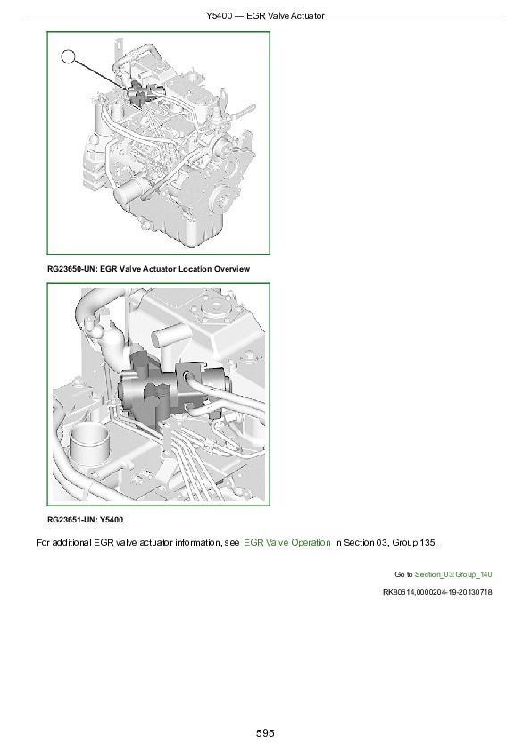
Y5400 — EGR Valve Actuator...594
Y5403 — Fuel Injection Pump Rack Actuator...596
Section 04: Diagnostics...598
Group 150: Observable Diagnostics and Tests...598
Abnormal Engine Noise...598
Coolant in Oil or Oil in Coolant...598
Crankshaft and Main Bearing Failure Analysis...598
ECU Does Not Communicate with Service ADVISOR...598
ECU Does Not Program with Service ADVISOR...598
Engine Coolant Temperature Below Normal...598
Engine Cranks and Will Not Start...598
Engine Does Not Develop Full Power...598
Engine Emits Excessive Black or Gray Exhaust Smoke...598
Engine Emits Excessive Blue Exhaust Smoke...598
Engine Emits Excessive White Exhaust Smoke...598
Engine Misfires or Runs Irregularly...598
Engine Will Not Crank...598
Excessive Fuel Consumption...598
Excessive Oil Carryover...646
Excessive Oil Consumption...648
Fuel in Oil...598
Throttle Not Responding...598
Group 155: Checks, Tests, and Procedures...598
Air in Fuel Check...598
Carbon Cleaning Procedure...658
Charge Air Cooler Test...659
Cooling System Test...660
Crankcase Pressure (Blow-By) Test...598
EGR Cooler Test...667
Engine Cranking Speed Check...668
Engine Oil Pressure Check...670
Fuel Injector Test...672
Fuel Return Lines (Leak off) Restriction Check...674
Fuel Supply Quality Check...675
Fuel System Bleeding...598
Fuel System Check...599
Low-Pressure Fuel System Check...599
Mechanical Compression Test...692
Problem Not Found Procedure...693
Short to Voltage Procedure...599
Terminal Test...697
Thermostat — Testing...701
Turbocharger Oil Seal Leak Check (If Equipped)...703
Verification Procedure...704
Wiggle Test...706
Group 160: Diagnostic Instructions and Information...599
Connecting to Service ADVISOR...709
Diagnostic Trouble Code Designations...711
Digital Multimeter — Using...715
Electrical Circuit Concepts...717
Electrical Noise — Possible Causes...723
Interactive Tests and Calibration Results — Printing, Exporting, or Saving Instructions...724
Internal Data Monitor — Instructions...725
Keep Electronic Control Unit Connectors Clean...731
Servicing Electronic Control Units...732
Welding Near Electronic Control Units...733
Yanmar Display Calibration Values Test...734
Yanmar Engine Control Module Replacement Calibration...735
Yanmar Fuel Pump Replacement Calibration...738
Group 161: DTC SPN — 000001 - 000199...599
000029.00 - Secondary Throttle Signal Extremely High...599
000029.01 - Secondary Throttle Signal Extremely Low...599
000029.02 - Secondary Throttle Signal Invalid...599
000029.03 - Secondary Throttle Signal Out of Range High...599
000029.04 - Secondary Throttle Signal Out of Range Low...599
000029.08 - Secondary Throttle Signal Abnormal...599
000029.15 - Secondary Throttle Signal Slightly High...599
000091.00 - Primary Throttle Signal Extremely High...599
000091.01 - Primary Throttle Signal Extremely Low...600
000091.02 - Primary Throttle Signal Invalid...600
000091.03 - Primary Throttle Signal Out of Range High...600
000091.04 - Primary Throttle Signal Out of Range Low...600
000091.15 - Primary Throttle Signal Slightly High...600
000100.01 - Engine Oil Pressure Signal Extremely Low...600
000100.04 - Engine Oil Pressure Signal Out of Range Low...600
000108.02 - Barometric Pressure Signal Invalid...600
000108.03 - Barometric Pressure Signal Out of Range High...600
000108.04 - Barometric Pressure Signal Out of Range Low...600
000110.00 - Engine Coolant Temperature Signal Extremely High...600
000110.02 - Engine Coolant Temperature Signal Invalid...600
000110.03 - Engine Coolant Temperature Signal Out of Range High...600
000110.04 - Engine Coolant Temperature Signal Out of Range Low...600
000158.00 - Switched Battery Voltage Extremely High...600
000158.01 - Switched Battery Voltage Extremely Low...600
000167.01 - Charging System Voltage Extremely Low...600
000167.04 - Charging System Circuit Out of Range Low...600
000190.00 - Engine Speed Extremely High...600
Group 162: DTC SPN - 000200 — 000699...600
000628.02 - ECM Internal Fault 1...600
000628.12 - ECM Internal Fault 2...600
000630.02 - ECM Internal Fault 3...600
000630.12 - ECM Internal Fault 4...600
000638.02 - Fuel Injection Pump Rack Actuator Invalid...600
000638.03 - Fuel Injection Pump Rack Actuator Circuit Out of Range High...600
000638.04 - Fuel Injection Pump Rack Actuator Circuit Out of Range Low...600
000638.07 - Fuel Injection Pump Rack Actuator Not Responding...600
000639.12 - CAN Communication Error...600
Group 163: DTC SPN - 000700 — 001999...600
001078.04 - Engine Speed Sensor Signal Out of Range Low...600
001079.02 - Sensor Supply #1 Voltage Invalid...600
001079.03 - Sensor Supply #1 Voltage Out of Range High...600
001079.04 - Sensor Supply #1 Voltage Out of Range Low...601
001136.00 - Engine Control Module (ECM) Internal Temperature Extremely High...601
001136.02 - Engine Control Module (ECM) Internal Temperature Sensor Intermittent Error...601
001136.03 - Engine Control Module (ECM) Internal Temperature Signal Out of Range High...601
001136.04 - Engine Control Module (ECM) Internal Temperature Signal Out of Range Low...601
001202.02 - Vehicle Immobilizer System Invalid...601
001210.03 - Fuel Injection Pump Rack Position Sensor Signal Out of Range High...601
001210.04 - Fuel Injection Pump Rack Position Sensor Signal Out of Range Low...601
001485.04 - Engine Control Module (ECM) Main Relay Out of Range Low...601
Group 167: DTC SPN - 004000 — 529999...601
522241.02 - Fuel Injection Pump Rack Actuator Relay Invalid...601
522241.03 - Fuel Injection Pump Rack Actuator Relay Out of Range High...601
522241.04 - Fuel Injection Pump Rack Actuator Relay Out of Range Low...601
522242.02 - Cold Start Relay Driver Circuit Invalid...601
522242.03 - Cold Start Aid Relay Driver Circuit Out of Range High...601
522242.04 - Cold Start Aid Relay Driver Circuit Out of Range Low...601
522243.02 - Air Heater Relay Driver Circuit Invalid...601
522243.03 - Air Heater Relay Driver Circuit Out of Range High...601
522243.04 - Air Heater Relay Driver Circuit Out of Range Low...601
522251.03 - EGR Valve Actuator Drive 1 Circuit Out of Range High...601
522251.04 - EGR Valve Actuator Drive 1 Circuit Out of Range Low...601
522252.03 - EGR Valve Actuator Drive 2 Circuit Out of Range High...601
522252.04 - EGR Valve Actuator Drive 2 Circuit Out of Range Low...601
522253.03 - EGR Valve Actuator Drive 3 Circuit Out of Range High...601
522253.04 - EGR Valve Actuator Drive 3 Circuit Out of Range Low...601
522254.03 - EGR Valve Actuator Drive 4 Circuit Out of Range High...601
522254.04 - EGR Valve Actuator Drive 4 Circuit Out of Range Low...601
522314.00 - Engine Coolant Temperature Extremely High...601
522323.00 - Air Filter Pressure Differential Extremely High...601
522329.00 - Water-In-Fuel Level Extremely High...601
522402.04 - Auxiliary Speed Sensor Out of Range Low...601
522727.12 - ECM Internal Fault 5...601
522728.12 - ECM Internal Fault 6...601
522730.08 - Vehicle Immobilizer System CAN Communication Error...602
522730.12 - Vehicle Immobilizer System Pulse Communication Error...602
Section 05: Tools and Other Materials...999
Group 170: Special Tools...934
23622...937
313793...938
D01045AA...939
D01109AA...940
D01110AA...941
D01168AA...942
D05012ST-A...943
D05223ST...944
D15001NU...945
D17024BR...946
D17511CI...947
D17525CI...948
D17526CI...949
D17527CI...950
J-35616-20...951
JDE135...952
JDE138...953
JDF13B...954
JDG451...955
JDG1322...956
JDG1676...957
JDG10233...958
JDG10243...959
JDG10407...960
JDG10408...961
JDG10446...962
JDG10447...963
JDG10450...964
JDG10451...965
JDG10456...966
JDG10457...967
JDG10460...968
JDG10461...969
JDG10466...970
JDG10273...971
JDG10788...972
JDG10789...973
JDG10790...974
JDG10874...975
JDG11233...976
JDG11348...977
JDG11349...978
JDG11461...979
JDG11462...980
JDG11464...981
JDG11465A...982
JDG11508...983
JDG11548...984
JDG11549...985
JDG11574...986
JDG11575...987
JDG11602...988
JT01674A...989
JT05470...990
JT05697A...993
JT07253...994
JT07306...995
JT25510...996
Group 180: Lubricants, Sealants, and Cleaners...935
Other Materials...999
Section 06: Specifications...1001
Group 190: Repair and Diagnostic Specifications...1001
Metric Bolt and Screw Torque Values...1004
Unified Inch Bolt and Screw Torque Values...1006
Engine Schematic...1008
Wiring Diagram...1010
Yanmar 4TNV98 and 4TNV98T Diesel Engines for John Deere Machines Component Technical Manual (CTM130319)


