John Deere Tractor 5303 Diagnostic and Repair Service Manual (TM4827)
Catalog:
Model:
Complete All Inclusive Technical Manual with electrical wiring diagrams for John Deere Tractor 5303, with workhop information to maintain, diagnose, repair, and rebuild like professional mechanics (Diagnosis, Operation, Tests, Repair, Service, Troubleshooting).
John Deere Tractor 5303 workshop technical service repair manual includes:
* Numbered table of contents easy to use so that you can find the information you need fast.
* Detailed sub-steps expand on repair procedure information
* Numbered instructions guide you through every repair procedure step by step.
* Troubleshooting and electrical service procedures are combined with detailed wiring diagrams for ease of use.
* Notes, cautions and warnings throughout each chapter pinpoint critical information.
* Bold figure number help you quickly match illustrations with instructions.
* Detailed illustrations, drawings and photos guide you through every procedure.
* Enlarged inset helps you identify and examine parts in detail.
TM4827 English- John Deere Tractor 5303 Diagnostic and Repair Technical Manual.pdf
TM801054 Portuguese - Tratores 5303 e 5403 — Manual Técnico de Reparos.pdf
Published on 2006/12/01
Total Pages: 1,261 pages
File Format: PDF/EPUB/MOBI/AZW (PC/Mac/Android/Kindle/iPhone/iPad; bookmarked, ToC, Searchable, Printable)
Language: English Portuguese
MAIN SECTIONS
Foreword
General Information
Safety
General Specifications
Fuel and Lubricants
Serial Number Locations
Features and Accessories
Engine Repair
Engine
Cylinder Head and valves
Cyl. Block, Liners, Pistons & Rods
Crankshaft, Main Bearings and Flywheel
Camshaft and Timing Gear Train
Lubrication System
Cooling System
Fuel and Air Repair
Fuel System
Air Intake and Exhuast System
Speed Control Linkage
Electrical Repair
Battery, Starter and Alternator
Electrical System Components
Wiring Harness
Power Train Repair
Clutch Housing
Clutch Assembly-CollarShift Transmissions
CollarShift Transmission
Rear PTO Drive Shaft
Differential
Final Drives
Steering and Brake Repair
Steering Repair
Brake Repair
Hydraulic Repair
Hydraulic Pump and Filter
MITA Rockshaft
JD Rockshaft
Selective Control Valve (SCV)
Miscellaneous Repair
Front Axle
Wheels
3-Point Hitch
Operator Station Repair
Seat and Support
ROPS
Operator Platform
Fenders
Operational Checkout Procedures
Operational Checkout Procedures
Engine Operation, Tests and Adjustments
Component Location
Theory of Operation
Diagnosis, Tests and Adjustments
Fuel/Air Operation, Test and Adjustments
Component Location
Theory of Operation
Diagnosis, Tests and Adjustments
Electrical System Operation, Tests & Adjust
Component Location
Theory of Operation
Diagnosis, Test and Adjust
Wiring Schematics
Power Train Operation, Tests and Adjustments
Component Location-CollarShift Transmission
Theory of Operation-CollarShift Transmission
Diagnosis, Tests, and Adjustments-CS Transmission
Steering and Brake Operation, Test & Adjustments
Component Location
Theory of Operation
Diagnosis, Tests and Adjustments
Hydraulic System Operation, Test and Adjustments
Component Location
Theory of Operation
Diagnosis
Hydraulic Tests - Without SCV
Hydraulic Tests-With SCV
Hydraulic Tests - All
Adjustments - MITA Rockshaft
Adjustments - JD Rockshaft
Hydraulic Schematics
TABLE OF CONTENTS
Section 10: General Information................25
Group 05: Safety................25
Recognize Safety Information................28
Understand Signal Words................29
Follow Safety Instructions................30
Handle Fluids Safely-Avoid Fires................31
Prevent Battery Explosions................32
Prepare for Emergencies................33
Prevent Acid Burns................34
Service Cooling System Safely................36
Avoid High-Pressure Fluids................37
Park Machine Safely................38
Support Machine Properly................39
Wear Protective Clothing................40
Work in Clean Area................41
Service Machines Safely................42
Work In Ventilated Area................43
Illuminate Work Area Safely................44
Replace Safety Signs................45
Use Proper Lifting Equipment................46
Service Tires Safely................47
Avoid Harmful Asbestos Dust................48
Avoid Heating Near Pressurized Fluid Lines................49
Remove Paint Before Welding or Heating................50
Use Proper Tools................51
Dispose of Waste Properly................52
Live With Safety................53
Group 10: General Specifications................840
Machine Specifications................840
Repair Specifications................840
Ground Speed Estimates................62
Service Recommendations for O-Ring Boss Fittings................64
Service Recommendations for Flat Face O-Ring Seal Fittings................66
Metric Bolt and cap screw Torque Values................68
Unified Inch Bolt and cap screw Torque Values................70
Group 20: Fuel and Lubricants................26
Diesel Fuel................74
Minimizing the Effect of Cold Weather on Diesel Engines................76
Fuel Storage................78
Do Not Use Galvanized Containers................79
Fill Fuel Tank................80
Diesel Engine Oil................81
Diesel Engine Coolant................83
Transmission and Hydraulic Oil................85
Grease (Specific Application)................86
Grease................87
Alternative and Synthetic Lubricants................88
Lubricant Storage................89
Group 25: Serial Number Locations................26
Serial Numbers................91
Product Identification Number Location................92
Engine Serial Number Location................93
Fuel Injection Pump Serial Number Location................94
Alternator Serial Number Location................95
Power Steering Valve Serial Number Location................96
Starter Serial Number Location................97
Transmission Serial Number Location................98
Front Axle Serial Number Location................99
Group 30: Features and Accessories................101
Features and Accessories................101
Standard Features................102
Field Installed Optional Kits and Accessories................104
Section 20: Engine Repair................105
Group 05: Engine................105
Service Equipment and Tools................604
Specifications................840
John Deere Engine Repair-Use CTM8................114
Remove Engine................115
Install Engine................121
Engine Disassembly Sequence................127
Sealant Application Guidelines................129
Engine Re-Assembly Sequence................130
Engine break-in guidelines................132
Perform engine break-in................133
Diesel Engine Break-In Oil................134
Group 10: Cylinder Head and valves................105
Special or Essential Tools................841
Specifications................840
Torques for Hardware................341
Cylinder Head - Exploded View................196
Check Valve Lift................147
Remove cylinder head................148
Clean Injection Nozzle Bores................150
Valve Actuating Parts................151
Remove Valves and Valve Springs................152
Checking Cylinder Head Flatness................153
Clean Valve Guides................154
Measure Valve Guides................155
Knurl Valve Guides................157
Clean and Inspect Valve Seats................158
Lapping Valve Seats................159
Check Valve Recess................160
Remove Valve Seat Inserts................161
Valve Seat Insert Installation................164
Check Valves................165
Grind Valves................166
Check Valve Spring Compression................167
Inspect Valve Rotators................168
Install Valves................169
Install Cylinder Head................171
Torque Turn Tightening Method................173
Disassembling and Checking Rocker Arm Shaft................175
Reassembling Rocker Arm Shaft................177
Install Rocker Arm Assembly................178
Valve Clearance................179
Valve Adjustment Sequence................180
Install Rocker Arm Cover................181
Final Work................183
Group 15: Cyl. Block, Liners, Pistons & Rods................106
Special or Essential Tools................841
Specifications................840
Torques for Hardware................341
Exploded View................196
Connecting Rods - General Information................197
Remove Pistons and Connecting Rods................199
Measure Cylinder Liner Bore................201
Remove Cylinder Liners................202
Cylinder Liner Deglazing................203
Cylinder Block Cleaning................204
Check Piston Cooling Jets................205
Cam Follower Bore Measure................206
Measure Camshaft Bore................207
Remove Camshaft Bushing................208
Install Camshaft Bushing................209
Measure Crankshaft Bore................210
Replace Crankshaft Bearing Caps................211
Cylinder Block Top Desk Flatness................212
Measure Cylinder Liner Protrusion................213
Liner Packing Installation................215
Liner O-Ring Installation................216
Install Cylinder Liners................217
Measure Connecting Rod Bearing................218
Rod Bearing Clearance................220
Measure Connecting Rod Bushing................221
Replace Connecting Rod Bushing (3029D)................222
Measure Piston Pin................223
Clean and Inspect Pistons................224
Measure Piston Pin Bore................225
Piston Top Ring Groove................226
Second and Third Piston Ring Grooves................227
Piston Head and Skirt Checking................228
Install Piston Rings................229
Piston Rings Staggering................231
Piston/Liner Set Information................232
Assemble Piston and Connecting Rod................233
Install Piston and Connecting Rod................235
Measure Piston Protrusion................238
Complete Final Assembly................240
Group 20: Crankshaft, Main Bearings and Flywheel................107
Special or Essential Tools................841
Specifications................840
Torques For Hardware................376
Remove Crankshaft Pulley................249
Install Crankshaft Pulley................250
Flywheel Removal................251
Flywheel Ring Gear Replacement................252
Install Ball Bearing................253
Install Flywheel................254
Remove Crankshaft Rear Oil Seal................255
Flywheel Housing Replacement................258
Install Oil Seal/Wear Sleeve................260
Crankshaft End Play Measure................261
Remove Crankshaft................263
Crankshaft Inspection................264
Check Crankshaft Journal Diameter................265
Determine Crankshaft Main Bearing Clearance Using PLASTIGAGEPLASTIGAGE is a trademark of DANA Corp.................108
Regrind Crankshaft................268
Crankshaft Regrinding Guidelines................269
Micro-Finishing Specifications................840
Replace Crankshaft Gear................271
Install Main Bearing Inserts................273
Install 2-Piece Thrust Bearing................274
Crankshaft Installation................275
Group 25: Camshaft and Timing Gear Train................108
Special or Essential Tools................841
Specifications................840
Torques for Hardware................341
Remove Crankshaft Front Oil Seal................283
Remove Timing Gear Cover................284
Measure Timing Gear Backlash................285
Camshaft End Play Measure................286
Remove Camshaft................287
Measure Camshaft Journal................288
Measure Height of Cam Lobe................289
Replace Camshaft Gear................290
Install Camshaft................291
Check Cam Follower................292
Idler Gear End Play Measure................293
Remove Front Plate................294
Idler Gear Bushing and Shaft Measure................296
Idler Gear Bushing Replacement................297
Remove Idler Shaft................298
Install Idler Shaft Spring Pin................299
Install Idler Shafts................300
Install Front Plate................301
Install Upper Timing Gear Train................303
Install Lower Timing Gear Train................305
Install Oil Deflector................306
Timing Gear Cover Identification................307
Install Timing Gear Cover................308
Install Crankshaft Front Oil Seal................310
Install Wear Ring................311
Install Auxiliary Equipment................312
Group 30: Lubrication System................109
Special or Essential Tools................841
Specifications................840
Torques for Hardware................341
Oil Cooler Identification................317
Remove Oil Cooler................318
Replace Oil Cooler Nipple................319
Install Oil Cooler................320
Replace Oil Cooler/Filter Bracket on Engine with Auxiliary Drive................321
Remove Oil Pressure Regulating Valve................323
Replace Oil Pressure Regulating Valve Seat................324
Install Oil Pressure Regulating Valve................325
Replace Oil Dipstick Guide................326
Replace Oil By-Pass Valve................327
Replace Oil Pump Strainer................328
Remove Oil Pump................329
Oil Pump Gear Axial Clearance................330
Oil Pump Gear Radial Clearance................331
Oil Pump Specifications................840
Oil Pump Installation................333
Install Oil Pan................336
Group 35: Cooling System................109
Special or Essential Tools................841
Specifications................840
Torques for Hardware................341
Remove And Inspect Radiator................342
Water Pump - Exploded View................345
Remove Water Pump................346
Disassemble Water Pump................347
Assemble Water Pump................349
Install Water Pump................352
Inspect Thermostat................353
Cooling System Deaeration................355
Check Fan/Alternator Belt Tension................356
Install Fan................358
Install Radiator................360
Replace Thermostat................362
Section 30: Fuel and Air Repair................365
Group 05: Fuel System................365
Special or Essential Tools................841
Self-Manufactured Tool Template For Front Plate Replacement................374
Specifications................840
Torques For Hardware................376
Injection Pump, Nozzle and Governor Repair-Use CTM8................377
Remove, Inspect and Install Fuel Tank................378
Replace Fuel Filter................381
Remove and Install Fuel Filter/Primer Pump Assembly................382
Group 10: Air Intake and Exhuast System................365
Remove, Inspect, and Install Air Cleaner Elements................385
Check Air inlet Pipe................387
Exhaust Manifold Inspection................388
Group 15: Speed Control Linkage................365
Inspect and Repair Speed Control Linkage................391
Section 40: Electrical Repair................393
Group 05: Battery, Starter and Alternator................393
Starter Repair-Use CTM77................395
Remove and Install Battery................396
Remove and Install Starter................398
Replace Alternator/Regulator................399
Group 10: Electrical System Components................393
Service Equipment and Tools................604
Other Material................689
Replace Air Filter Restriction Sensor................404
Replace Coolant Temperature Sender................405
Replace Engine Speed Sensor................406
Replace Engine Oil Pressure Sensor................407
Replace Key Switch................408
Replace Light Switch................409
Replace Turn Signal Controller................411
Replace Instrument Panel................412
Replace Rear PTO Switch................414
Replace Park position Start Switch................415
Replace Fuel Level Sender................416
Group 15: Wiring Harness................393
Special or Essential Tools................841
Service Parts Kits................629
Remove Connector Body from Blade Terminals................421
Replace WEATHER PACKWEATHER PACK is a trademark of Packard Electric. Connector................393
Install WEATHER PACKWEATHER PACK is a trademark of Packard Electric. Contact................393
Replace Tractor Wiring Harness................426
Section 50: Power Train Repair................429
Group 05: Clutch Housing................429
Service Equipment and Tools................604
Other Material................689
Specifications................840
Separate Engine from Clutch Housing................435
Install Engine to Clutch Housing................440
Replace Clutch Housing Seal................445
Inspect and Repair Clutch Pedal and Linkage................447
Group 10: Clutch Assembly-CollarShift Transmissions................429
Essential Tools................841
Service Equipment and Tools................604
Other Material................689
Specifications................840
Remove and Install Clutch Assembly................454
Disassemble and Inspect Clutch Assembly................457
Assemble Clutch Assembly................465
Traction Clutch Finger Adjustment................471
PTO Clutch Finger Adjustment................473
Remove and Inspect Clutch Release Mechanism and Shafts................475
Install Clutch Release Mechanism and Shafts................479
Group 15: CollarShift Transmission................429
Specifications................840
Separate Clutch Housing from Transmission................484
Install Clutch Housing to Transmission................488
Inspect and Repair Gear and Range Shift Levers................492
Remove Transmission................496
Disassemble and Inspect Transmission................499
Assemble Transmission................507
Install Transmission................513
Disassemble, Inspect and Assemble Gear Shift Shaft Assemblies................520
Disassemble, Inspect, and Assemble Transmission Top Shaft-CollarShift Transmission................522
Disassemble, Inspect, and Assemble Range Reduction Shaft................525
Disassemble, Inspect and Assemble Driven Shaft................527
Remove, Inspect, and Install Range Gears................529
Remove, Inspect, and Install Reverse Idler Shaft................531
Group 20: Rear PTO Drive Shaft................430
Other Material................689
Specifications................840
Remove, Inspect and Install Rear PTO Lever and Linkage................536
Remove and Install Standard Rear PTO Drive Shaft Assembly................538
Disassemble, Inspect and Assemble Standard Rear PTO Drive Shaft Assembly................540
Group 25: Differential................430
Essential Tools................841
Service Equipment and Tools................604
Other Material................689
Specifications................840
Service Parts Kits................629
Remove and Install Differential Assembly................549
Disassemble, Inspect, and Assemble Differential Assembly................551
Remove and Inspect Differential Drive Shaft................553
Install Differential Drive Shaft................557
Remove, Inspect, and Install Differential Lock Assembly................561
Differential Cone Point Adjustment................563
Differential Backlash Adjustment................565
Group 30: Final Drives................430
Service Equipment and Tools................604
Other Material................689
Specifications................840
Remove and Install Final Drive Assembly................571
Remove and Inspect Planetary Drive Assembly................573
Install Planetary Drive Assembly................576
Remove, Inspect, and Install Axle Shaft Assembly................579
Section 60: Steering and Brake Repair................583
Group 05: Steering Repair................583
Other Material................689
Specifications................840
Service Parts Kits................629
Remove and Install Steering Column and valve................588
Disassemble and Inspect Steering valve................590
Assemble Steering valve................594
Remove and Install Steering Cylinder................599
Disassemble, Inspect and Assemble Steering Cylinder................600
Remove, Inspect and Install Tie Rod Assembly................601
Group 10: Brake Repair................583
Service Equipment and Tools................604
Other Material................689
Specifications................840
Remove and Install Brake valve and Pedals................607
Disassemble and Inspect Brake Pedals and valve................609
Brake valve Cross Section................612
Assemble Brake valve................614
Remove and Inspect Brakes................617
Install Brakes................620
Inspect and Replace Brake Hydraulic Lines................623
Section 70: Hydraulic Repair................625
Group 05: Hydraulic Pump and Filter................625
Specifications................840
Service Parts Kits................629
Remove, Inspect, and Install Hydraulic Oil Pick-Up Screen................630
Remove and Install Hydraulic Pump................631
Remove Hydraulic Pump External Components................633
Disassemble and Inspect Hydraulic Pump................634
Assemble Hydraulic Pump................637
Install Hydraulic Pump External Components................639
Remove and Install Hydraulic Oil Filter/Manifold................641
Inspect and Replace Hydraulic Supply and Suction/Return Lines................642
Group 10: MITA Rockshaft................625
Other Material................689
Specifications................840
Remove, Inspect, and Install Rockshaft Control Lever Assembly................647
Remove, Inspect, and Install Rockshaft Control Lever Support Assembly................650
Remove, Inspect and Install Rockshaft Control Linkage................660
Replace Main Relief valve................671
Remove, Inspect and Install Rate-of-Drop valve................673
Replace Rockshaft Control valve................676
Remove and Install Rockshaft Case................713
Remove, Inspect and Install Rockshaft Lift Arms................682
Remove, Inspect and Install Rockshaft Piston and Cylinder................686
Group 10: JD Rockshaft................625
Other Material................689
Specifications................840
Inspect and Rockshaft Control Assembly................691
Inspect and Repair Rockshaft Control Linkage................696
Inspect and Repair Draft Sensing Support Assembly................700
Replace Main Relief Valve................702
Replace Rockshaft Surge Relief Valve................704
Remove, Inspect, and Install Rate-of-Drop Valve................706
Replace Rockshaft Control Valve................709
Remove and Install Rockshaft Case................713
Remove, Inspect, and Install Rockshaft Lift Arms................716
Remove, Inspect, and Install Rockshaft Piston and Cylinder................718
Group 15: Selective Control Valve (SCV)................626
Install Single Selective Control Valve (SCV)................726
Install Rear Coupler Bracket................731
Install Hydraulic Hoses................746
Install Second Selective Control Valve (SCV)................740
Assemble Rear Quick Coupler................744
Install Hydraulic Hoses................746
Section 80: Miscellaneous Repair................751
Group 05: Front Axle................751
Specifications................840
Remove and Install Front Axle-2WD................754
Inspect and Replace Pivot Pin and Bushings-2WD Axle................757
Remove and Install Spindle Assembly-2WD Axle................758
Inspect and Replace Spindle Shaft Bushings-2WD Axle................760
Group 10: Wheels................751
Specifications................840
Inspect and Replace Front Wheel Bearings................763
Tighten Bolts-Rear Axle................765
Group 15: 3-Point Hitch................751
Specifications................840
Inspect and Repair Fixed Draft Links................768
Inspect and Repair Lift Link................769
Inspect and Repair Adjustable Lift Link................771
Inspect and Repair Center Link................773
Remove and Install Wagon Hitch and Support................775
Section 90: Operator Station Repair................776
Group 05: Seat and Support................776
Specifications................840
Remove and Install Seat and Support................779
Group 10: ROPS................776
Specifications................840
Remove and Install ROPS................783
Group 15: Operator Platform................776
Specifications................840
Remove and Install Right-Side Platform................788
Remove and Install Left-Side Platform and Step................790
Group 20: Fenders................776
Remove and Install Fenders................793
Section 210: Operational Checkout Procedures................794
Group 10: Operational Checkout Procedures................794
Operational Checkout Procedure Information................796
Engine Oil Level and Condition Check................797
Coolant Level and Condition Check................798
Transmission and Hydraulic Oil Check................799
Fan and Belt Check................800
Fuel System Check................801
Air Intake System Check................802
Electrical System Check................803
Hydraulic System Check................805
Indicator Lamps Check................807
Engine Start Check................808
Transmission Park position Start Check................809
Engine Fast and Slow Idle Operation................810
Power Steering Check................811
Differential Lock Check................812
Clutch Check................813
Transmission Shift Check................814
Range Lever Shift Check................815
Brake Check................817
Rockshaft Check................818
Selective Control Valve Check................820
Miscellaneous Checks................822
Section 220: Engine Operation, Tests and Adjustments................823
Group 05: Component Location................823
Component Location Information................1179
Engine External Components-Left-Hand Side................827
Engine External Components-Right-Hand Side................829
Group 10: Theory of Operation................823
Theory of Operation Information................1183
Engine Lubrication System................833
Engine Cooling System Operation................837
Group 15: Diagnosis, Tests and Adjustments................823
Specifications................840
Essential Tools................841
Diagnostic Information................1207
Engine Turns Over But Will Not Start or Starts Hard................843
Engine Runs Irregularly or Stalls Frequently................844
Engine Runs Rough................845
Engine Low Power................846
Engine Smokes-Black or Grey................848
Engine Smokes Excessively-White................849
Engine Uses Excess Fuel................850
Engine Has Excess Noise or Vibration................851
Engine Uses Excess Oil or Smokes Blue................852
Engine Has Low Oil Pressure................853
Engine Coolant Operating Temperature Incorrect................854
Oil In Coolant or Coolant in Oil................855
Radiator Bubble Test................856
Cooling System Test................859
Radiator Cap Pressure Test................860
Engine Oil Pressure Test................861
Cylinder Compression Pressure Test................863
Throttle Lever Adjustment................865
Fuel Injection Pump Setting................866
Idle Speed Adjustment................870
Valve Clearance Adjustment................871
Fan/Alternator Drive Belt Adjustment................873
Bleeding Fuel System................875
Bleed Fuel System At Fuel Injection Nozzles................876
Section 230: Fuel/Air Operation, Test and Adjustments................877
Group 05: Component Location................877
Component Location Information................1179
Fuel System Components................880
Air Intake System Components................882
Group 10: Theory of Operation................877
Theory of Operation Information................1183
Fuel System Operation................885
Fuel Filter Pump Operation................887
Fuel Injection Nozzle Operation................889
Fuel Transfer (Feed) Pump Operation................892
In-Line Fuel Injection Pump Operation................894
Governor Operation (In-Line Pump)................896
Air Intake System Operation................898
Group 15: Diagnosis, Tests and Adjustments................877
Diagnostic Information................1207
Fuel/Air Diagnosis, Tests and Adjustments................902
Section 240: Electrical System Operation, Tests Section 240: Electrical System Operation, Tests & Adjust{pgNO}903 Adjust................903
Group 05: Component Location................903
Component Location Information................1179
Engine Electrical Components-Right Hand Side................908
Engine Electrical Components-Left Hand Side................909
Dash And Center Control Console Electrical Components................910
Tractor Electrical Components................912
Group 10: Theory of Operation................903
Theory of Operation Information................1183
Fuse Block and Fuses................916
Relays................917
Starting System Operation-Normal................918
Starting System Operation-Bypass Attempt................921
Charging System Operation................924
Lighting System Operation-Left Turn Signals And Warn Lights................926
Lighting System Operation-Right Turn Signals And Warn Lights................930
Lighting System Operation-Warning Lights................933
Lighting System Operation-Tail Lights................935
Lighting System Operation-Headlights and Instrument Lights................937
Instrument Panel System Operation-Tachometer/Hour Meter................939
Instrument Panel System Operation-Fuel Gauge................941
Instrument Panel System Operation-Temperature Gauge................943
Air Filter Restriction Indicator Operation................945
7-Pin Trailer Outlet Connector Operation................903
Horn Operation................949
Rear Work Light................950
Group 15: Diagnosis, Test and Adjust................903
Diagnostic Information................1207
Wire Color Chart................954
Starting System Test Points-Normal Operation................956
Starting System Test Points-Bypass Attempt................963
Charging System Test Points................968
Lighting System Test Points-Turn Signals And Enhanced Tail Lights................973
Lighting System Test Points-Warning Lights................978
Lighting System Test Points-Rear Flood Light................982
Lighting System Test Points-Headlights and Instrument Lights................985
Instrument Panel System Test Points-Tachometer/Hourmeter................993
Instrument Panel System Test Points-Fuel Gauge................998
Instrument Panel System Test Points-Temperature Gauge................1002
Instrument Panel System Test Points-Oil Pressure Gauge................1007
Air Filter Restriction Test Points................1012
Optional Horn Test Points................1017
Accessory Relay and Trailer Connector Test Points................1020
Battery Voltage and Specific Gravity Tests................1026
Charge Battery................1028
Battery Load Test................1030
Starter AMP Draw/RPM Test................1032
Starter No-Load AMP Draw/RPM Test................1034
Alternator/Regulator Test................1036
Starter Solenoid Test................1038
Starter Relay Test................1039
Key Switch Test................1040
Plug-In Relay Test................1042
Mini Plug-In Relay................1044
Diode Pack Test................1046
Fuse Test................1048
Park position Start Switch Test................1049
PTO Switch Test................1050
PTO Seat Switch Test................1051
Light Switch Test................1052
Turn Signal Controller Test................1054
Fuel Shut-Off Solenoid Test................1055
Group 20: Wiring Schematics................904
Schematic Information................1057
Component Identification Table................1058
Electrical Schematic Legend................1063
Electrical Schematic Legend................1063
Section 250: Power Train Operation, Tests and Adjustments................1066
Group 05: Component Location-CollarShift Transmission................1066
Component Location Information................1179
Power Train Components-(CollarShift )................1070
Clutch Components-dual................1071
Transmission Components-CollarShift................1073
Final Drive Components................1075
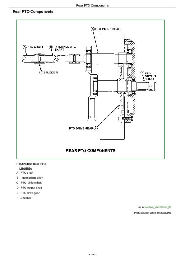
Rear PTO Components................1076
Group 10: Theory of Operation-CollarShift Transmission................1066
Theory of Operation Information................1183
Clutch Operation-Dual Clutch................1079
Transmission Lubrication System................1087
CollarShift Transmission-Gear Shift Power Flow................1089
CollarShift Transmission-Range Shift Power Flow................1091
Rear PTO Operation................1094
Rear PTO Operation................1094
Differential Power Flow................1096
Differential Power Flow................1096
Differential Lock Operation................1098
Differential Lock Operation................1098
Final Drive Operation................1099
Group 15: Diagnosis, Tests, and Adjustments-CS Transmission................1066
Diagnostic Information................1207
Isolate the Problem Area................1103
Traction Clutch Slips................1105
Traction Clutch Dragging................1106
Traction Clutch Does Not Engage................1107
Traction Clutch Grabs................1108
Traction Clutch Squeaks................1109
Traction Clutch Does Not Release................1110
Traction Clutch Chatters................1111
Traction Clutch Rattles................1112
Traction Clutch Engagement Is Noisy................1113
Excessive Vibration in Traction Clutch................1114
Clutch Pedal Does Not Return................1115
Clutch Pedal Loose................1116
Clutch Pedal Pulsates................1117
Jerky or Rough Transmission of Power................1118
Low Transmission Oil Level (Excessive Oil Leakage)................1119
Gears Clash, Shift Hard, or Will Not Engage................1120
Two Speeds Engage Together................1121
Transmission Will Not Stay in Gear................1122
Transmission Noisy................1123
PTO Noisy................1124
PTO Hard to Engage................1125
PTO Will Not Operate................1126
PTO Will Not Stay Engaged................1127
Excessive Differential Noise................1128
Differential Does Not Work................1129
No Differential Lock................1130
Differential Chatters................1131
Axle Noise................1132
Axle Shaft Will Not Turn................1133
Check and Adjust Clutch Pedal Free Play- Collershift................1134
Adjusting PTO Clutch Lever Linkage................1136
Section 260: Steering and Brake Operation, Test Section 260: Steering and Brake Operation, Test & Adjustments{pgNO}1138 Adjustments................1138
Group 05: Component Location................1138
Component Location Information................1179
Steering System Components................1141
Brake System Components................1143
Group 10: Theory of Operation................1138
Theory of Operation Information................1183
Steering System Operation................1147
Steering valve Operation-Park position and Manual Turning................1149
Steering valve Operation-Power Turning................1151
Brake System Operation................1153
Brake valve Operation................1155
Group 15: Diagnosis, Tests and Adjustments................1138
Diagnostic Information................1207
Isolate the Problem-Steering System................1161
Steering Sluggish or Loss of Steering................1162
Isolate the Problem-Brakes................1163
Excessive Brake Pedal Leak-Down................1164
Excessive Brake Chatter................1165
Steering Pump Flow Test................1220
Steering valve Relief Test................1168
Steering Cylinder Leakage Test................1169
Steering valve Leakage Test................1170
Adjusting Toe-In................1172
Brake Pedal Adjustment................1173
Bleed Brake System................1175
Section 270: Hydraulic System Operation, Test and Adjustments................1176
Group 05: Component Location................1176
Component Location Information................1179
Hydraulic System Components................1180
Group 10: Theory of Operation................1176
Theory of Operation Information................1183
Hydraulic System Operation................1184
Hydraulic Filter Operation................1187
Hydraulic Pump Operation................1189
Rockshaft Control valve Operation-Park Position................1191
Rockshaft Control valve Operation-Raise Position................1193
Rockshaft Control valve Operation-Lower Position................1195
Surge (Safety) Relief valve Operation................1197
Rate-of-Drop valve (Implement Lock) Operation................1199
Functioning of Position Control................1201
Functioning of Draft Control................1203
Combined Functioning of Position and Draft Control................1205
Group 15: Diagnosis................1176
Diagnostic Information................1207
Preliminary Hydraulic System Inspection................1208
Entire Hydraulic System Fails to Function/No Hydraulic Pump Output................1209
Insufficient Pump Delivery................1210
Hydraulic Functions Too Slow................1211
Excessive Pump Pressure................1212
Slow Hydraulic Pump Response................1213
Excessive Pump Noise During Operation................1214
Rockshaft Does Not Lift or Lifts Slowly................1215
Rockshaft Does Not Lower or Lowers Slowly................1216
Park position Position Unstable, Rockshaft Drops after Engine Shut Down................1217
Group 20: Hydraulic Tests - Without SCV................1176
Hydraulic System Tests................1219
Pump Flow Test................1220
MITA Rockshaft Main Relief Valve Test................1222
JD Rockshaft Main Relief Valve Test................1224
Group 25: Hydraulic Tests-With SCV................1177
Hydraulic System Tests-With SCV................1228
Pump Flow Test-With SCV................1230
Main Relief Valve Test-With SCV................1232
SCV Leakage Test................1234
Group 30: Hydraulic Tests - All................1177
MITA Rockshaft Leakage Test................1238
JD Rockshaft Leakage Test................1240
Rockshaft Lift Cycle Test................1242
Group 35: Adjustments - MITA Rockshaft................1177
Rockshaft Sensing Lever Friction Adjustment................1245
Control of Assembly of Reaction Spring................1246
Measurement Control of Push rod................1248
Adjustment of Position Control Lever................1249
Adjustment Of Draft Control Lever................1250
Group 40: Adjustments - JD Rockshaft................1177
Rockshaft Lever Friction Adjustment................1252
Rockshaft Position-Sensing Feedback Linkage Adjustment................1253
Rockshaft Draft-Sensing Feedback Linkage Adjustment................1257
Group 21: Hydraulic Schematics................1177
Hydraulic Circuit Symbols................1261
John Deere Tractor 5303 Diagnostic and Repair Service Manual (TM4827)


