John Deere Tractors 5303 & 5403 Diagnostic and Repair Service Manual (TM8208)
Catalog:
Model:
Complete All Inclusive Technical Manual with electrical wiring diagrams for John Deere Tractors Models 5303 & 5403 (India), with workshop information to maintain, diagnose, repair, and rebuild like professional mechanics (Diagnosis, Operation, Tests, Repair, Service, Troubleshooting).
John Deere 5303 & 5403 Tractors workshop technical service manual includes:
* Numbered table of contents easy to use so that you can find the information you need fast.
* Detailed sub-steps expand on repair procedure information
* Numbered instructions guide you through every repair procedure step by step.
* Troubleshooting and electrical service procedures are combined with detailed wiring diagrams for ease of use.
* Notes, cautions and warnings throughout each chapter pinpoint critical information.
* Bold figure number help you quickly match illustrations with instructions.
* Detailed illustrations, drawings and photos guide you through every procedure.
* Enlarged inset helps you identify and examine parts in detail.
TM8208 - John Deere 5303 & 5403 Tractors Technical Manual.pdf
Total Pages: 1,281 pages
File Format: PDF (bookmarked, ToC, Searchable, Printable)
Language: English
MAIN SECTIONS
Foreword
General Information
Safety
General Specifications
Fuel and Lubricants
Serial Number Locations
Features and Accessories
Engine Repair
Engine
Cylinder Head and valves
Cyl. Block, Liners, Pistons & Rods
Crankshaft, Main Bearings and Flywheel
Camshaft and Timing Gear Train
Lubrication System
Cooling System
Fuel and Air Repair
Fuel System
Air Intake and Exhuast System
Speed Control Linkage
Electrical Repair
Battery, Starter and Alternator
Electrical System Components
Wiring Harness
Power Train Repair
Clutch Housing
Clutch Assembly- CollarShift Transmissions
Transmission
Rear PTO Drive Shaft
Differential
Final Drives
Steering and Brake Repair
Steering Repair
Brake Repair
Hydraulic Repair
Hydraulic Pump and Filter
MITA Rockshaft
JD Rockshaft
Selective Control Valve (SCV)
Miscellaneous Repair
Front Axle
Wheels
3-Point Hitch
Operator's Station Repair
Seat and Support
Roll-Gard™
Operator Platform
Fenders
Operational Checkout Procedures
Operational Checkout Procedures
Engine Operation, Tests and Adjustments
Component Location
Theory of Operation
Diagnosis, Tests and Adjustments
Fuel/Air Operation, Test and Adjustments
Component Location
Theory of Operation
Diagnosis, Tests and Adjustments
Electrical System Operation, Tests and Adjustments
Component Location
Theory of Operation
Diagnosis, Test and Adjust
Wiring Schematics
Power Train Operation, Tests and Adjustments
Component Location-CollarShift Transmission
Theory of Operation-CollarShift Transmission
Diagnosis, Tests, and Adjustments-CS Transmission
Steering and Brake Operation, Tests and Adjustments
Component Location
Theory of Operation
Diagnosis, Tests and Adjustments
Hydraulic System Operation, Tests and Adjustments
Component Location
Theory of Operation
Diagnosis
Hydraulic Tests - Without SCV
Hydraulic Tests-With SCV
Hydraulic Tests - All
Adjustments - MITA Rockshaft
Adjustments - JD Rockshaft
Hydraulic Schematics
TABLE OF CONTENTS
Section 10: General Information................25
Group 05: Safety................25
Recognize Safety Information................28
Understand Signal Words................29
Follow Safety Instructions................30
Handle Fluids Safely-Avoid Fires................31
Prevent Battery Explosions................32
Prepare for Emergencies................33
Prevent Acid Burns................34
Service Cooling System Safely................36
Avoid High-Pressure Fluids................37
Park Machine Safely................38
Support Machine Properly................39
Wear Protective Clothing................40
Work in Clean Area................41
Service Machines Safely................42
Work In Ventilated Area................43
Illuminate Work Area Safely................44
Replace Safety Signs................45
Use Proper Lifting Equipment................46
Service Tires Safely................47
Avoid Harmful Asbestos Dust................48
Avoid Heating Near Pressurized Fluid Lines................49
Remove Paint Before Welding or Heating................50
Use Proper Tools................51
Dispose of Waste Properly................52
Live With Safety................53
Group 10: General Specifications................847
Machine Specifications................847
Repair Specifications................847
Ground Speed Estimates................62
Service Recommendations for O-Ring Boss Fittings................64
Service Recommendations for Flat Face O-Ring Seal Fittings................66
Metric Bolt and cap screw Torque Values................68
Unified Inch Bolt and cap screw Torque Values................70
Group 20: Fuel and Lubricants................26
Diesel Fuel................74
Minimizing the Effect of Cold Weather on Diesel Engines................76
Fuel Storage................78
Do Not Use Galvanized Containers................79
Fill Fuel Tank................80
Diesel Engine Oil................81
Diesel Engine Coolant................82
Transmission and Hydraulic Oil................84
Grease (Specific Application)................85
Grease................86
Alternative and Synthetic Lubricants................87
Lubricant Storage................88
Group 25: Serial Number Locations................26
Serial Numbers................90
Product Identification Number Location................91
Engine Serial Number Location................92
Fuel Injection Pump Serial Number Location................93
Alternator Serial Number Location................94
Power Steering Valve Serial Number Location................95
Starter Serial Number Location................96
Transmission Serial Number Location................97
Front Axle Serial Number Location................98
Group 30: Features and Accessories................100
Features and Accessories................100
Standard Features................101
Section 20: Engine Repair................103
Group 05: Engine................103
Service Equipment and Tools................618
Specifications................847
John Deere Engine Repair-Use CTM8................112
Remove Engine................113
Install Engine................119
Engine Disassembly Sequence................125
Sealant Application Guidelines................127
Engine Re-Assembly Sequence................128
Engine break-in guidelines................130
Perform engine break-in................131
Diesel Engine Break-In Oil................132
Group 10: Cylinder Head and valves................103
Special or Essential Tools................848
Specifications................847
Torques for Hardware................342
Cylinder Head - Exploded View................194
Check Valve Lift................145
Remove Cylinder Head................146
Clean Injection Nozzle Bores................148
Valve Actuating Parts................149
Remove Valves and Valve Springs................150
Checking Cylinder Head Flatness................151
Clean Valve Guides................152
Measure Valve Guides................153
Knurl Valve Guides................155
Clean and Inspect Valve Seats................156
Lapping Valve Seats................157
Check Valve Recess................158
Remove Valve Seat Inserts................159
Valve Seat Insert Installation................162
Check Valves................163
Grind Valves................164
Check Valve Spring Compression................165
Inspect Valve Rotators................166
Install Valves................167
Install Cylinder Head................169
Torque Turn Tightening Method................171
Disassembling and Checking Rocker Arm Shaft................173
Reassembling Rocker Arm Shaft................175
Install Rocker Arm Assembly................176
Valve Clearance................177
Valve Adjustment Sequence................178
Install Rocker Arm Cover................179
Final Work................181
Group 15: Cyl. Block, Liners, Pistons & Rods................104
Special or Essential Tools................848
Specifications................847
Torques for Hardware................342
Exploded View................194
Connecting Rods - General Information................195
Remove Pistons and Connecting Rods................197
Measure Cylinder Liner Bore................199
Remove Cylinder Liners................200
Cylinder Liner Deglazing................201
Cylinder Block Cleaning................202
Check Piston Cooling Jets................203
Cam Follower Bore Measure................204
Measure Camshaft Bore................205
Remove Camshaft Bushing................206
Install Camshaft Bushing................207
Measure Crankshaft Bore................208
Replace Crankshaft Bearing Caps................209
Cylinder Block Top Desk Flatness................210
Measure Cylinder Liner Protrusion................211
Liner Packing Installation................213
Liner O-Ring Installation................214
Install Cylinder Liners................215
Measure Connecting Rod Bearing................216
Rod Bearing Clearance................218
Measure Connecting Rod Bushing................219
Replace Connecting Rod Bushing (3029D)................220
Replace Connecting Rod Bushing (3029T)................221
Measure Piston Pin................224
Clean and Inspect Pistons................225
Measure Piston Pin Bore................226
Piston Top Ring Groove................227
Second and Third Piston Ring Grooves................228
Piston Head and Skirt Checking................229
Install Piston Rings................230
Piston Rings Staggering................232
Piston/Liner Set Information................233
Assemble Piston and Connecting Rod................234
Install Piston and Connecting Rod................236
Measure Piston Protrusion................239
Complete Final Assembly................241
Group 20: Crankshaft, Main Bearings and Flywheel................105
Special or Essential Tools................848
Specifications................847
Torques For Hardware................377
Remove Crankshaft Pulley................250
Install Crankshaft Pulley................251
Flywheel Removal................252
Flywheel Ring Gear Replacement................253
Install Ball Bearing................254
Install Flywheel................255
Remove Crankshaft Rear Oil Seal................256
Flywheel Housing Replacement................259
Install Oil Seal/Wear Sleeve................261
Crankshaft End Play Measure................262
Remove Crankshaft................264
Crankshaft Inspection................265
Check Crankshaft Journal Diameter................266
Determine Crankshaft Main Bearing Clearance Using PLASTIGAGEPLASTIGAGE is a trademark of DANA Corp.................106
Regrind Crankshaft................269
Crankshaft Regrinding Guidelines................270
Micro-Finishing Specifications................847
Replace Crankshaft Gear................272
Install Main Bearing Inserts................274
Install 2-Piece Thrust Bearing................275
Crankshaft Installation................276
Group 25: Camshaft and Timing Gear Train................106
Special or Essential Tools................848
Specifications................847
Torques for Hardware................342
Remove Crankshaft Front Oil Seal................284
Remove Timing Gear Cover................285
Measure Timing Gear Backlash................286
Camshaft End Play Measure................287
Remove Camshaft................288
Measure Camshaft Journal................289
Measure Height of Cam Lobe................290
Replace Camshaft Gear................291
Install Camshaft................292
Check Cam Follower................293
Idler Gear End Play Measure................294
Remove Front Plate................295
Idler Gear Bushing and Shaft Measure................297
Idler Gear Bushing Replacement................298
Remove Idler Shaft................299
Install Idler Shaft Spring Pin................300
Install Idler Shafts................301
Install Front Plate................302
Install Upper Timing Gear Train................304
Install Lower Timing Gear Train................306
Install Oil Deflector................307
Timing Gear Cover Identification................308
Install Timing Gear Cover................309
Install Crankshaft Front Oil Seal................311
Install Wear Ring................312
Install Auxiliary Equipment................313
Group 30: Lubrication System................107
Special or Essential Tools................848
Specifications................847
Torques for Hardware................342
Oil Cooler Identification................318
Remove Oil Cooler................319
Replace Oil Cooler Nipple................320
Install Oil Cooler................321
Replace Oil Cooler/Filter Bracket on Engine with Auxiliary Drive................322
Remove Oil Pressure Regulating Valve................324
Replace Oil Pressure Regulating Valve Seat................325
Install Oil Pressure Regulating Valve................326
Replace Oil Dipstick Guide................327
Replace Oil By-Pass Valve................328
Replace Oil Pump Strainer................329
Remove Oil Pump................330
Oil Pump Gear Axial Clearance................331
Oil Pump Gear Radial Clearance................332
Oil Pump Specifications................847
Oil Pump Installation................334
Install Oil Pan................337
Group 35: Cooling System................107
Special or Essential Tools................848
Specifications................847
Torques for Hardware................342
Remove And Inspect Radiator................343
Water Pump - Exploded View................346
Remove Water Pump................347
Disassemble Water Pump................348
Assemble Water Pump................350
Install Water Pump................353
Inspect Thermostat................354
Cooling System Deaeration................356
Check Fan/Alternator Belt Tension................357
Install Fan................359
Install Radiator................361
Replace Thermostat................363
Section 30: Fuel and Air Repair................366
Group 05: Fuel System................366
Special or Essential Tools................848
Self-Manufactured Tool Template For Front Plate Replacement................375
Specifications................847
Torques For Hardware................377
Injection Pump, Nozzle and Governor Repair-Use CTM8................378
Remove, Inspect and Install Fuel Tank................379
Replace Fuel Filter................382
Remove and Install Fuel Filter/Primer Pump Assembly................383
Group 10: Air Intake and Exhuast System................366
Remove, Inspect, and Install Air Cleaner Elements................386
Check Air inlet Pipe................388
Exhaust Manifold Inspection................389
Turbocharger Cut-Away View (Borge Warner)................390
Check Radial Clearance................392
Check Axial Clearance................393
Repair Turbocharger................394
Prelube Turbocharger................395
Install Turbocharger................396
Turbocharger Break-In................399
Recommendations for Turbocharger Use................400
Group 15: Speed Control Linkage................366
Inspect and Repair Speed Control Linkage................403
Section 40: Electrical Repair................405
Group 05: Battery, Starter and Alternator................405
Starter Repair-Use CTM77................407
Remove and Install Battery................408
Remove and Install Starter................410
Replace Alternator/Regulator................411
Group 10: Electrical System Components................405
Service Equipment and Tools................618
Other Material................699
Replace Air Filter Restriction Sensor................416
Replace Coolant Temperature Sender................417
Replace Engine Speed Sensor................418
Replace Engine Oil Pressure Sensor................419
Replace Key Switch................420
Replace Light Switch................421
Replace Turn Signal Controller................422
Replace Instrument Panel................423
Replace Rear PTO Switch................425
Replace Park position Start Switch................426
Replace Fuel Level Sender................427
Group 15: Wiring Harness................405
Special or Essential Tools................848
Service Parts Kits................643
Remove Connector Body from Blade Terminals................432
Replace WEATHER PACKWEATHER PACK is a trademark of Packard Electric. Connector................405
Install WEATHER PACKWEATHER PACK is a trademark of Packard Electric. Contact................405
Replace Tractor Wiring Harness................437
Section 50: Power Train Repair................440
Group 05: Clutch Housing................440
Service Equipment and Tools................618
Other Material................699
Specifications................847
Separate Engine from Clutch Housing................446
Install Engine to Clutch Housing................452
Replace Clutch Housing Seal................458
Inspect and Repair Clutch Pedal and Linkage................460
Group 10: Clutch Assembly- CollarShift Transmissions................440
Essential Tools................848
Service Equipment and Tools................618
Other Material................699
Specifications................847
Remove and Install Clutch Assembly................467
Disassemble and Inspect Clutch Assembly................470
Assemble Clutch Assembly................478
Traction Clutch Finger Adjustment................484
PTO Clutch Finger Adjustment................486
Remove and Inspect Clutch Release Mechanism and Shafts................488
Install Clutch Release Mechanism and Shafts................492
Group 15: Transmission................440
Specifications................847
Separate Clutch Housing from Transmission................497
Install Clutch Housing to Transmission................501
Inspect and Repair Gear and Range Shift Levers................505
Remove Transmission................509
Disassemble and Inspect Transmission................512
Assemble Transmission................518
Install Transmission................522
Disassemble, Inspect and Assemble Gear Shift Shaft Assemblies................529
Disassemble, Inspect, and Assemble Transmission Top Shaft-CollarShift Transmission................531
Disassemble, Inspect, and Assemble Range Reduction Shaft................534
Disassemble, Inspect and Assemble Driven Shaft................536
Remove, Inspect, and Install Range Gears................538
Remove, Inspect, and Install Reverse Idler Shaft................540
Inspect and Repair Park Brake Lever................542
Remove, Inspect, and Repair Park Brake................544
Group 20: Rear PTO Drive Shaft................441
Other Material................699
Specifications................847
Remove, Inspect and Install Rear PTO Lever and Linkage................549
Remove and Install Standard Rear PTO Drive Shaft Assembly................551
Disassemble, Inspect and Assemble Standard Rear PTO Drive Shaft Assembly................553
Group 25: Differential................441
Essential Tools................848
Service Equipment and Tools................618
Other Material................699
Specifications................847
Service Parts Kits................643
Remove and Install Differential Assembly................562
Disassemble, Inspect, and Assemble Differential Assembly................564
Remove and Inspect Differential Drive Shaft................566
Install Differential Drive Shaft................570
Remove, Inspect, and Install Differential Lock Assembly................575
Differential Cone Point Adjustment................577
Differential Backlash Adjustment................579
Group 30: Final Drives................441
Service Equipment and Tools................618
Other Material................699
Specifications................847
Remove and Install Final Drive Assembly................585
Remove and Inspect Planetary Drive Assembly................587
Install Planetary Drive Assembly................590
Remove, Inspect, and Install Axle Shaft Assembly................593
Section 60: Steering and Brake Repair................597
Group 05: Steering Repair................597
Other Material................699
Specifications................847
Service Parts Kits................643
Remove and Install Steering Column and valve................602
Disassemble and Inspect Steering valve................604
Assemble Steering valve................608
Remove and Install Steering Cylinder 2WD................613
Disassemble, Inspect and Assemble Steering Cylinder 2WD................614
Remove, Inspect and Install Tie Rod Assembly................615
Group 10: Brake Repair................597
Service Equipment and Tools................618
Other Material................699
Specifications................847
Remove and Install Brake Valve and Pedals................621
Disassemble and Inspect Brake Pedals and Valve................623
Brake Valve Cross Section................626
Assemble Brake Valve................628
Remove and Inspect Brakes................631
Install Brakes................634
Inspect and Replace Brake Hydraulic Lines................637
Section 70: Hydraulic Repair................639
Group 05: Hydraulic Pump and Filter................639
Specifications................847
Service Parts Kits................643
Remove, Inspect, and Install Hydraulic Oil Pick-Up Screen................644
Remove and Install Hydraulic Pump................645
Remove Hydraulic Pump External Components................647
Disassemble and Inspect Hydraulic Pump................648
Assemble Hydraulic Pump................651
Install Hydraulic Pump External Components................653
Remove and Install Hydraulic Oil Filter/Manifold................655
Inspect and Replace Hydraulic Supply and Suction/Return Lines................656
Group 10: MITA Rockshaft................639
Other Material................699
Specifications................847
Remove, Inspect, and Install Rockshaft Control Lever Assembly................661
Remove, Inspect, and Install Rockshaft Control Lever Support Assembly................664
Remove, Inspect and Install Rockshaft Control Linkage................671
Replace Main Relief valve................682
Remove, Inspect and Install Rate-of-Drop valve................684
Replace Rockshaft Control valve................686
Remove and Install Rockshaft Case................723
Remove, Inspect and Install Rockshaft Lift Arms................692
Remove, Inspect and Install Rockshaft Piston and Cylinder................696
Group 10: JD Rockshaft................639
Other Material................699
Specifications................847
Inspect and Rockshaft Control Assembly................701
Inspect and Repair Rockshaft Control Linkage................706
Inspect and Repair Draft Sensing Support Assembly................710
Replace Main Relief Valve................712
Replace Rockshaft Surge Relief Valve................714
Remove, Inspect, and Install Rate-of-Drop Valve................716
Replace Rockshaft Control Valve................719
Remove and Install Rockshaft Case................723
Remove, Inspect, and Install Rockshaft Lift Arms................726
Remove, Inspect, and Install Rockshaft Piston and Cylinder................728
Group 15: Selective Control Valve (SCV)................640
Install Single Selective Control Valve (SCV)................736
Install Rear Coupler Bracket................741
Install Hydraulic Hoses................756
Install Second Selective Control Valve (SCV)................750
Assemble Rear Quick Coupler................754
Install Hydraulic Hoses................756
Section 80: Miscellaneous Repair................761
Group 05: Front Axle................761
Specifications................847
Remove and Install Front Axle-2WD................764
Inspect and Replace Pivot Pin and Bushings-2WD Axle................767
Remove and Install Spindle Assembly-2WD Axle................768
Inspect and Replace Spindle Shaft Bushings-2WD Axle................770
Group 10: Wheels................761
Specifications................847
Inspect and Replace Front Wheel Bearings................773
Tighten Bolts-Rear Axle (M-20 Stud)................775
Group 15: 3-Point Hitch................761
Specifications................847
Inspect and Repair Fixed Draft Links................778
Inspect and Repair Lift Link................779
Inspect and Repair Adjustable Lift Link................781
Inspect and Repair Center Link................783
Section 90: Operator's Station Repair................785
Group 05: Seat and Support................785
Remove and Install Seat and Support................787
Group 10: Roll-GardROLL-GARD is a trademark of Deere & Company.................785
Specifications................847
Remove and Install ROLL-GARD ROLL-GARD is a trademark of Deere & Company.................785
Group 15: Operator Platform................785
Specifications................847
Remove and Install Right-Side Platform................795
Remove and Install Left-Side Platform and Step................797
Group 20: Fenders................785
Remove and Install Fenders................800
Section 210: Operational Checkout Procedures................801
Group 10: Operational Checkout Procedures................801
Operational Checkout Procedure Information................803
Engine Oil Level and Condition Check................804
Coolant Level and Condition Check................805
Transmission and Hydraulic Oil Check................806
Fan and Belt Check................807
Fuel System Check................808
Air Intake System Check................809
Electrical System Check................810
Hydraulic System Check................812
Indicator Lamps Check................813
Engine Start Check................815
Transmission position Start Check................816
Engine Fast and Slow Idle Operation................817
Power Steering Check................818
Differential Lock Check................819
Clutch Check................820
Transmission Shift Check................821
Range Lever Shift Check................822
Brake Check................824
Rockshaft Check................825
Selective Control Valve Check................827
Miscellaneous Checks................829
Section 220: Engine Operation, Tests and Adjustments................830
Group 05: Component Location................830
Component Location Information................1183
Engine External Components-Left-Hand Side................834
Engine External Components-Right-Hand Side................836
Group 10: Theory of Operation................830
Theory of Operation Information................1187
Engine Lubrication System Operation................840
Engine Cooling System Operation................844
Group 15: Diagnosis, Tests and Adjustments................830
Specifications................847
Essential Tools................848
Diagnostic Information................1219
Engine Turns Over But Will Not Start or Starts Hard................850
Engine Runs Irregularly or Stalls Frequently................851
Engine Runs Rough................852
Engine Low Power................853
Engine Smokes-Black or Grey................855
Engine Smokes Excessively-White................856
Engine Uses Excess Fuel................857
Engine Has Excess Noise or Vibration................858
Engine Uses Excess Oil or Smokes Blue................859
Engine Has Low Oil Pressure................860
Engine Coolant Operating Temperature Incorrect................861
Oil In Coolant or Coolant in Oil................862
Radiator Bubble Test................863
Cooling System Test................866
Radiator Cap Pressure Test................867
Engine Oil Pressure Test................868
Cylinder Compression Pressure Test................870
Throttle Lever Adjustment................872
Fuel Injection Pump Setting................873
Idle Speed Adjustment................877
Valve Clearance Adjustment................878
Fan/Alternator Drive Belt Adjustment................880
Bleeding Fuel System................882
Bleed Fuel System At Fuel Injection Nozzles................883
Section 230: Fuel/Air Operation, Test and Adjustments................884
Group 05: Component Location................884
Component Location Information................1183
Fuel System Components................887
Air Intake System Components................889
Group 10: Theory of Operation................884
Theory of Operation Information................1187
Fuel System Operation................892
Fuel Filter Pump Operation................894
Fuel Injection Nozzle Operation................896
Fuel Transfer (Feed) Pump Operation................898
In-Line Fuel Injection Pump Operation................900
Governor Operation (In-Line Pump)................902
Air Intake System Operation................904
Turbocharger Operation................906
Check Turbocharger Boost Pressure................907
Diagnosing Turbocharger Malfunctions................908
Group 15: Diagnosis, Tests and Adjustments................884
Diagnostic Information................1219
Fuel/Air Diagnosis, Tests and Adjustments................911
Section 240: Electrical System Operation, Tests and Adjustments................912
Group 05: Component Location................912
Component Location Information................1183
Engine Electrical Components-Right Hand Side................916
Engine Electrical Components-Left Hand Side................917
Dash And Center Control Console Electrical Components................918
Tractor Electrical Components................920
Group 10: Theory of Operation................912
Theory of Operation Information................1187
Fuse Block and Fuses................924
Relays................925
Starting System Operation-Normal................926
Starting System Operation-Bypass Attempt................928
Charging System Operation................930
Lighting System Operation-Turn Signals And Enhanced Tail Lights................932
Lighting System Operation-Warning Lights................935
Lighting System Operation-Tail Lights................937
Lighting System Operation-Headlights and Instrument Lights................939
Instrument Panel System Operation-Tachometer/Hour Meter................941
Instrument Panel System Operation-Fuel Gauge................943
Instrument Panel System Operation-Temperature Gauge................945
PTO Warning System Operation................947
Air Filter Restriction Indicator Operation................949
7-Pin Trailer Outlet Connector Operation................912
Horn Operation................953
Rear Work Light................954
Group 15: Diagnosis, Test and Adjust................912
Diagnostic Information................1219
Starting System Test Points-Normal Operation................958
Starting System Test Points-Bypass Attempt................965
Charging System Test Points................970
Lighting System Test Points-Turn Signals And Enhanced Tail Lights................975
Lighting System Test Points-Warning Lights................980
Lighting System Test Points-Rear Flood Light................984
Lighting System Test Points-Headlights and Instrument Lights................987
Instrument Panel System Test Points-Tachometer/Hourmeter................995
Instrument Panel System Test Points-Fuel Gauge................1000
Instrument Panel System Test Points-Temperature Gauge................1004
Instrument Panel System Test Points-Oil Pressure................1009
PTO Warning System Test Points................1014
Air Filter Restriction Test Points................1020
Horn Test Points................1025
Accessory Relay and Trailer Connector Test Points................1029
Battery Voltage and Specific Gravity Tests................1035
Charge Battery................1037
Battery Load Test................1039
Starter AMP Draw/RPM Test................1041
Starter No-Load AMP Draw/RPM Test................1043
Alternator/Regulator Test................1045
Starter Solenoid Test................1047
Starter Relay Test................1048
Plug-In Relay Test................1049
Mini Plug-In Relay................1051
Diode Pack Test................1053
Fuse Test................1055
Park position Start Switch Test................1056
PTO Switch Test................1057
PTO Seat Switch Test................1058
Turn Signal Controller Test................1059
Group 20: Wiring Schematics................913
Schematic Information................1061
Component Identification Table................1062
Electrical Schematic Legend................1065
Electrical Schematic Legend................1065
Section 250: Power Train Operation, Tests and Adjustments................1066
Group 05: Component Location-CollarShift Transmission................1066
Component Location Information................1183
Power Train Components................1070
Clutch Components-Dual................1071
Transmission Components-CollarShift................1073
Final Drive Components................1075
Rear PTO Components................1076
Group 10: Theory of Operation-CollarShift Transmission................1066
Theory of Operation Information................1187
Clutch Operation-Dual Clutch................1079
Transmission Lubrication System................1087
CollarShift Transmission-Gear Shift Power Flow................1089
CollarShift Transmission-Range Shift Power Flow................1091
Rear PTO Operation................1093
Differential Power Flow................1095
Differential Lock Operation................1097
Final Drive Operation................1099
Group 15: Diagnosis, Tests, and Adjustments-CS Transmission................1066
Diagnostic Information................1219
Isolate the Problem Area................1103
Traction Clutch Slips................1105
Traction Clutch Dragging................1106
Traction Clutch Does Not Engage................1107
Traction Clutch Grabs................1108
Traction Clutch Squeaks................1109
Traction Clutch Does Not Release................1110
Traction Clutch Chatters................1111
Traction Clutch Rattles................1112
Traction Clutch Engagement Is Noisy................1113
Excessive Vibration in Traction Clutch................1114
Clutch Pedal Does Not Return................1115
Clutch Pedal Loose................1116
Clutch Pedal Pulsates................1117
Jerky or Rough Transmission of Power................1118
Low Transmission Oil Level (Excessive Oil Leakage)................1119
Gears Clash, Shift Hard, or Will Not Engage................1120
Two Speeds Engage Together................1121
Transmission Will Not Stay in Gear................1122
Transmission Noisy................1123
PTO Noisy................1124
PTO Hard to Engage................1125
PTO Will Not Operate................1126
PTO Will Not Stay Engaged................1127
Excessive Differential Noise................1128
Differential Does Not Work................1129
No Differential Lock................1130
Differential Chatters................1131
Axle Noise................1132
Axle Shaft Will Not Turn................1133
Check and Adjust Clutch Pedal Free Play................1134
PTO Clutch Lever Adjustment................1136
Section 260: Steering and Brake Operation, Tests and Adjustments................1139
Group 05: Component Location................1139
Component Location Information................1183
Steering System Components................1142
Brake System Components................1144
Park Brake Band Adjustment................1146
Park Brake Linkage Adjustment................1148
Group 10: Theory of Operation................1139
Theory of Operation Information................1187
Steering System Operation................1151
Steering valve Operation-Park position and Manual Turning................1153
Steering valve Operation-Power Turning................1155
Brake System Operation................1157
Brake valve Operation................1159
Group 15: Diagnosis, Tests and Adjustments................1139
Diagnostic Information................1219
Isolate the Problem-Steering System................1165
Steering Sluggish or Loss of Steering................1166
Isolate the Problem-Brakes................1167
Excessive Brake Pedal Leak-Down................1168
Excessive Brake Chatter................1169
Steering Pump Flow Test................1232
Steering valve Relief Test................1172
Steering Cylinder Leakage Test................1173
Steering valve Leakage Test................1174
Adjusting Toe-In................1176
Brake Pedal Adjustment................1177
Bleed Brake System................1179
Section 270: Hydraulic System Operation, Tests and Adjustments................1180
Group 05: Component Location................1180
Component Location Information................1183
Hydraulic System Components................1184
Group 10: Theory of Operation................1180
Theory of Operation Information................1187
Hydraulic System Operation................1188
Hydraulic Filter Operation................1191
Hydraulic Pump Operation................1193
Selective Control Valve-Neutral Position................1195
Selective Control Valve-Retract Position................1197
Selective Control Valve-Extend Position................1199
Selective Control Valve-Float Position................1201
Rockshaft Control valve Operation-Neutral Position................1203
Rockshaft Control valve Operation-Raise Position................1205
Rockshaft Control valve Operation-Lower Position................1207
Surge (Safety) Relief valve Operation................1209
Rate-of-Drop valve (Implement Lock) Operation................1211
Functioning of Position Control................1213
Functioning of Draft Control................1215
Combined Functioning of Position and Draft Control................1217
Group 15: Diagnosis................1180
Diagnostic Information................1219
Preliminary Hydraulic System Inspection................1220
Entire Hydraulic System Fails to Function/No Hydraulic Pump Output................1221
Insufficient Pump Delivery................1222
Hydraulic Functions Too Slow................1223
Excessive Pump Pressure................1224
Slow Hydraulic Pump Response................1225
Excessive Pump Noise During Operation................1226
Rockshaft Does Not Lift or Lifts Slowly................1227
Rockshaft Does Not Lower or Lowers Slowly................1228
Park position Position Unstable, Rockshaft Drops after Engine Shut Down................1229
Group 20: Hydraulic Tests - Without SCV................1181
Hydraulic System Tests................1231
Pump Flow Test................1232
MITA Rockshaft Main Relief Valve Test................1234
JD Rockshaft Main Relief Valve Test................1236
Group 25: Hydraulic Tests-With SCV................1181
Hydraulic System Tests-With SCV................1240
Pump Flow Test-With SCV................1242
Main Relief Valve Test-With SCV................1244
SCV Leakage Test................1246
Group 30: Hydraulic Tests - All................1181
MITA Rockshaft Leakage Test................1250
JD Rockshaft Leakage Test................1252
Rockshaft Lift Cycle Test................1254
Group 35: Adjustments - MITA Rockshaft................1181
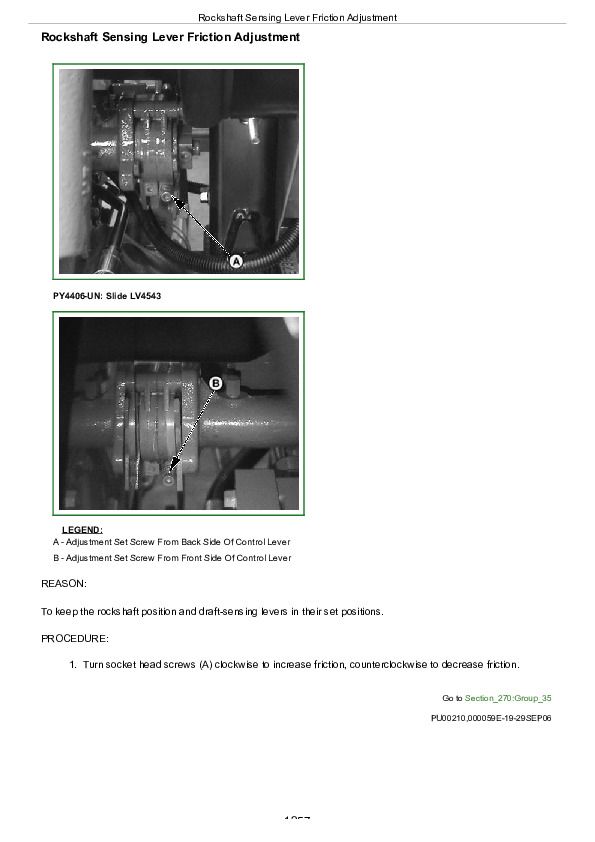
Rockshaft Sensing Lever Friction Adjustment................1257
Control of Assembly of Reaction Spring................1258
Measurement Control of Push rod................1260
Adjustment of Position Control Lever................1261
Adjustment Of Draft Control Lever................1262
Group 40: Adjustments - JD Rockshaft................1181
Rockshaft Lever Friction Adjustment................1264
Rockshaft Position-Sensing Feedback Linkage Adjustment................1265
Rockshaft Draft-Sensing Feedback Linkage Adjustment................1269
Group 21: Hydraulic Schematics................1181
Hydraulic Symbols................1274
John Deere Tractors 5303 & 5403 Diagnostic and Repair Service Manual - TM8208


