John Deere Tractors 5090E, 5085E, 5078E, 5075E, 5065E, 5055E Repair Service Manual (TM801719)
Catalog:
Model:
Complete Repair Service Technical Manual for John Deere Tractors 5055E, 5065E, 5075E, 5078E, 5085E, 5090E (South America, Africa), with all the shop information to maintain, repair, and service like professional mechanics.
John Deere Tractors Models 5055E, 5065E, 5075E, 5078E, 5085E & 5090E workshop technical manual (repair) includes:
* Numbered table of contents easy to use so that you can find the information you need fast.
* Detailed sub-steps expand on repair procedure information
* Numbered instructions guide you through every repair procedure step by step.
* Notes, cautions and warnings throughout each chapter pinpoint critical information.
* Bold figure number help you quickly match illustrations with instructions.
* Detailed illustrations, drawings and photos guide you through every procedure.
* Enlarged inset helps you identify and examine parts in detail.
tm801719 English - John Deere Tractors 5055E, 5065E, 5075E, 5078E (up to serial number -018722), 5085E and 5090E (up to serial number -003438) - (South American Edition) Repair Technical Manual.pdf
tm801728 French - Tracteurs 5055E, 5065E, 5075E, 5078E, 5085E et 5090EManuel de remise en état -: (Édition sud-américaine)
tm801754 Portuguese - Tratores 5055E, 5065E, 5075E, 5078E (até onúmero de série -018722), 5085E e 5090E (até o número de série -003438)—Manual Técnico de Reparos -: (-018722,-003438) -: (Edição América do Sul)
NOTE: TM801719 is Repair Technical Manual only.
For Electrical Wiring Diagrams, please use TM801619 Diagnosis and Test Technical Manual.
Total Pages: 1,064 pages
File Format: PDF (bookmarked, ToC, Searchable, Printable)
Language: English
MAIN SECTIONS
Foreword
General Information
safety
Service Recommendations
General Specifications
Serial Number Locations
Engine Repair
Engine
Cooling System
Fuel and Air Intake System
Fuel System
Air Intake System
Speed Control Linkage
Repairing the Electrical System
Battery, Starter Motor and Alternator
Electrical System Components
Wiring Harness
Repairing the Drive Train
Clutch Housing - TSS Transmission
LUK Clutch Assembly
Transmission
PTO Drive Shaft
Differential
Final Drives
Front-Wheel Drive Actuation
Creeper Transmission
Repairing Steering and Brakes
Repairing the Steering
Repairing the Brakes
Hydraulic Repair
Hydraulic Pump and Filter
Hydraulic Supply/Return Lines
Hydraulic Oil Cooler
Pick-Up Hitch
Pick-Up Hitch - A-Type
Pick-Up Hitch - B-Type
Pick-Up Hitch - C-Type
Pick-Up Hitch - D-Type
Selective Control Valve
Selective Control Valve - A-Type
Selective Control Valve - B-Type
Selective Control Valve - C-Type
Selective Control Valve - D-Type
Third Selective Control Valve - Open Operator's Station
Miscellaneous Repair
3-Point Hitch
Fenders
Hood
Operator's Station
Seat and Support
Control Console and Panel
Roll-Over Protective Structure - ROPS
Cab Components
Air Conditioning System
Heating System
Dealer-Fabricated Tools
TABLE OF CONTENTS
Section 10: General Information................18
Group 05: safety................18
Recognize Safety Information................21
Understand Signal Words................22
Follow Safety Instructions................23
Handle Fluids Safely—Avoid Fires................24
Prevent Battery Explosions................187
Avoid Static Electricity Risk When Refueling................26
Prepare for Emergencies................28
Prevent Acid Burns................29
Service Cooling System Safely................31
Handle Chemical Products Safely................32
Avoid High-Pressure Fluids................33
Park Machine Safely................34
Support Machine Adequately................35
Wear Protective Clothing................36
Work in Clean Area................37
Service Machines Safely................38
Work In Ventilated Area................39
Illuminate Work Area Safely................40
Replace Safety Signs................41
Use Proper Lifting Equipment................42
Keep ROPS Installed Properly................43
Service Tires Safely................44
Avoid Harmful Asbestos Dust................45
Avoid Heating Near Pressurized Fluid Lines................46
Remove Paint Before Welding or Heating................47
Use Proper Tools................281
Dispose of Waste Properly................49
Live With Safety................50
Group 10: Service Recommendations................18
Metric Bolt and Screw Torque Values................53
Unified Inch Bolt and Screw Torque Values................55
Flat Face Seal Fittings Assembly and Installation—All Pressure Applications................58
Metric Face Seal Fitting Torque Chart—Standard Pressure Applications................59
Metric Face Seal Fitting Torque Chart—High Pressure Applications................61
SAE Face Seal Fitting Torque Chart—Standard Pressure Applications................63
SAE Face Seal Fitting Torque Chart—High Pressure Applications................65
External Hex Plug Torque Chart................67
Prevent Hydraulic System Contamination................69
Group 15: General Specifications................988
Machine Specifications—5055E and 5065E Tractors................74
Machine Specifications—5075E, 5078E, 5085E and 5090E Tractors................78
Group 20: Serial Number Locations................19
Serial Numbers................86
Product Identification Number Location................87
Engine Serial Number Location................88
Fuel Injection Pump Serial Number Location................89
Alternator Identification Number Location................90
Power Steering Valve Serial Number Location................91
Transmission Serial Number Location................92
4x2 Front Axle Serial Number—CARRARO................19
4x2 Front Axle Serial Number—DANA................19
4x4 Front Axle Serial Number—DANA................19
4x4 Front Axle Serial Number—ZF................19
Operator's Cab Serial Number................97
Section 70: Hydraulic Repair................591
Group 05: Hydraulic Pump and Filter................98
Essential or Recommended Tools................979
Service Parts Kit................597
Specifications................988
Removing and Installing Hydraulic Pump................599
Removing External Hydraulic Pump Components................601
Disassembling Hydraulic Pump................603
Assembling Bosch Hydraulic Pump................606
Removing, Inspecting and Installing Hydraulic Oil Collector Screen................612
Removing and Installing Hydraulic Filter/Tubing................614
Group 05A: Hydraulic Supply/Return Lines................98
Identifying Hydraulic Supply/Return Line Types................616
Inspecting and Replacing Hydraulic Return/Supply Lines - A-Type................617
Inspecting and Replacing Hydraulic Return/Supply Lines - B-Type................619
Group 05B: Hydraulic Oil Cooler................98
Removing and Installing Hydraulic Oil Cooler................623
Group 10: Hydraulic Hitch................98
Other Materials................626
Service Parts Kits................989
Identification of Hydraulic System Type................628
Group 10A: Pick-Up Hitch - A-Type................98
Inspecting and Repairing Pick-Up Hitch Control Lever Assembly................735
Inspecting and Repairing Pick-Up Hitch Control Lever Mechanism................744
Inspecting and Repairing Draft Sensor Support Assembly................748
Replacing Main Relief Valve................750
Removing, Inspecting and Installing Pick-Up Hitch Rate-of-Drop Control Valve................754
Replacing Pick-Up Hitch Control Valve................757
Adjust Control Valve Sensitivity................656
Removing and Installing Pick-Up Hitch Housing................760
Removing, Inspecting and Installing Pick-Up Hitch Arms................763
Hitch Arms - Attaching................726
Removing, Inspecting and Installing Pick-up Hitch Cylinder and Piston................765
Group 10B: Pick-Up Hitch - B-Type................99
Inspecting and Repairing Pick-Up Hitch Control Lever Assembly................735
Inspecting and Repairing Pick-Up Hitch Control Lever Mechanism................744
Inspecting and Repairing Draft Sensor Support Assembly................748
Replacing Main Relief Valve................750
Replacing Pick-Up Hitch Pressure Relief Valve................752
Removing, Inspecting and Installing Pick-Up Hitch Rate-of-Drop Control Valve................754
Replacing Pick-Up Hitch Control Valve................757
Removing and Installing Pick-Up Hitch Housing................760
Removing, Inspecting and Installing Pick-Up Hitch Arms................763
Hitch Arms - Attaching................726
Removing, Inspecting and Installing Pick-up Hitch Cylinder and Piston................765
Group 10C: Pick-Up Hitch - C-Type................99
Inspecting and Repairing Pick-Up Hitch Control Lever Assembly................735
Inspecting and Repairing Pick-Up Hitch Control Lever Mechanism................744
Inspecting and Repairing Draft Sensor Support Assembly................748
Replacing Main Relief Valve................750
Replacing Pick-Up Hitch Pressure Relief Valve................752
Removing, Inspecting and Installing Pick-Up Hitch Rate-of-Drop Control Valve................754
Replacing Pick-Up Hitch Control Valve................757
Removing and Installing Pick-Up Hitch Housing................760
Removing, Inspecting and Installing Pick-Up Hitch Arms................763
Hitch Arms - Attaching................726
Removing, Inspecting and Installing Pick-up Hitch Cylinder and Piston................765
Group 10D: Pick-Up Hitch - D-Type................99
Inspecting and Repairing Pick-Up Hitch Control Lever Assembly................735
Adjusting Hydraulic Hitch Control Lever Friction................740
Inspecting and Repairing Hydraulic Hitch Control Cables and Links................741
Adjusting Hydraulic Hitch Control Cables................743
Inspecting and Repairing Pick-Up Hitch Control Lever Mechanism................744
Inspecting and Repairing Draft Sensor Support Assembly................748
Replacing Main Relief Valve................750
Replacing Pick-Up Hitch Pressure Relief Valve................752
Removing, Inspecting and Installing Pick-Up Hitch Rate-of-Drop Control Valve................754
Replacing Pick-Up Hitch Control Valve................757
Removing and Installing Pick-Up Hitch Housing................760
Removing, Inspecting and Installing Pick-Up Hitch Arms................763
Removing, Inspecting and Installing Pick-up Hitch Cylinder and Piston................765
Group 15: Selective Control Valve................100
Other Material................987
Service Parts Kits................989
Identifying Selective Control Valve Type................771
Group 15A: Selective Control Valve - A-Type................100
Inspecting and Repairing SCV Lever and Linkage................851
Removing and Installing Single Selective Control Valve (SCV)................776
Inspecting and Replacing Hydraulic Hoses— Single Selective Control Valve................793
Installing Second Selective Control Valve (SCV)................782
Inspecting and Replacing Hydraulic Hoses— Dual Selective Control Valve................786
Group 15B: Selective Control Valve - B-Type................100
Inspecting and Repairing SCV Lever and Linkage................851
Removing and Installing Selective Control Valve (SCV)................789
Inspecting and Replacing Hydraulic Hoses— Single Selective Control Valve................793
Group 15C: Selective Control Valve - C-Type................100
Inspecting and Repairing SCV Lever and Linkage................851
Remove and Install Dual Selective Control Valve (SCV)................796
Disassemble, Inspect, and Assemble Dual Selective Control Valve (SCV)................799
Inspecting and Replacing Hydraulic Hoses—Double Selective Control Valve................803
Group 15D: Selective Control Valve - D-Type................100
Other Material................987
Specifications................988
Inspecting and Repairing Selective Control Valve Levers and Linkages................809
Adjusting Selective Control Valve Lever Cables................812
Removing and Installing Dual Selective Control Valve (SCV)—Standard................813
Removing and Installing Triple Selective Control Valve (SCV)—Deluxe................817
Power Beyond Fitting................820
Disassembling, Inspecting and Assembling Double Selective Control Valve (SCV)—Standard................821
Cross-Sectional View of Triple Selective Control Valve (SCV)—Deluxe................828
Disassembling, Inspecting, and Assembling Triple Selective Control Valve (SCV)—Deluxe................830
Adjusting Kick-Out Pressure of Triple SCV Detent—Deluxe................845
Group 16: Third Selective Control Valve - Open Operator's Station................101
Other Material................987
Inspecting and Repairing SCV Lever and Linkage................851
Removing and Installing Third Selective Control Valve................852
Disassembling, Checking and Assembling Third Selective Control Valve................854
Inspecting and Replacing Hydraulic Hoses—Third Selective Control Valve................856
Section 30: Fuel and Air Intake System................149
Group 05: Fuel System................149
Repairing Injection Pump, Nozzle and Control – Use CTM................151
Removing, Inspecting and Installing Fuel Tank - Open Operator's Station................152
Removing, Inspecting and Installing Fuel Tank - Cab Tractor................155
Replacing Fuel Filter................159
Bleeding Fuel System................160
Removing and Installing Fuel Filter/Primer Pump Assembly................163
Replacing Fuel Line Filter................164
Replacing Fuel Shut-Off Knob................165
Group 10: Air Intake System................149
Repairing Turbocharger – Use Component Technical Manual................167
Specifications................988
Other Material................987
Removing, Inspecting and Installing Air Filter Elements................170
Removing Turbocharger................173
Installing Turbocharger................175
Group 15: Speed Control Linkage................149
Inspecting and Repairing Engine Speed Control Linkage - Open Operator Station................179
Inspecting and Repairing Engine Speed Control Linkage - Cab Tractors................181
Section 40: Repairing the Electrical System................183
Group 05: Battery, Starting Motor and Alternator................183
Starter Repair—Use CTM77................186
Prevent Battery Explosions................187
Removing and Installing the Battery................188
Removing and Installing the Starter Motor................190
Replacing Alternator without Automatic Tightener................191
Replacing Alternator with Automatic Tensioner................193
Group 10: Electrical System Components................183
Essential or Recommended Tools................979
Other Material................987
Specifications................988
Replacing Air Filter Restriction Sensor................199
Replacing Coolant Temperature Sensor................200
Replacing the Engine Speed Sensor................202
Replacing Fuel Shut-Off Solenoid - 4-Cylinder Engines................204
Replacing Engine Oil Pressure Sensor................205
Replacing Ignition Key - 5055E, 5065E and 5075E Tractors................207
Replacing Ignition Key - 5078E, 5085E and 5090E Tractors................209
Replacing Light Switch................211
Replacing Turn Signal Switch................213
Replacing Instrument Panel - 5055E, 5065E and 5075E Tractors................215
Replacing Instrument Panel - 50578E, 5085E and 5090E Tractors - Open Operator's Station................218
Replacing Instrument Panel - 50578E, 5085E and 5090E Tractors - Cab Tractors................220
Replacing Rear PTO Switch................222
Replacing Neutral Start Switch................223
Replacing Fuel Level Sensor - Open Operator's Station................224
Replacing Fuel Level Sensor - Cab Tractors................225
Replacing Windshield Wiper and Washer Switch................226
Replace Fan Control Switch................228
Replacing A/C On/Off Switch................229
Replacing A/C Temperature Control Switch................230
Replacing Fan Motor Resistor................232
Replacing Air Conditioning High/Low Pressure Switch................233
Replacing the Dome Light................234
Replacing Starter Relay................236
Replacing Door Switch................237
Replacing Front Light Bulbs................238
Replacing Front and Rear Work Light Bulbs................240
Replacing Bulbs of Front Turn Signal and Hazard Warning Lights................243
Replacing Bulbs of Rear Turn Signal and Hazard Warning Lights, Taillights, and Brake Lights................245
Replacing Accessory Socket................246
Replacing Power Supply Socket................247
Group 15: Wiring Harness................184
Essential or Recommended Tools................979
Replacing Connector Body—Blade Terminal................250
Replacing the WEATHER PACK WEATHER PACK is a registered trademark of Packard Electric Connector................184
Installing WEATHER PACK WEATHER PACK is a registered trademark of Packard Electric Contact................184
Wiring Harnesses - 5055E and 5065E Tractors................255
Wiring Harnesses - 5075E Tractor................258
Wiring Harnesses - 5078E, 5085E and 5090E Tractors with Open Operator's Station................265
Wiring Harnesses - 5078E, 5085E and 5090E Cab Tractors................268
Replacing Battery Harness................274
Section 50: Repairing the Drive Train................275
Group 05: Clutch Housing — TSS Transmission................275
Practice Safe Maintenance................280
Use Proper Tools................281
Essential or Recommended Tools................979
Other Material................987
Specifications................988
Separating Engine from Clutch Housing - Open Operator's Station................285
Separating Engine from Clutch Housing - Cab Tractors................288
Installing Engine to Clutch Housing - Open Operator's Station................296
Installing Engine to Clutch Housing - Cab Tractor................299
Replacing Clutch Housing Retainer................308
Inspecting and Repairing Clutch Pedal - Open Operator's Station................310
Inspecting and Repairing Clutch Pedal - Cab Tractors................311
Adjusting Clutch Pedal Play................313
Group 10: LUK Clutch Assembly................275
Essential or Recommended Tools................979
Other Material................987
Specifications................988
Clutch Housing Seals................319
Removing and Installing Clutch Assembly................321
Disassembling and Inspecting Clutch Assembly................324
Assembling Clutch................335
Adjusting Drive Clutch Fingers................342
Adjusting PTO Clutch Fingers................344
Group 15: Transmission................275
Other Material................987
Specifications................988
Separating Clutch Housing from Transmission - Open Operator's Station................349
Separating Clutch Housing from Transmission - Cab Tractors................353
Installing Clutch Housing to Transmission - Open Operator's Station................356
Installing Clutch Housing to Transmission - Cab Tractors................360
Inspecting and Repairing Gear Shift Lever - Open Operator's Station................365
Inspecting and Repairing Gear Shift Lever - Open Operator's Station................365
Inspecting and Repairing Range Shift Levers and Gear Shift Levers - Cab Tractors................367
Removing Transmission................369
Disassembling and Inspecting Transmission................373
Assembling the Transmission................379
Installing the Transmission................385
Parking Brake Components................390
Installing Parking Brake Components................395
Removing, Inspecting and Installing Shifter Shaft Assemblies................405
Removing, Inspecting and Installing Upper Transmission Shaft — Transmission with Upper Shaft Synchronization (TSS)................407
Disassemble, Inspect, and Assemble CollarShift Transmission Top Shaft................409
Mounted Upper Shaft................412
Installing Upper Shaft................413
Exploded View of Upper Shaft Collar Shift................424
Disassemble and Inspect Transmission— Collarshift................426
Assemble Transmission — Collarshift................433
Removing, Inspecting and Installing Range Reduction Shaft................440
Removing, Inspecting and Installing Driven Shaft................442
Removing, Inspecting and Installing MFWD and Range Gears................444
Assembling Range Box and MFWD Gears................446
Removing, Inspecting and Installing of Reverse Shaft................452
Group 20: PTO Drive Shaft................276
Essential or Recommended Tools................979
Specifications................988
Inspecting and Repairing PTO Lever and Linkage - Open Operator's Station................457
Inspecting and Repairing PTO Lever and Linkage - Cab Tractors................459
Removing and Installing Standard Rear PTO Drive Shaft Assembly (Standard and 540/540E)................461
Removing, Inspecting and Installing PTO Drive Shaft Assembly................463
Removing, Inspecting and Repairing PTO (540/540E) Lever and Linkage - Open Operator's Station................466
Removing, Inspecting and Installing PTO (540/540E) Lever and Linkage - Cab Tractors................467
Removing, Inspecting and Installing PTO Drive Shaft Assembly (540/540E)................468
Group 25: Differential................277
Essential or Recommended Tools................979
Specifications................988
Service Parts Kits................989
Removing and Installing Differential Assembly................476
Disassembly, Inspection and Assembling of Differential Assembly................478
Removing and Inspecting Differential Drive Shaft................480
Installing Differential Drive Shaft................484
Removing, Inspecting and Installing Differential Lock Assembly - Open Operator's Station................488
Removing, Inspecting and Installing Differential Lock Assembly - Cab Tractors................490
Adjusting Differential Cone End................492
Adjusting Differential Play................494
Group 30: Final Drives................277
Essential or Recommended Tools................979
Other Material................987
Removing and Installing Final Drive Assembly................499
Remove and Inspect Planetary Drive Assembly................501
Installing Planetary Drive Assembly................503
Removing, Inspecting and Installing of Final Drive Shaft Assembly................505
Installing Drive to Center Housing................509
Group 35: Front-Wheel Drive Actuation................277
Essential or Recommended Tools................979
Other Material................987
Inspecting and Repairing MFWD Lever and Linkage - Open Operator's Station................515
Inspecting and Repairing MFWD Lever and Linkage - Cab Tractors................517
Removing and Installing PTO Housing................519
Disassembling and Inspecting MFWD Housing................520
MFWD Housing Cross Sectional View................523
Installing MFWD Creeper Gear Box................525
Removing, Inspecting and Installing MFWD Drive Shaft................530
Removing and Installing Front Axle—ZF................531
Removing and Installing Front Axle—DANA................533
Group 40: Creeper Transmission................277
Removing and Installing Creeper Transmission................538
Disassembling, Inspecting and Assembling Creeper Transmission................540
Final Considerations................542
Bleeding Brakes................543
Section 60: Repairing Steering and Brakes................544
Group 05: Repairing the Steering................544
Other Material................987
Specifications................988
Service Parts Kits................989
Removing and Installing Steering Column and Valve (Without Oil Cooler)................549
Removing and Installing Steering Valve (With Oil Cooler)................551
Removing and Installing Steering Column - Open Operator's Station................553
Removing and Installing Steering Column - Cab Tractors................555
Disassembling and Inspecting Steering Valve................557
Assembling the Steering Valve................561
Inspecting and Replacing Steering Hydraulic Lines (Without Oil Cooler)................567
Inspecting and Replacing Steering Hydraulic Lines (With Oil Cooler)................569
Group 10: Repairing the Brakes................544
Other Material................987
Removing and Installing Brake Valve and Pedals................573
Disassembling and Inspecting Brake Valve................575
Brake Valve Cross Section................578
Assembling the Brake Valve................580
Remove and Inspect Brakes................583
Installing Brakes................586
Inspect and Replace Brake Hydraulic Lines................589
Section 70: Hydraulic Repair................591
Group 05: Hydraulic Pump and Filter................591
Essential or Recommended Tools................979
Service Parts Kit................597
Specifications................988
Removing and Installing Hydraulic Pump................599
Removing External Hydraulic Pump Components................601
Disassembling Hydraulic Pump................603
Assembling Bosch Hydraulic Pump................606
Removing, Inspecting and Installing Hydraulic Oil Collector Screen................612
Removing and Installing Hydraulic Filter/Tubing................614
Group 05A: Hydraulic Supply/Return Lines................591
Identifying Hydraulic Supply/Return Line Types................616
Inspecting and Replacing Hydraulic Return/Supply Lines - A-Type................617
Inspecting and Replacing Hydraulic Return/Supply Lines - B-Type................619
Group 05B: Hydraulic Oil Cooler................591
Removing and Installing Hydraulic Oil Cooler................623
Group 10: Hydraulic Hitch................591
Other Materials................626
Service Parts Kits................989
Identification of Hydraulic System Type................628
Group 10A: Pick-Up Hitch - A-Type................591
Inspecting and Repairing Pick-Up Hitch Control Lever Assembly................735
Inspecting and Repairing Pick-Up Hitch Control Lever Mechanism................744
Inspecting and Repairing Draft Sensor Support Assembly................748
Replacing Main Relief Valve................750
Removing, Inspecting and Installing Pick-Up Hitch Rate-of-Drop Control Valve................754
Replacing Pick-Up Hitch Control Valve................757
Adjust Control Valve Sensitivity................656
Removing and Installing Pick-Up Hitch Housing................760
Removing, Inspecting and Installing Pick-Up Hitch Arms................763
Hitch Arms - Attaching................726
Removing, Inspecting and Installing Pick-up Hitch Cylinder and Piston................765
Group 10B: Pick-Up Hitch - B-Type................592
Inspecting and Repairing Pick-Up Hitch Control Lever Assembly................735
Inspecting and Repairing Pick-Up Hitch Control Lever Mechanism................744
Inspecting and Repairing Draft Sensor Support Assembly................748
Replacing Main Relief Valve................750
Replacing Pick-Up Hitch Pressure Relief Valve................752
Removing, Inspecting and Installing Pick-Up Hitch Rate-of-Drop Control Valve................754
Replacing Pick-Up Hitch Control Valve................757
Removing and Installing Pick-Up Hitch Housing................760
Removing, Inspecting and Installing Pick-Up Hitch Arms................763
Hitch Arms - Attaching................726
Removing, Inspecting and Installing Pick-up Hitch Cylinder and Piston................765
Group 10C: Pick-Up Hitch - C-Type................592
Inspecting and Repairing Pick-Up Hitch Control Lever Assembly................735
Inspecting and Repairing Pick-Up Hitch Control Lever Mechanism................744
Inspecting and Repairing Draft Sensor Support Assembly................748
Replacing Main Relief Valve................750
Replacing Pick-Up Hitch Pressure Relief Valve................752
Removing, Inspecting and Installing Pick-Up Hitch Rate-of-Drop Control Valve................754
Replacing Pick-Up Hitch Control Valve................757
Removing and Installing Pick-Up Hitch Housing................760
Removing, Inspecting and Installing Pick-Up Hitch Arms................763
Hitch Arms - Attaching................726
Removing, Inspecting and Installing Pick-up Hitch Cylinder and Piston................765
Group 10D: Pick-Up Hitch - D-Type................592
Inspecting and Repairing Pick-Up Hitch Control Lever Assembly................735
Adjusting Hydraulic Hitch Control Lever Friction................740
Inspecting and Repairing Hydraulic Hitch Control Cables and Links................741
Adjusting Hydraulic Hitch Control Cables................743
Inspecting and Repairing Pick-Up Hitch Control Lever Mechanism................744
Inspecting and Repairing Draft Sensor Support Assembly................748
Replacing Main Relief Valve................750
Replacing Pick-Up Hitch Pressure Relief Valve................752
Removing, Inspecting and Installing Pick-Up Hitch Rate-of-Drop Control Valve................754
Replacing Pick-Up Hitch Control Valve................757
Removing and Installing Pick-Up Hitch Housing................760
Removing, Inspecting and Installing Pick-Up Hitch Arms................763
Removing, Inspecting and Installing Pick-up Hitch Cylinder and Piston................765
Group 15: Selective Control Valve................593
Other Material................987
Service Parts Kits................989
Identifying Selective Control Valve Type................771
Group 15A: Selective Control Valve - A-Type................593
Inspecting and Repairing SCV Lever and Linkage................851
Removing and Installing Single Selective Control Valve (SCV)................776
Inspecting and Replacing Hydraulic Hoses— Single Selective Control Valve................793
Installing Second Selective Control Valve (SCV)................782
Inspecting and Replacing Hydraulic Hoses— Dual Selective Control Valve................786
Group 15B: Selective Control Valve - B-Type................593
Inspecting and Repairing SCV Lever and Linkage................851
Removing and Installing Selective Control Valve (SCV)................789
Inspecting and Replacing Hydraulic Hoses— Single Selective Control Valve................793
Group 15C: Selective Control Valve - C-Type................593
Inspecting and Repairing SCV Lever and Linkage................851
Remove and Install Dual Selective Control Valve (SCV)................796
Disassemble, Inspect, and Assemble Dual Selective Control Valve (SCV)................799
Inspecting and Replacing Hydraulic Hoses—Double Selective Control Valve................803
Group 15D: Selective Control Valve - D-Type................593
Other Material................987
Specifications................988
Inspecting and Repairing Selective Control Valve Levers and Linkages................809
Adjusting Selective Control Valve Lever Cables................812
Removing and Installing Dual Selective Control Valve (SCV)—Standard................813
Removing and Installing Triple Selective Control Valve (SCV)—Deluxe................817
Power Beyond Fitting................820
Disassembling, Inspecting and Assembling Double Selective Control Valve (SCV)—Standard................821
Cross-Sectional View of Triple Selective Control Valve (SCV)—Deluxe................828
Disassembling, Inspecting, and Assembling Triple Selective Control Valve (SCV)—Deluxe................830
Adjusting Kick-Out Pressure of Triple SCV Detent—Deluxe................845
Group 16: Third Selective Control Valve - Open Operator's Station................594
Other Material................987
Inspecting and Repairing SCV Lever and Linkage................851
Removing and Installing Third Selective Control Valve................852
Disassembling, Checking and Assembling Third Selective Control Valve................854
Inspecting and Replacing Hydraulic Hoses—Third Selective Control Valve................856
Section 80: Miscellaneous Repair................858
Group 15: 3-Point Hitch................858
Inspecting and Repairing Fixed Draft Links (If Equipped with Adjustable Stabilizer Bar)................860
Inspect and Repair Standard Lift Link................861
Inspect and Repair Adjustable Lift Link................863
Inspecting and Repairing Center Link................865
Removing and Installing Drawbar and Support................867
Drawbar and Support (Continued)................869
Group 20: Fenders................858
Removing and Installing Fenders—Open Operator's Station................874
Removing and Installing Fenders - Cab Tractor................878
Group 25: Hood................858
Removing and Installing Hood................886
Section 90: Operator's Station................888
Group 05: Seat and Bracket................888
Removing and Installing Operator's Seat - 5055E, 5065E and 5075E Tractors................892
Removing and Installing Operator's Seat - 5078E, 5085E and 5090E Tractors................893
Removing and Installing Operator's Seat - Cab Tractor................894
Group 06: Control Console and Panel................888
Removing and Installing Console and Right-Hand Instrument Panel - Open Operator's Station................898
Removing and Installing Console and Right-Hand Console - Cab Tractors................901
Removing and Installing Console and Left-Hand Instrument Panel - Open Operator's Station................902
Removing and Installing Left-Hand Panel - Cab Tractors................905
Removing and Installing Console and Left-Hand Console - Cab Tractors................906
Removing and Installing Panel Guard - 5055E, 5065E and 5075E Tractors................907
Removing and Installing Panel Guard - 5078E, 5085E and 5090E Tractors................910
Group 10: Roll-Over Protective Structure — ROPS................888
Removing and Installing ROPS................916
Group 15: Cab Components................888
Essential or Recommended Tools................979
Removing, Inspecting and Installing Cab Air Filters................921
Removing, Inspecting and Installing Cab Air Recirculation Filters................922
Removing and Installing Cab Lining................924
Removing and Installing Front Windshield................927
Remove and Install Front Lower Windows................931
Remove and Install Rear Lower Window................933
Remove and Install Rear Upper Window................935
Removing and Installing Side Windows................936
Removing and Installing Cab Door................938
Remove and Install Cab Outer Roof................941
Removing and Installing Inner Roof of A/C Housing................943
Removing the Cab................954
Installing the Cab................967
Group 20: Air Conditioning System................888
Essential or Recommended Tools................979
Safety Regulations................980
Handling Refrigerant................981
In the event of an Emergency................982
Safety Equipment................983
Storage of Refrigerant Containers................984
R134a Refrigerant................985
Important................986
Other Material................987
Specifications................988
Service Parts Kits................989
Recover/Recycle Air Conditioning Refrigerant................990
Replacing Air Conditioning Receiver-Dryer................991
Remove, Inspect, and Install Air Conditioning Condenser................993
Removing, Inspecting, and Installing Air Conditioning Compressor................997
Compressor Volumetric Efficiency Test................1000
Compressor Shaft Leak Test................1002
Disassembling and Assembling Compressor Clutch................1004
Disassembling Inspecting, and Assembling Compressor................1006
Checking Compressor Clutch Hub Distance................1010
Inspecting Compressor Manifold................1011
Remove and Install Compressor Relief Valve................1012
Accessing HVAC Climatization System................1013
Removing Fan Motors................1014
Removing Heater/Evaporator Core................1015
Evaporator/heater Core Leak Test................1017
Installing Heater/Evaporator Core................1018
Servicing Expansion Valve................1020
Expansion Valve Bench Test................1021
Refrigerant Oil Information................1023
Checking Compressor Oil Charge................1024
Determining Correct Refrigerant Oil Charge................1025
Adding Refrigerant Oil to System................1027
System Information................1028
Cleaning the Air Conditioning System................1029
Evacuating Air Conditioning System................1034
Charging Air Conditioning System................1035
Group 25: Heating System................890
Replacing Heater Control Cable................1039
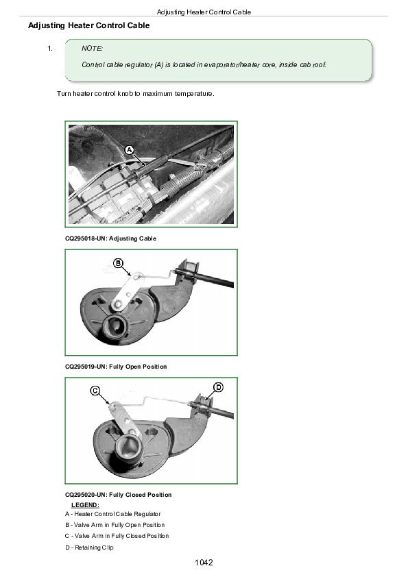
Adjusting Heater Control Cable................1042
Removing Heater Control Valve................1044
Leak Test Heater Control Valve................1045
Installing Heater Control Valve................1046
Section 99: Dealer-Fabricated Tools................1047
Group 00: Dealer-Fabricated Tools................1047
PTO Clutch Finger Height Gauge................1049
Traction Clutch Finger Height Gauge................1050
Traction Clutch Finger Height Adjustment Tool................1051
DFLV1A Final Drive Turning Tool................1052
DFRW20—Compressor Holding Fixture................1053
DFLX13—Holding Device................1054
DFLX15—Holding Device................1055
Axle Support Bushing Installation Tool................1056
U-Joint Shaft Bushing Installation Tool................1057
U-Joint Shaft Link Seal Installation Tool................1058
U-Joint Shaft Link Seal Installation Tool Ring................1059
Wheel Hub Bearing External Cup Mounting Tool................1060
Wheel Hub Sealing Ring Mounting Tool................1061
Wheel Hub Leveling Tool................1062
Pinion Grooved Nut Removal Tool................1063
Splined Shaft Wrench................1064
Pinion Bearing Mounting Tool................1065
Pinion Shaft Seat Seal Mounting Tool................1066
John Deere Tractors 5090E, 5085E, 5078E, 5075E, 5065E, 5055E Repair Service Manual (TM801719)


