John Deere 3029 Diesel Engine - Level 23 ECU Component Technical Manual (CTM120619)
Catalog:
Model:
Complete Component Technical Manual with Electrical Wiring Diagrams for John Deere 3029 Diesel Engine - Level 23 ECU, with all the technical information to maintain, diagnose, repair, rebuild like professional mechanics.
John Deere 3029 Diesel Engine - Level 23 ECU Component Technical Manual includes:
* Numbered table of contents easy to use so that you can find the information you need fast.
* Detailed sub-steps expand on repair procedure information
* Numbered instructions guide you through every repair procedure step by step.
* Troubleshooting and electrical service procedures are combined with detailed wiring diagrams for ease of use.
* Notes, cautions and warnings throughout each chapter pinpoint critical information.
* Bold figure number help you quickly match illustrations with instructions.
* Detailed illustrations, drawings and photos guide you through every procedure.
* Enlarged inset helps you identify and examine parts in detail.
ctm120619 English - 3029 Diesel Engine — Level 23 ECU - (Worldwide Edition) Component Technical Manual.pdf
ctm120628 French - Moteur diesel 3029—Contrôleur ECU niveau 23 -: (Édition mondiale)
ctm120629 German - Dieselmotor 3029 — ECU (Level 23) -: (Weltweite Ausgabe)
ctm120663 Spanish - Motor diésel 3029 — ECU Nivel 23 -: (Edición mundial)
ctm120639 Italian - Motore diesel 3029 – ECU livello 23 -: (Edizione universale)
ctm120654 Portuguese - 3029 Motor a Diesel — Nível 23 ECU -: (Edição Mundial)
PRODUCT DETAILS:
Total Pages: 3,577 pages
File Format: PDF (Internal Links, Bookmarked, Table of Contents, Searchable, Printable, high quality)
TABLE OF CONTENTS
Section 01: General Information................62
Group 000: Safety................62
Understand Signal Words................66
Recognize Safety Information................67
Replace Safety Signs................68
Follow Safety Instructions................69
California Proposition 65 Warning................70
Exhaust Filter Cleaning................71
Avoid Hot Exhaust................72
Work In Ventilated Area................73
Decommissioning — Proper Recycling and Disposal of Fluids and Components................74
Prevent Machine Runaway................75
Practice Safe Maintenance................76
Work in Clean Area................78
Wear Protective Clothing................79
Service Machines Safely................80
Use Proper Tools................81
Construct Dealer-Made Tools Safely................82
Support Machine Properly................83
Use Proper Lifting Equipment................84
Protect Against Noise................85
Illuminate Work Area Safely................86
Install All Guards................87
Stay Clear of Rotating Drivelines................88
Protect Against High Pressure Spray................89
Service Cooling System Safely................90
Remove Paint Before Welding or Heating................91
Precautions for Welding................92
Wait Before Opening High-Pressure Fuel System................94
Avoid High-Pressure Fluids................95
Avoid Heating Near Pressurized Fluid Lines................96
Avoid Static Electricity Risk When Refueling................97
Handle Fluids Safely—Avoid Fires................99
Prepare for Emergencies................100
Handling Batteries Safely................101
Prevent Acid Burns................103
Prevent Battery Explosions................105
Live With Safety................106
Group 001: Engine Identification Information................63
Engine Serial Number Plate Information................109
OEM Engine Option Code Label................111
Emissions Control System Certification Label................113
Information Relative to Emissions Regulations................114
Group 002: Fuels, Lubricants, and Coolants................63
Diesel Fuel................117
Supplemental Diesel Fuel Additives................119
Lubricity of Diesel Fuel................120
Handling and Storing Diesel Fuel................121
Biodiesel Fuel................122
Testing Diesel Fuel................124
Fuel Filters................125
Minimizing the Effect of Cold Weather on Diesel Engines................126
John Deere Break-In Plus™ Engine Oil — Interim Tier 4, Final Tier 4, Stage IIIB, Stage IV, and Stage V................128
Diesel Engine Oil — Interim Tier 4, Final Tier 4, Stage IIIB, Stage IV, and Stage V................129
Diesel Engine Oil and Filter Service Intervals — Interim Tier 4, Final Tier 4, Stage IIIB, Stage IV, and Stage V— OEM Applications................131
Oilscan™ and CoolScan™................133
Diesel Engine Oil and Filter Service Intervals................134
Mixing of Lubricants................135
Alternative and Synthetic Lubricants................136
Lubricant Storage................137
Oil Filters................138
Diesel Engine Coolant (engine with wet sleeve cylinder liners)................139
Water Quality for Mixing with Coolant Concentrate................141
Operating in Warm Temperature Climates................142
Testing Coolant Freeze Point................143
Disposing of Coolant................145
Section 02: Repair and Adjustments................146
Group 010: Engine Rebuild................146
Check Air Intake System................158
Check and Service Cooling System................159
Check Crankcase Vent System................160
Check Electrical System................161
Check Exhaust System................163
Clean Engine................164
Disconnect Turbocharger Oil Supply Line................165
Engine Assembly Sequence................166
Engine Break-In Guidelines................168
Engine Disassembly Sequence................171
Engine Overhaul Guidelines................173
Engine Repair Stand................174
General Tune-Up Recommendations................175
Install Lift Straps................176
Lifting Procedure................178
Safety Precautions................180
Sealant Application Guidelines................181
Group 020: Cylinder Head and Valves................146
Crankcase Pressure Relief Valve — Inspection and Installation................185
Cylinder Block Top Deck — Cleaning and Inspection................187
Cylinder Head — Cleaning and Inspection................188
Cylinder Head — Flatness Check................189
Cylinder Head — Installation................190
Cylinder Head — Removal................195
Cylinder Head — Thickness Measurement................197
Cylinder Head Gasket — Inspection................199
Fuel Injector Heat Shield — Installation................201
Fuel Injector Heat Shield — Removal................202
Fuel Injector Sleeves — Installation................203
Fuel Injector Sleeves — Removal................205
Fuel Supply Pump Push Rod — Installation................214
Fuel Supply Pump Push Rod — Measurement................210
Fuel Supply Pump Push Rod — Removal................216
Push Rod — Cleaning and Inspection................213
Push Rod — Installation................214
Push Rod — Removal................216
Rocker Arm Cover — Inspection................217
Rocker Arm Cover — Installation................218
Rocker Arm Cover — Removal................220
Rocker Arm Shaft Assembly — Assemble................222
Rocker Arm Shaft and Components — Inspection................225
Rocker Arm Shaft Assembly — Installation................227
Rocker Arm Shaft Assembly — Removal................229
Rocker Arm Shaft Assembly — Tear Down................231
Valve Assembly — Installation................233
Valve Assembly — Removal................235
Valve — Cleaning and Inspection................237
Valve — Clearance Adjustment................238
Valve — Grinding................242
Valve — Measurement................243
Valve — Recess Measurement................245
Valve Guide — Cleaning................247
Valve Guide — Knurling................248
Valve Guide — Measurement................249
Valve Rotator and Valve Keepers — Inspection................251
Valve Seat — Cleaning and Inspection................252
Valve Seat — Grinding and Measurement................253
Valve Seat Inserts — Installation................255
Valve Seat Inserts — Removal................256
Valve Spring — Inspection and Measurement................259
Group 030: Cylinder Block, Liners, Pistons and Rods Repair and Adjustment................147
Connecting Rod — Center-to-Center Bore Measurement................262
Connecting Rod — General Information................263
Connecting Rod and Cap — Inspection................265
Connecting Rod Bearing — Inspection and Measurement................267
Connecting Rod Bearing — Inspection and Measurement (Rod and Crankshaft in Engine)................269
Connecting Rod Cap Screw — Torque Procedure................271
Connecting Rod Pin Bore — Cleaning and Inspection................273
Connecting Rod Piston Pin Bushing — Installation................274
Connecting Rod Piston Pin Bushing — Removal................276
Cylinder Block — Cleaning and Inspection................277
Cylinder Block Components — Measurement................281
Cylinder Block O-ring — Installation................283
Cylinder Block, Piston, and Rod — Troubleshooting Guide................285
Cylinder Liner — Cleaning................287
Cylinder Liner — Installation................288
Cylinder Liner — Removal................291
Cylinder Liner — Standout Measurement................293
Cylinder Liner — Visual Inspection................297
Cylinder Liner Flange — Measurement................299
Cylinder Liner O-ring Bore — Cleaning................301
Cylinder Liner Packing — Installation................302
Piston — Cleaning................304
Piston — Visual Inspection................305
Piston and Connecting Rod Assembly — Assemble................306
Piston and Connecting Rod Assembly — Installation................308
Piston and Connecting Rod Assembly — Removal................312
Piston and Connecting Rod Assembly — Tear Down................315
Piston Spray Jet — Cleaning and Inspection................316
Piston Spray Jet — Installation................318
Piston Spray Jet — Removal................320
Piston Height — Measurement................322
Piston Pin and Bore — Inspection................323
Piston Pin and Connecting Rod Bushing — Inspection................325
Piston Protrusion — Measurement................327
Piston Rings — Installation................329
Piston Skirt — Measurement................331
Piston to Liner — Clearance Check................332
Group 040: Crankshaft, Main Bearings and Flywheel Repair and Adjustment................149
Auxiliary Drive Pulley — Installation................335
Auxiliary Drive Pulley — Removal................336
Crankshaft — End Play Check................337
Crankshaft — Grinding Specifications................339
Crankshaft — Inspection................340
Crankshaft — Installation................341
Crankshaft — Removal................346
Crankshaft Main Bearing Cap — Installation................348
Crankshaft Main Bearing Cap — Removal................353
Crankshaft Front Oil Seal — Installation................354
Crankshaft Front Oil Seal — Removal................355
Crankshaft Gear — Installation................356
Crankshaft Gear — Removal................358
Crankshaft Grinding — Guidelines................360
Crankshaft Journals and Bearing Assembly — Measurement................362
Crankshaft Main Bearing Cap — Line Bore Specifications................364
Crankshaft Main Bearing Cap — Oil Clearance Check................366
Crankshaft Rear Oil Seal — Installation................367
Crankshaft Rear Oil Seal — Removal................370
Crankshaft Thrust Bearing — Inspection................374
Crankshaft Timing Wheel — Installation................377
Crankshaft Timing Wheel — Removal................379
Crankshaft Pulley — Installation................380
Crankshaft Pulley — Removal................381
Flywheel — Inspection................383
Flywheel — Installation................384
Flywheel — Removal................386
Flywheel Face — Flatness Check................388
Flywheel Housing — Installation................389
Flywheel Housing — Removal................394
Flywheel Pilot Bearing Bore — Concentricity Check................396
Flywheel Ring Gear — Installation................397
Flywheel Ring Gear — Removal................398
Open Crankcase Ventilation System — Inspection................399
Open Crankcase Ventilation System — Installation................400
Open Crankcase Ventilation System — Removal................403
Group 050: Camshaft and Timing Gear Train Repair and Adjustment................150
Camshaft — Installation................407
Camshaft — Measure End Play................409
Camshaft — Removal................410
Camshaft — Visual Inspection................412
Camshaft and Upper Idler Gear — Timing................413
Camshaft Bushing — Replacement................415
Camshaft Follower — Inspection and Measurement................418
Camshaft Follower — Installation................419
Camshaft Follower — Removal................421
Camshaft Gear — Inspection................422
Camshaft Gear — Installation................423
Camshaft Gear — Removal................424
Camshaft Gear-Driven Auxiliary Drive Cover — Installation................425
Camshaft Gear-Driven Auxiliary Drive Cover — Removal................426
Camshaft Journals — Measurement................427
Camshaft Lobes — Height Measurement................429
Camshaft Thrust Plate — Measure Clearance and Thickness................431
Front Plate — Installation................432
Front Plate — Removal................434
Idler Gears — Measure End Play................436
Lower Idler Gear — Check and Replace Components................437
Lower Idler Gear — Installation................439
Lower Idler Gear — Removal................441
Timing Gear Cover — Installation................442
Timing Gear Cover — Removal................444
Timing Gears — Check Backlash................446
Upper Idler Gear — Check and Replace Components................448
Upper Idler Gear — Installation................451
Upper Idler Gear — Removal................452
Group 060: Lubrication System Repair and Adjustment................151
Dipstick Tube and Dipstick — Installation................458
Dipstick Tube and Dipstick — Removal................463
Oil Cooler Assembly — Installation................466
Oil Cooler Assembly — Removal and Inspection................469
Oil Fill Adapter — Installation................472
Oil Fill Adapter — Removal................473
Oil Filter Header — Installation................474
Oil Filter Header — Removal................476
Oil Pan — Installation................478
Oil Pan — Removal................480
Oil Pick-Up Tube — Installation................481
Oil Pick-Up Tube — Removal................482
Oil Pressure Regulating Valve — Installation................483
Oil Pressure Regulating Valve — Removal................485
Oil Pressure Regulating Valve Seat — Replacement................486
Oil Pump and Tube — Installation................488
Oil Pump and Tube — Removal................491
Group 070: Cooling System Repair and Adjustment................151
Belt Tension — Check................494
By-Pass Tube — Installation................496
By-Pass Tube — Removal................498
Coolant Heater — Servicing................499
Coolant Pump — Visual Inspection................501
Coolant Pump — Assemble................502
Coolant Pump — Tear Down................506
Coolant Pump — Installation................509
Coolant Pump — Removal................512
Cooling System — Air Bleeding................513
Cooling System — Deaeration................515
Fan (Fixed Speed Fan) — Installation................517
Fan (Fixed Speed Fan) — Removal................518
Oil Cooler Coolant Tubes — Installation................519
Oil Cooler Coolant Tubes — Removal................521
Thermostat and Housing — Installation................523
Thermostat and Housing — Removal................525
Group 080: Air Intake and Exhaust System Repair and Adjustment................152
Air Heater or Spacer — Installation................528
Air Heater or Spacer — Removal................530
Charge Air Cooler Outlet Elbow — Installation................532
Charge Air Cooler Outlet Elbow — Removal................533
Exhaust Manifold — Installation................534
Exhaust Manifold — Removal................536
Exhaust Throttle — Installation................537
Exhaust Throttle — Removal................539
Exhaust Throttle Bracket — Installation................541
Exhaust Throttle Bracket — Removal................542
Exhaust Throttle Coolant Return Line — Installation................543
Exhaust Throttle Coolant Return Line — Removal................545
Exhaust Throttle Coolant Supply Line — Installation................547
Exhaust Throttle Coolant Supply Line — Removal................549
Extending Turbocharger Life................551
Intake Manifold — Installation................554
Intake Manifold — Removal................556
Low Profile Turbocharger — Installation................557
Low Profile Turbocharger — Removal................559
Low Profile Turbocharger Exhaust Manifold — Installation................561
Low Profile Turbocharger Exhaust Manifold — Removal................564
Turbocharger — Break-In................566
Turbocharger — Failure Analysis................567
Turbocharger — Inspection................570
Turbocharger — Recommendations for Use................576
Wastegate Turbocharger Inlet Hose — Installation................577
Wastegate Turbocharger Inlet Hose — Removal................578
Wastegate Turbocharger — Installation................579
Wastegate Turbocharger — Removal................581
Wastegate Turbocharger Oil Drain Line — Installation................583
Wastegate Turbocharger Oil Drain Line — Removal................585
Wastegate Turbocharger Oil Supply Line — Installation................586
Wastegate Turbocharger Oil Supply Line — Removal................588
Group 090: Electronic Fuel System Repair and Adjustment................153
Electronic Injectors — Cleaning (In Engine)................591
Electronic Injectors — Installation................593
Electronic Injectors — Removal................597
Fuel Leak-Off Line — Installation................600
Fuel Leak-Off Line — Removal................603
Fuel System — Relieve Pressure................605
High-Pressure Common-Rail (HPCR) — Installation................606
High-Pressure Common-Rail (HPCR) — Removal................607
High-Pressure Common-Rail (HPCR) Heat Shield — Installation................608
High-Pressure Common-Rail (HPCR) Heat Shield — Removal................609
High-Pressure Fuel Pump — Disassembling and Reassembling................610
High-Pressure Fuel Pump — Installation................612
High-Pressure Fuel Pump — Removal................615
High-Pressure Fuel Lines — Installation................617
High-Pressure Fuel Lines — Removal................619
Injector Wiring Harness — Installation................710
Injector Wiring Harness — Removal................722
Low-Pressure Fuel Lines — Installation................625
Low-Pressure Fuel Lines — Removal................627
Low-Pressure Fuel Pump — Installation................629
Low-Pressure Fuel Pump — Removal................631
Pressure Limiter — Installation................633
Pressure Limiter — Removal................635
Fuel Filter Header — Installation................636
Fuel Filter Header — Removal................637
Primary Fuel Filter Element — Replace................638
Suction Control Valve — Installation................640
Suction Control Valve — Removal................642
Group 100: OEM Starting and Charging Systems Repair and Adjustment................154
Alternator — Installation................646
Alternator — Removal................648
Alternator — Lower Bracket — Installation................649
Alternator — Lower Bracket — Removal................651
Alternator — Upper Bracket — Installation................653
Alternator — Upper Bracket — Removal................654
Starter Motor — Installation................655
Starter Motor — Removal................657
Group 110: Electrical Engine Control Repair and Adjustment................154
Camshaft Position Sensor — Installation................660
Camshaft Position Sensor — Removal................662
Cold Start Aid Relay — Installation................663
Cold Start Aid Relay — Removal................667
Compressor Inlet Temperature Sensor — Installation................670
Compressor Inlet Temperature Sensor — Removal................671
Crankshaft Position Sensor — Installation................672
Crankshaft Position Sensor — Removal................674
Crankshaft Position Sensor and Harness Cover — Installation................676
Crankshaft Position Sensor and Harness Cover — Removal................677
DPF Differential Pressure Sensor — Installation................678
DPF Differential Pressure Sensor — Removal................681
Engine Control Unit (ECU) — Installation................683
Engine Control Unit (ECU) — Maintenance................685
Engine Control Unit (ECU) — Removal................686
Engine Coolant Temperature Sensor — Installation................687
Engine Coolant Temperature Sensor — Removal................689
Engine Oil Pressure Sensor — Installation................690
Engine Oil Pressure Sensor — Removal................691
Exhaust Filter Temperature Module — Installation................692
Exhaust Filter Temperature Module — Removal................694
Exhaust Manifold Pressure Sensor — Installation................695
Exhaust Manifold Pressure Sensor — Removal................698
Fuel Rail Pressure Sensor — Installation................700
Fuel Rail Pressure Sensor — Removal................703
Fuel Temperature Sensor — Installation................704
Fuel Temperature Sensor — Removal................705
Manifold Air Pressure (MAP) Sensor — Installation................706
Manifold Air Pressure (MAP) Sensor — Removal................707
Manifold Air Temperature (MAT) Sensor — Installation................708
Manifold Air Temperature (MAT) Sensor — Removal................709
Wiring Harness — Installation................710
Wiring Harness — Removal................722
Wiring Harness — Routing................733
Group 112: Connector Repair and Adjustment................735
Connector Repair and Adjustment................735
Installation of Repair Wire Assembly (RWA)................736
Repair AMP® Seal 16 - Type “A” Connectors................745
Repair AMP® Seal 16 - Type “B” Connectors................747
Repair AMP® Seal 16 - Type “C” Connectors................750
Repair Bosch Connectors................752
Repair DEUTSCH Connectors................754
Repair Metri-Pack™ Connectors................758
Repair WEATHER PACK® Connectors................760
Using High-Pressure Washing................761
Group 115: Aftertreatment Devices Repair and Adjustment................155
Diesel Particulate Filter Maintenance and Service................763
Diesel Oxidation Catalyst (DOC) — Cleaning................764
DPF Differential Pressure Sensor Manifold Fittings — Installation................767
DPF Differential Pressure Sensor Manifold Fittings — Removal................768
Exhaust Filter — Assemble................769
Exhaust Filter — Diesel Particulate Filter Ash Handling and Disposal................771
Exhaust Filter — Handling................772
Exhaust Filter — Tear Down and Inspection................774
Exhaust Filter — Cleaning................780
Exhaust Filter — Disposal................781
Exhaust Filter, Brackets, and Piping — Installation................782
Exhaust Filter, Brackets, and Piping — Removal................783
Section 03: Theory of Operation................784
Group 120: Base Engine Operation................784
Engine Sectional View Component Location Diagrams................789
General Engine Operation................791
General Engine Operation — Continued................793
Head Gasket Joint Construction and Operation................794
Group 123: Cooling System................784
Cooling System Component Location Diagrams................798
Cooling System Operation................800
Group 126: Lubrication System................784
Lubrication System Component Location Diagrams................803
Lubrication System Operation................805
Group 130: Electronic Fuel System................784
Electronic Fuel System Component Location Diagram 1................807
Electronic Fuel System Component Location Diagram 2................808
Electronic Fuel System Component Location Diagram 3................809
Electronic Injector (EI) Operation................810
High-Pressure Common-Rail (HPCR) Operation................815
High-Pressure Fuel Pump Operation................816
High-Pressure Fuel System Operation................817
Low-Pressure Fuel Pump Operation................818
Low-Pressure Fuel System Operation................819
Primary Fuel Filter Operation................822
Group 135: Air Intake and Exhaust System................784
Air Intake and Exhaust System Component Location Diagram 1................824
Air Intake and Exhaust System Component Location Diagram 2................825
Air Intake and Exhaust System Operation................826
Cold Start Aid Operation................828
Exhaust Throttle Operation................829
Wastegate Turbocharger Operation................830
Group 137: Aftertreatment System................784
Aftertreatment Component Location Diagram................832
Aftertreatment System Operation................833
Exhaust Filter Operation................834
Group 140: Electronic Control System................785
Analog Throttle................839
B5100 — Fuel Rail Pressure Sensor................840
B5101 — Engine Oil Pressure Sensor................842
B5102 — Exhaust Manifold Pressure Sensor................844
B5104 — Manifold Air Pressure (MAP) Sensor................846
B5109 — DPF Differential Pressure Sensor................848
B5204 — Exhaust Filter Temperature Module................849
B5206 — Manifold Air Temperature (MAT) Sensor................851
B5208 — Engine Coolant Temperature Sensor................853
B5209 — Fuel Temperature Sensor................855
B5214 — Intake Air Temperature (MAT) Sensor................857
B5301 — Crankshaft Position Sensor................859
B5302 — Camshaft Position Sensor................861
Barometric Air Pressure Sensor................863
Combination Throttle................864
Controller Area Network (CAN)................866
Cruise Control Operation................867
Digital Throttle................868
Electrical Component Location Diagram 1................870
Electrical Component Location Diagram 2................871
Electrical Component Location Diagram 3................872
Electrical Component Location Diagram 4................873
Electrical Component Location Diagram 5................874
Engine Control Unit (ECU) System Operation................875
Engine Control Unit (ECU) Temperature Sensor................878
Engine Derate and Shutdown Protection................879
Governor Droop Mode Selection................881
Measuring Pressure................882
Measuring Speed................883
Measuring Temperature................884
Pilot Injection Operation................885
Sensor Supply #1................886
Sensor Supply #2................887
Sensor Supply #3................888
Sensor Supply #4................889
Sensor Supply #5................890
Sensor Supply #6................891
Sensor Supply #7................892
Sensor Supply #8................893
Sensor Supply #9................894
Throttle Adjustments................895
Throttle Offset................896
Throttle Self-Calibration................897
Torque Speed Control (TSC)................898
Y5021 — Fuel Injector Harness................899
Y5002 — Suction Control Valve................901
Y5402 — Exhaust Throttle Actuator................903
Section 04: Diagnostics................905
Group 150: Observable Diagnostics and Tests................905
Abnormal Engine Noise................905
Coolant in Oil or Oil in Coolant................905
ECU Does Not Communicate with Powerview................905
ECU Does Not Communicate with Service ADVISOR................905
ECU Does Not Program with Service ADVISOR................905
Engine Coolant Temperature Below Normal................905
Engine Cranks and Will Not Start................905
Engine Does Not Develop Full Power................905
Engine Emits Excessive Black or Gray Exhaust Smoke................905
Engine Emits Excessive Blue Exhaust Smoke................905
Engine Emits Excessive White Exhaust Smoke................905
Engine Misfires or Runs Irregularly................905
Engine Will Not Crank................905
Excessive Fuel Consumption................905
Excessive Oil Carryover................905
Excessive Oil Consumption................905
Fuel in Coolant................905
Fuel in Oil................905
Group 155: Checks, Tests, and Procedures................905
Aftertreatment Verification Procedure................1102
Air in Fuel Check................1014
CAN Message Not Received................1016
CAN Message Received Error................1018
CAN Message Received Is Incorrect................1020
Carbon Removal Procedure................1023
Charge Air Cooler Test................1025
Cooling System Pressure Test................1027
Crankcase Pressure (Blow-By) Test................1030
Engine Cranking Speed Check................1036
Engine Oil Pressure Check................1038
Exhaust Condition Check................1039
Fuel Rail Cap and Plug Procedure................1050
Fuel Return Line (Leak off) Restriction Check................1052
Fuel Supply Quality Check................1053
Fuel System Bleeding................1055
High-Pressure Fuel System Check................1058
Low-Pressure Fuel System Check................1077
Mechanical Compression Test................1083
Primary CAN Diagnostic Procedure................1084
Problem Not Found Procedure................1091
Short to Voltage Procedure................1093
Terminal Test................1095
Thermostat — Testing................1099
Turbocharger Oil Seal Leak Check................1101
Verification Procedure................1102
Wastegate Turbocharger — Testing................1104
Wiggle Test................1105
Group 160: Diagnostic Instructions and Information................906
Clear Aftertreatment Latched DTC — Test Instructions................1107
Communication Error Test Instructions................1108
Connecting to Service ADVISOR................1109
Control Unit Information and Overview Test................1111
Cylinder Cutout Test Instructions................1113
Cylinder Electronic Compression Test Instructions................1116
Cylinder Misfire Test Instructions................1121
Data Points Used in Service ADVISOR................1123
Diagnostic Gauge — Active DTC Viewing Instructions................1135
Diagnostic Gauge — Data Parameters Viewing Instructions................1137
Diagnostic Gauge — Exhaust Filter Service Recovery Instructions................1140
Diagnostic Gauge — Stored DTC Clearing Instructions................1150
Diagnostic Gauge — Stored DTC Viewing Instructions................1154
Diagnostic Gauge — Stored DTC Viewing Instructions................1154
Diagnostic Test Box — Using................1156
Diagnostic Trouble Code Designations................1165
Digital Multimeter — Using................1169
DOC Calibration — Instructions................1171
DPF Calibration — Instructions................1172
Electrical Circuit Concepts................1173
Electrical Noise — Possible Causes................1179
Electronic Injector — Calibration Information................1180
Engine Control Unit (ECU) — Level Identification................1182
Engine Control Unit (ECU) — Donating this Engine’s ECU to be Used Elsewhere................1183
Engine Control Unit (ECU) — Replacing Current ECU with Another ECU................1187
Engine Control Unit (ECU) — Replacing Current ECU with Another ECU — Cannot Communicate with Current ECU................1189
Engine Control Unit (ECU) — Reprogramming Current ECU................1191
Engine Control Unit (ECU) — Reprogramming Instructions................1192
Engine Hours — Updating Instructions................1194
Engine Overspeed Verification Test................1196
ESM Operator Action Information Decoder — Instructions................1197
Exhaust Temperature Management Test Instructions................1198
Exhaust Throttle — Learn Value Reset Instructions................1199
Harness Diagnostic Mode Test................1200
Interactive Tests and Calibration Results — Printing, Exporting, or Saving Instructions................1202
Internal Data Monitor — Instructions................1203
Keep Electronic Control Unit Connectors Clean................1208
Load Profile Information Test — Instructions................1209
Lost ECU Data Reset Test................1211
Regeneration Abort Source Identification Test — Instructions................1212
Regeneration Failure — Possible Causes................1213
Service Regeneration Instructions................1215
Servicing Electronic Control Units................1217
Snapshot Instructions................1218
Software and Hardware Verification................1220
Trim Options Information................1223
View Non-Clearable DTCs — Test Instructions................1225
Welding Near Electronic Control Units................1226
Group 161: DTC SPN - 000001—000199................908
000028.03 - Digital Throttle Signal Out of Range High................908
000028.04 - Digital Throttle Signal Out of Range Low................908
000028.14 - Digital Throttle Inhibited................908
000029.03 - Secondary Analog Throttle Signal Out of Range High................908
000029.04 - Secondary Analog Throttle Signal Out of Range Low................908
000029.14 - Secondary Analog Throttle Inhibited................908
000091.03 - Primary Analog Throttle Signal Out of Range High................908
000091.04 - Primary Analog Throttle Signal Out of Range Low................908
000091.09 - Primary Analog Throttle Signal Erratic................908
000091.14 - Primary Analog Throttle Inhibited................908
000100.01 - Engine Oil Pressure Signal Extremely Low................908
000100.02 - Engine Oil Pressure is not Zero with Engine Stopped................908
000100.03 - Engine Oil Pressure Signal Out of Range High................908
000100.04 - Engine Oil Pressure Signal Out of Range Low................908
000100.18 - Engine Oil Pressure Signal Moderately Low................908
000102.00 - Manifold Air Pressure Signal Extremely High................908
000102.03 - Manifold Air Pressure Signal Out of Range High................908
000102.04 - Manifold Air Pressure Signal Out of Range Low................908
000102.07 - Manifold Air Pressure Signal In Range Invalid................908
000102.16 - Manifold Air Pressure Signal Moderately High................908
000105.00 - Manifold Air Temperature Signal Extremely High................908
000105.03 - Manifold Air Temperature Signal Out of Range High................908
000105.04 - Manifold Air Temperature Signal Out of Range Low................908
000105.15 - Manifold Air Temperature Signal Slightly High................908
000105.16 - Manifold Air Temperature Signal Moderately High................908
000108.02 - Barometric Pressure Signal Invalid................908
000108.07 - Barometric Pressure Signal Mismatch................908
000110.00 - Engine Coolant Temperature Signal Extremely High................908
000110.03 - Engine Coolant Temperature Signal Out of Range High................908
000110.04 - Engine Coolant Temperature Signal Out of Range Low................908
000110.15 - Engine Coolant Temperature Signal Slightly High................908
000110.16 - Engine Coolant Temperature Signal Moderately High................908
000110.17 - Engine Coolant Temperature Signal Slightly Low................909
000137.00 - Auxiliary Gauge Pressure Reading Extremely High................909
000137.01 - Auxiliary Gauge Pressure Reading Extremely Low................909
000157.01 - Fuel Rail Pressure Signal Extremely Low................909
000157.03 - Fuel Rail Pressure Signal Out of Range High................909
000157.04 - Fuel Rail Pressure Signal Out of Range Low................909
000157.16 - Fuel Rail Pressure Signal Moderately High................909
000157.17 - Fuel Rail Pressure Signal Slightly Low................909
000157.18 - Fuel Rail Pressure Signal Moderately Low................909
000158.12 - ECU Power Down Error................909
000160.02 - Primary Shaft Speed Invalid................909
000168.01 - Unswitched Battery Voltage Extremely Low................909
000168.16 - Unswitched Battery Voltage Moderately High................909
000168.18 - Unswitched Battery Voltage Moderately Low................909
000174.00 - Fuel Temperature Signal Extremely High................909
000174.03 - Fuel Temperature Signal Out Of Range High................909
000174.04 - Fuel Temperature Signal Out Of Range Low................909
000174.16 - Fuel Temperature Signal Moderately High................909
000189.31 - Engine Speed Derate Condition Exists................909
000190.00 - Engine Speed Extremely High................909
000190.16 - Engine Speed Moderately High................909
Group 162: DTC SPN - 000200—000699................909
000237.02 - VIN Security Data Invalid................909
000237.13 - VIN Option Code Security Data Conflict................909
000237.31 - VIN Security Data Missing................909
000443.00 - Auxiliary Gauge Pressure #2 Reading Extremely High................909
000443.01 - Auxiliary Gauge Pressure #2 Reading Extremely Low................909
000611.03 - Injector Drive Shorted to Voltage Source................909
000611.04 - Injector Drive Shorted to Ground................909
000629.11 - ECU Binary Input Error................909
000629.12 - ECU EEPROM Error................909
000629.13 - ECU Boot Block Error................909
000636.02 - Camshaft Position Signal Invalid................909
000636.05 - Camshaft Position Circuit Has High Resistance................910
000636.06 - Camshaft Position Circuit Has Low Resistance................910
000636.08 - Camshaft Position Signal Missing................910
000636.10 - Camshaft Position Signal Rate of Change Abnormal................910
000637.02 - Crankshaft Position Signal Invalid................910
000637.05 - Crankshaft Position Circuit Has High Resistance................910
000637.06 - Crankshaft Position Circuit Has Low Resistance................910
000637.07 - Crankshaft Position and Camshaft Position Signals Out of Sync................910
000637.08 - Crankshaft Position Signal Missing................910
000637.10 - Crankshaft Position Signal Rate of Change Abnormal................910
000640.11 - External Engine Protection Activated................910
000640.31 - External Derate Activated................910
000651.02 - Injector #1 Part Number Data Invalid................910
000651.05 - Injector #1 Circuit Has High Resistance................910
000651.06 - Injector #1 Circuit Has Low Resistance................910
000651.13 - Injector #1 Calibration Fault................910
000651.18 - Injector #1 Not Responding................910
000652.02 - Injector #2 Part Number Data Invalid................910
000652.05 - Injector #2 Circuit Has High Resistance................910
000652.06 - Injector #2 Circuit Has Low Resistance................910
000652.13 - Injector #2 Calibration Fault................910
000652.18 - Injector #2 Not Responding................910
000653.02 - Injector #3 Part Number Data Invalid................910
000653.05 - Injector #3 Circuit Has High Resistance................910
000653.06 - Injector #3 Circuit Has Low Resistance................910
000653.13 - Injector #3 Calibration Fault................910
000653.18 - Injector #3 Not Responding................910
000676.05 - Cold Start Aid Drive Circuit Has High Resistance................910
000676.06 - Cold Start Aid Drive Circuit Has Low Resistance................910
000676.31 - Cold Start Aid Signal Received When Not Expected................910
000695.19 - Unapproved Engine Speed Request................910
Group 163: DTC SPN - 000700—001999................910
000876.05 - A/C System Drive Circuit Has High Resistance................910
000876.06 - A/C System Drive Circuit Has Low Resistance................911
000970.31 - External Shutdown Commanded................911
000971.31 - External Derate Commanded................911
000974.03 - Remote Analog Throttle Signal Out of Range High................911
000974.04 - Remote Analog Throttle Signal Out of Range Low................911
001069.31 - Calculated Tire Size Is Out Of Range................911
001110.31 - Engine Protection System Activated................911
001136.00 - ECU Temperature Signal Extremely High................911
001136.02 - ECU Temperature Signal Invalid................911
001136.16 - ECU Temperature Signal Moderately High................911
001172.03 - Intake Air Temperature Signal Out of Range High................911
001172.04 - Intake Air Temperature Signal Out of Range Low................911
001180.00 - Calculated Turbocharger Turbine Inlet Temperature Extremely High................911
001180.16 - Calculated Turbocharger Turbine Inlet Temperature Moderately High................911
001209.03 - Exhaust Manifold Pressure Signal Out of Range High................911
001209.04 - Exhaust Manifold Pressure Signal Out of Range Low................911
001209.07 - Exhaust Manifold Pressure Mismatch................911
001321.06 - Engine Starter Solenoid Lockout Relay Circuit Has Low Resistance................911
001321.09 - Engine Starter Solenoid Control Request Signal Missing................911
001321.16 - Engine Starter Engaged for Too Long................911
001321.31 - Engine Speed Zero with Starter Solenoid Energized................911
001347.01 - Suction Control Valve Sticking and Fuel Rail Pressure Extremely Low................911
001347.05 - Suction Control Valve Circuit Has High Resistance................911
001347.06 - Suction Control Valve Circuit Has Low Resistance................911
001347.16 - Suction Control Valve Sticking and Fuel Rail Pressure Moderately High................911
001347.18 - Suction Control Valve Sticking and Fuel Rail Pressure Slightly Low................911
001550.05 - Air Conditioner Compressor Current Low................911
001550.06 - Air Conditioner Compressor Current High................911
001569.31 - Engine Power Derate Condition Exists................911
Group 164: DTC SPN - 002000—002299................911
002002.09 - No CAN Message Received From Source Address 2................911
002002.14 - Incorrect CAN Message Received From Source Address 2................911
002002.19 - Communication Error with Source Address 2................911
002003.09 - No CAN Message Received From Source Address 3................912
002003.14 - Incorrect CAN Message Received From Source Address 3................912
002003.19 - Communication Error with Source Address 3................912
002004.09 - No CAN Message Received From Source Address 4................912
002004.14 - Incorrect CAN Message Received From Source Address 4................912
002004.19 - Communication Error with Source Address 4................912
002005.09 - No CAN Message Received From Source Address 5................912
002005.14 - Incorrect CAN Message Received From Source Address 5................912
002005.19 - Communication Error with Source Address 5................912
002006.09 - No CAN Message Received From Source Address 6................912
002006.14 - Incorrect CAN Message Received From Source Address 6................912
002006.19 - Communication Error with Source Address 6................912
002007.09 - No CAN Message Received From Source Address 7................912
002007.14 - Incorrect CAN Message Received From Source Address 7................912
002007.19 - Communication Error with Source Address 7................912
002008.09 - No CAN Message Received From Source Address 8................912
002008.14 - Incorrect CAN Message Received From Source Address 8................912
002008.19 - Communication Error with Source Address 8................912
002009.09 - No CAN Message Received From Source Address 9................912
002009.14 - Incorrect CAN Message Received From Source Address 9................912
002009.19 - Communication Error with Source Address 9................912
002010.09 - No CAN Message Received From Source Address 10................912
002010.14 - Incorrect CAN Message Received From Source Address 10................912
002010.19 - Communication Error with Source Address 10................912
002011.09 - No CAN Message Received From Source Address 11................912
002011.14 - Incorrect CAN Message Received From Source Address 11................912
002011.19 - Communication Error with Source Address 11................912
002012.09 - No CAN Message Received From Source Address 12................912
002012.14 - Incorrect CAN Message Received From Source Address 12................912
002012.19 - Communication Error with Source Address 12................912
002013.09 - No CAN Message Received From Source Address 13................912
002013.14 - Incorrect CAN Message Received From Source Address 13................912
002013.19 - Communication Error with Source Address 13................912
002014.09 - No CAN Message Received From Source Address 14................913
002014.14 - Incorrect CAN Message Received From Source Address 14................913
002014.19 - Communication Error with Source Address 14................913
002015.09 - No CAN Message Received From Source Address 15................913
002015.14 - Incorrect CAN Message Received From Source Address 15................913
002015.19 - Communication Error with Source Address 15................913
002016.09 - No CAN Message Received From Source Address 16................913
002016.14 - Incorrect CAN Message Received From Source Address 16................913
002016.19 - Communication Error with Source Address 16................913
002017.09 - No CAN Message Received From Source Address 17................913
002017.14 - Incorrect CAN Message Received From Source Address 17................913
002017.19 - Communication Error with Source Address 17................913
002018.09 - No CAN Message Received From Source Address 18................913
002018.14 - Incorrect CAN Message Received From Source Address 18................913
002018.19 - Communication Error with Source Address 18................913
002019.09 - No CAN Message Received From Source Address 19................913
002019.14 - Incorrect CAN Message Received From Source Address 19................913
002019.19 - Communication Error with Source Address 19................913
002020.09 - No CAN Message Received From Source Address 20................913
002020.14 - Incorrect CAN Message Received From Source Address 20................913
002020.19 - Communication Error with Source Address 20................913
002021.09 - No CAN Message Received From Source Address 21................913
002021.14 - Incorrect CAN Message Received From Source Address 21................913
002021.19 - Communication Error with Source Address 21................913
002022.09 - No CAN Message Received From Source Address 22................913
002022.14 - Incorrect CAN Message Received From Source Address 22................913
002022.19 - Communication Error with Source Address 22................913
002023.09 - No CAN Message Received From Source Address 23................913
002023.14 - Incorrect CAN Message Received From Source Address 23................913
002023.19 - Communication Error with Source Address 23................913
002024.09 - No CAN Message Received From Source Address 24................913
002024.14 - Incorrect CAN Message Received From Source Address 24................913
002024.19 - Communication Error with Source Address 24................913
002025.09 - No CAN Message Received From Source Address 25................914
Section 05: Tools and Other Materials................2987
Group 170: Special Tools................2875
DFRG9................2881
DFRG11................2883
75240................2885
D01003AA................2886
D01045AA................2887
D01168AA................2888
D01200AA................2889
D01218AA................2890
D01300AA................2891
D05012ST-A................2892
D05104ST................2893
D15001NU................2894
D17015BR................2895
D17024BR................2896
D17527CI................2897
J-35616-20................2898
JD248A................2899
JD254A................2900
JD262A................2901
JDE83................2902
JDE85................2903
JDE138................2904
JDE41296................2905
JDG22................2906
JDG23................2907
JDG360................2908
JDG361................2909
JDG362................2910
JDG363................2911
JDG364................2912
JDG410................2913
JDG451................2914
JDG529................2915
JDG536................2916
JDG675................2917
JDG676................2918
JDG678................2919
JDG680................2920
JDG698A................2921
JDG739B................2922
JDG777................2923
JDG782A................2924
JDG820................2925
JDG839................2926
JDG1145................2927
JDG1449................2928
JDG1571................2929
JDG1649A................2930
JDG1923A................2931
JDG10015................2932
JDG10205................2933
JDG10233................2934
JDG10243................2935
JDG10259................2936
JDG10261................2937
JDG10273................2938
JDG10446................2939
JDG10447................2940
JDG10452................2941
JDG10453................2942
JDG10456................2943
JDG10457................2944
JDG10460................2945
JDG10461................2946
JDG10464................2947
JDG10465................2948
JDG10466................2949
JDG10539A................2950
JDG10631................2951
JDG10824................2952
JDG11005................2953
JDG11019................2954
JDG11100A................2955
JDG11205................2956
JDG11233................2957
JDG11260................2958
JDG11263................2959
JDG11409................2961
JDG11413................2962
JDG11772................2963
JDG11790................2964
JDG11791................2965
JDG11864................2966
JT01682A................2967
JT03115................2968
JT03513C................2969
JT05470................2970
JT05480................2973
JT05697A................2974
JT05719................2975
JT05993................2976
JT07042................2977
JT07253................2978
JT07306................2979
JT30040B................2980
JT30041A................2981
JT30042................2982
KJD10164................2983
RE523854................2984
Group 180: Lubricants, Sealants, and Other Materials................2987
Other Materials................2987
Section 06: Specifications................2989
Group 200: Repair and General OEM Specifications................2989
Metric Bolt and Screw Torque Values................2992
Unified Inch Bolt and Screw Torque Values................2994
Group 210: Diagnostic Specifications................2989
2.9 L Engine Schematic 1................2998
2.9 L Engine Schematic 2................3000
2.9 L Wiring Diagram 1................3003
2.9 L Wiring Diagram 2................3005
2.9 L Wiring Diagram 3................3007
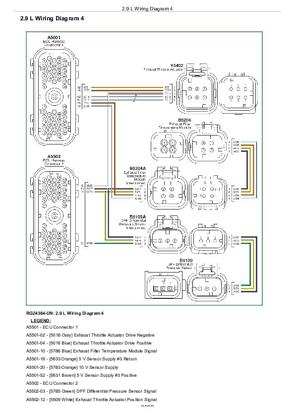
2.9 L Wiring Diagram 4................3009
2.9 L Wiring Diagram 5................3011
2.9 L Wiring Diagram 6................3013
2.9 L Wiring Diagram 7................3016
2.9 L Wiring Diagram 8................3018
2.9 L Wiring Diagram 9................3020
Engine Coolant Temperature and Fuel Temperature Sensor Characteristics................3022
Manifold Air Temperature Sensor Characteristics................3023
OEM Engines - Derate Specifications................3024
Connector and Wire Splice Location Diagrams................3028
John Deere 3029 Diesel Engine - Level 23 ECU Component Technical Manual (CTM120619)


