John Deere Combines Models 9560i STS, 9880 STS, 9880i STS Repair Technical Manual (TM2201)
Catalog:
Model:
Complete Repair manual for John Deere Combines Models 9560i STS, 9880 STS, 9880i STS, with all the shop information to maintain, repair, and rebuild like professional mechanics.
John Deere Combines 9560i STS, 9880 STS, 9880i STS workshop Repair manual includes:
* Numbered table of contents easy to use so that you can find the information you need fast.
* Detailed sub-steps expand on repair procedure information
* Numbered instructions guide you through every repair procedure step by step.
* Troubleshooting and electrical service procedures are combined with detailed wiring diagrams for ease of use.
* Notes, cautions and warnings throughout each chapter pinpoint critical information.
* Bold figure number help you quickly match illustrations with instructions.
* Detailed illustrations, drawings and photos guide you through every procedure.
* Enlarged inset helps you identify and examine parts in detail.
TM2201 English - 9880 STS Combine Technical Manual - Repair.pdf
tm2381 Czech - Opravy sklízecích mlátiček 9560i STS, 9880 STS a 9880i STS
tm9043 French - Moissonneuses-batteuses 9560i STS, 9880 STS 705801 et 9880i STS 710801 Réparation
Total Pages: 2,103 pages
File Format: PDF (bookmarked, ToC, Searchable, Printable)
Language: English...
MAIN SECTIONS
Foreword
General
Safety
Specifications
Tune-Up and Adjustment
Fuels and Lubricants
Engine
Remove and Install Engine
Lower Engine Repair
Cooling System
Fuel and Air Repair
Air Intake System
Diesel Fuel System
Electrical System
Batteries
Harness and Connector Repair
Wire Harness Routing
Fuses, Circuit Breakers and Relays
Lighting
Operators Station
Sensors and Switches
Wiper
Alternator
Starting Motor
GREENSTAR Components (S.N. -705800)
GREENSTAR Components (S.N. 705801-)
Power Train Repair
Transmission and Differential
Single Reduction Final Drive
Hydrostatic System
Cam Lobe Motor
Tires and Wheels
Power Steering and Brakes
Steering
Brakes
Trailer Hitch
Hydraulic Repair
Hydraulic Reservoir
Hydraulic Pumps
Hydraulic Valves
Hydraulic Valve Stack (S.N. -715300)
Hydraulic Valve Stack (S.N. 715301-)
Hydraulic Cylinders
HILLMASTER Cylinders
Accumulator
Hydraulic Motors
Separator Shell
Gull Wing Doors
Operator Station Repair
Air Conditioning System (R134a)
System Components
Cab
Feeder House Repair
Conveyor
Top Shaft and Slip Clutch
Feeder House Drives and Reverser Gear Case
HEADERTRAK Tilt Cylinder and Frame
Separator
Separator Repair
Separator Drives
Residue Disposal
Conveyor Augers, Cleaning Fan And Chaffer And Sieve Frame
Tailings Elevator and Augers
Primary Countershaft Gear Case
Header Electromagnetic Clutch
Grain Tank and Unloading System Repair
Grain Tank Cross Augers
Unloading Auger System Drives
Vertical Unloading Auger and Lower Gear Case
Horizontal Unloading Auger and Gear Case
Horizontal Folding Auger (S.N. 710801-)
Horizontal Auger Elbow and Charge Housing
Clean Grain Elevator
Grain Tank and Covers
Engine Gear Case and Control Valve Repair
Engine Gear Case and Valve
Dealer Fabricated Tools
TABLE OF CONTENTS................1
Section 10: General................32
Group 05: Safety................32
Recognize Safety Information................36
Understand Signal Words................37
Remove Paint Before Welding or Heating................38
Handle Fluids Safely—Avoid Fires................39
Prevent Battery Explosions................258
Handling Batteries Safely................259
Prepare for Emergencies................43
Prevent Acid Burns................44
Avoid High-Pressure Fluids................46
Service Accumulator Systems Safely................47
Wait Before Opening High-Pressure Fuel System................48
Park Machine Safely................49
Support Machine Properly................50
Wear Protective Clothing................51
Service Machines Safely................52
Work In Ventilated Area................53
Illuminate Work Area Safely................54
Replace Safety Signs................55
Use Proper Lifting Equipment................56
Service Tires Safely................877
Avoid Harmful Asbestos Dust................58
Work in Clean Area................59
Practice Safe Maintenance................60
Use Proper Tools................61
Construct Dealer-Made Tools Safely................62
Avoid Heating Near Pressurized Fluid Lines................63
Dispose of Waste Properly................64
Use Adequate Service Facilities................65
Live With Safety................66
Group 10: Specifications................2096
Operating Speeds—9560i STS................70
Operating Speeds—9880 STS and 9880i STS................73
Specifications—9560i STS................76
Specifications—9880 STS and 9880i STS................79
Dimensions—Field Position—9560i STS................82
Dimension Reference Points—Field Position—9560i STS................83
Dimensions—9880 STS (S.N. —710800)................84
Dimension Reference Points 9880 STS (S.N. —710800)................86
Dimensions—Field Position 9880i STS (S.N. —715300)................87
Dimension Reference Points—Field Position 9880i STS (S.N. —715300)................89
Dimensions—Field Position 9880i STS (S.N. 715301—)................90
Dimension Reference Points—Field Position 9880i STS (S.N. 715301—)................92
Dimensions—Transport Position 9560i STS................93
Dimension Reference Points—Transport Position 9560i STS................94
Dimensions—Transport Position 9880i STS (S.N. —715300)................95
Dimension Reference Points—Transport Position 9880i STS (S.N. —715300)................96
Dimensions—Transport Position 9880i STS (S.N. 715301—)................97
Dimension Reference Points—Transport Position 9880i STS (S.N. 715301—)................98
Unified Inch Bolt and Screw Torque Values................99
Metric Bolt and Screw Torque Values................101
Sealants and Adhesives Cross-Reference Chart................103
Face Seal Fittings Assembly and Installation—All Pressure Applications................105
Metric Face Seal Fitting Torque Chart—Standard Pressure Applications................106
Metric Face Seal Fitting Torque Chart—High Pressure Applications................108
SAE Face Seal Fitting Torque Chart—Standard Pressure Applications................110
SAE Face Seal Fitting Torque Chart—High Pressure Applications................112
Four Bolt Flange Fittings Assembly and Installation—All Pressure Applications................114
SAE Four Bolt Flange Cap Screw Torque Values—Standard Pressure Applications................115
SAE Four Bolt Flange Cap Screw Torque Values—High Pressure Applications................116
External Hexagon Port Plug Torque Chart................117
Prevent Hydraulic System Contamination................119
Check Oil Lines and Fittings................120
Basic Electrical Component Handling / Precautions For Vehicles Equipped With Computer Controlled Systems................121
Group 15: Tune-Up and Adjustment................124
Tune-Up and Adjustment................124
Care and Maintenance of Belts................126
Defective Belts................128
Group 20: Fuels and Lubricants................34
Diesel Fuel................133
Heavy Duty Diesel Engine Coolant................135
Supplemental Coolant Additives................136
Storing Fuel................137
Liquid Coolant Conditioner................138
Diesel Engine Break-In Oil................139
Diesel Engine Oil................140
Diesel Engine Oil and Filter Service Intervals................142
Hydrostatic Drive System, Main Hydraulic System and Main Engine Gear Case Oils................144
Transmission, Final Drives, Feeder House Reverser, Loading Auger, Primary Countershaft and Two-Speed Separator Drive Gear Cases................145
Grease................147
Lubricant Storage................149
Alternative and Synthetic Lubricants................150
Section 20: Engine................151
Group 05: Remove and Install Engine................151
Essential or Recommended Tools................2092
Specifications................2096
John Deere Engine Repair................218
Drive Belt Routings—9.0 L Engine................151
Drive Belt Routings—12.5 L Engine................151
Remove Engine—9.0 L................151
Install Engine—9.0 L................151
Remove Engine—12.5 L................151
Install Engine—12.5 L................151
Group 10: Lower Engine Repair................151
Remove and Install Engine Oil Pan Access Sheet................179
Group 15: Cooling System................151
Specifications................2096
John Deere Engine Repair................218
Rotary Screen Drive................184
Remove and Install Rotary Screen Idler Arm and Sheaves................186
Remove and Install Upper and Lower Air Scoops................187
Remove and Install Rotary Screen................189
Remove and Install Rotary Screen Brush Kit................193
Adjusting Rotary Screen Knife Comb................194
Remove Radiator—9.0 L Engine................151
Install Radiator—9.0 L Engine................151
Remove Radiator—12.5 L Engine................151
Install Radiator—12.5 L Engine................151
Test Radiator................210
Test Radiator Cap................211
Replace Thermostats................212
Repair or Replace Water Pump................213
Section 30: Fuel and Air Repair................214
Group 05: Air Intake System................214
Other Material................2095
Specifications................2096
John Deere Engine Repair................218
Remove and Install Turbocharger—9.0 L Engine................214
Remove and Install Turbocharger—12.5 L Engine................214
Turbocharger Repair................225
Remove and Install Charge Air Cooler—9.0 L Engine................214
Remove and Install Charge Air Cooler—12.5 L Engine................214
Cleaning the Charge Air Cooler................235
Group 10: Diesel Fuel System................214
Other Material................2095
Specifications................2096
Bleed Fuel System—12.5 L Engine................214
Remove and Install Fuel Tank Shut-Off Valve and Drain Valve................242
Remove and Install Fuel Prefilter................245
Remove and Install Fuel Tank................246
Remove and Install Fuel Tank Strainer and Breather................249
Section 40: Electrical System................251
Group 05: Batteries................251
Prevent Battery Explosions................258
Handling Batteries Safely................259
Prevent Damage to Electrical Systems................261
Checking Electrolyte Specific Gravity................262
Battery Replacement................264
Remove and Install Batteries................265
Connecting Booster Batteries................269
Charging Batteries................271
Connecting Battery Cables................273
Group 10: Harness and Connector Repair................251
Essential or Recommended Tools................2092
Other Material................2095
Use Electrical Insulating Compound................285
Using High-Pressure Washers................286
Electrical System Visual Inspection................287
Basic Electrical Component Handling / Precautions for Vehicles Equipped with Computer Controlled Systems................288
Electrical Connector / Wiring Harness Handling and Repair................289
Repair Procedure R-A................290
Repair Procedure R-B................295
Repair Procedure R-C................299
Repair Procedure R-D................304
Repair Procedure R-E................307
Repair Procedure R-F................311
Repair Procedure R-G................315
Repair Procedure R-I................318
Repair Procedure R-J................321
Repair Procedure R-K................326
Repair Procedure R-M................329
Repair Procedure R-N................333
Repair Procedure R-AE................337
Repair Procedure R-AF................341
Repair Procedure R-AG................344
Repair Procedure R-AH................347
Repair Procedure R-AI................349
Repair Procedure R-AJ................352
Repair Procedure R-AK................356
Repair Procedure R-AL................359
Group 15: Wire Harness Routing................252
Replace Harness................364
Right-Hand Main Wiring Harness (S.N. —710800)................365
Right-Hand Main Wiring Harness (S.N. 710801—715300)................366
Right-Hand Main Wiring Harness (S.N. 715301—)................367
Left-Hand Main Wiring Harness (S.N. —710800)................368
Left-Hand Main Wiring Harness (S.N. 710801—715300)................369
Left-Hand Main Wiring Harness (S.N. 715301—)................370
Engine Wiring Harness (S.N. —710800)................371
Engine Wiring Harness (S.N. 710801—715300)................372
Engine Wiring Harness (S.N. 715301—)................373
Cab Main Wiring Harness (S.N. —715300)................374
Cab Main Wiring Harness (S.N. 715301—)................375
Auxiliary Cab Main AUTOTRAC Wiring Harness (S.N. —715300)................376
Auxiliary Cab Main AUTOTRAC Wiring Harness (S.N. 715301—)................377
Group 20: Fuses, Circuit Breakers and Relays................252
Engine Compartment Relay Panel Fuse and Relay Identification................380
Control Relay Panel................382
Control Relay Panel Relay Identification................383
Fuse Locations................385
Relay Locations................386
Replace Relays (Central Electronics Box)................387
Replace Relays and Fuses (Engine Compartment Relay Panel)................388
Circuit Board Replacement................389
Group 25: Lighting................252
Safety Rules When Replacing Halogen Bulbs................392
Bulb Part Numbers................393
Cab Head Light Bulb Replacement and Adjustment (S.N. —715300)................394
Cab Head Light Bulb Replacement and Adjustment (S.N. 715301—)................395
Remove and Install High Intensity Discharge (HID-Xenon) Lights (Optional) (S.N. —715300)................397
Remove and Install High Intensity Discharge (HID-Xenon) Lights (Optional) (S.N. 715301—)................400
Remove and Install High Intensity Discharge (HID-Xenon) Ballasts (S.N. 715301—)................403
Auxiliary Field, Access Door, Grain Tank, Unload Auger and Work Light Bulb Replacement................404
Side Finder Light Bulb Replacement................405
Road/Warning Light Bulb Replacement................406
Hazard/Warning Light Bulb Replacement................409
Cleaning Shoe Light Bulb Replacement................411
Turn Signal Light Bulb Replacement................412
Dome and Console Light Bulb Replacement................413
COMMANDTOUCH Cornerpost Monitor Light Bulb Replacement................414
Warning Display Panel Light Bulb Replacement................416
Group 30: Operators Station................253
Other Material................2095
Specifications................2096
Instruments and Controls Identification................421
Overhead Warning Display Panel................423
Remove and Install Overhead Warning Display Panel................425
Replace Overhead Warning Display Panel Circuit Board................427
Remove and Install Light Panel Dimmer Switch................428
Remove and Install Overhead Display Rocker Switches................429
Remove and Install CLIMATRAK Automatic Air Conditioning/Heater Temperature Control Switch and Fan Switch................430
Remove and Install Radio................432
Remove and Install Radio Speaker................433
Remove and Install Radio Antenna................434
Replace Cornerpost Main Circuit Board................436
Remove Header Control Module................440
Remove Automatic Combine Adjustment (ACA) Display................441
Remove Performance Monitor and Digital Tachometer Module................442
COMMANDTOUCH Console Controls................443
Remove and Install COMMANDTOUCH Console................445
Remove and Install Header and Separator Engage Switches................447
Remove and Install DIAL-A-SPEED and Header Height/Ground Pressure Control Switches................448
Remove and Install Back Light Bulbs for DIAL-A-SPEED and Header Height/Ground Pressure Control Switches................450
Remove and Install COMMANDTOUCH Console Membrane Switches................451
Remove and Install CommandTouch Console Circuit Board................457
Replace Neutral Safety Switch................459
Replace Mini Harness................461
Remove and Install Multi-Function Handle................463
Remove and Install Start Switch................464
Remove and Install Turn Signal/Side Finder Light Switch................466
Remove and Install Horn Switch................467
Remove and Install Mirrors................468
Remove and Install Mirror Switch................469
Group 35: Sensors and Switches................254
Other Material................2095
Specifications................2096
Shaft Speed Sensor Locations Right-Hand Side................474
Shaft Speed Sensor Locations Left-Hand Side................475
Remove And Install Low Shaft Speed Sensor................476
Remove and Install STS Rotor Speed Sensor................477
Remove and Install 3/4 Full Remove and Install 3/4 Full & Full Grain Tank Sensor{pgNO}254 Full Grain Tank Sensor................479
Remove and Install Tailings Sensor................480
Remove and Install (Shoe/Separator) VISIONTRAK VISIONTRAK is a trademark of Deere & Company Sensors................254
Remove and Install (Return to Cut and Tilt) Header Height/Ground Pressure Control Sensors................482
Remove and Install Swashplate Sensor................484
Remove and Install Multi-Function Handle Feed Rate Sensor................487
Remove and Install Concave Position Sensor................495
Remove and Install Hydraulic Reservoir Temperature Sensor................496
Remove and Install Hydraulic Reservoir Temperature Sensor (Tier III Cooling Package)................497
Remove and Install Coolant Temperature Sensor................498
Remove and Install Coolant Temperature Sensor (Tier III Cooling Package)................501
Remove and Install Fuel Sender................504
Remove and Install Park Brake Switch................506
Remove and Install Air Filter Restriction Switch................507
Remove and Install Air Filter Restriction Switch (Tier III Cooling Package)................508
Remove and Install Engine Gear Case Temperature and Pressure Switches................509
Remove and Install Hydrostatic Charge Pressure Switch................510
Remove and Install Engine Oil Pressure Switch................511
Remove and Install Fuel Pressure Switch................512
Remove and Install Fuel Temperature Sensor................513
Remove and Install Compressor Inlet Temperature Sensor—9.0 L................514
Remove and Install Front Camshaft Position Sensor—9.0 L................515
Remove and Install Rear Crankshaft Position Sensor—9.0 L................516
Remove and Install Exhaust Gas Recirculation (EGR) Exhaust Gas Temperature, Fresh Air Temperature and Exhaust Manifold Pressure Sensors—9.0 L................517
Remove and Install Intake Manifold Pressure and Exhaust Gas Recirculation (EGR) Mixed Gas Temperature Sensor—9.0 L................518
Remove and Install Turbocharger Speed Sensor—9.0 L................519
Remove and Install Fuel Rail Pressure Sensor—9.0 L................520
Remove and Install Water-In-Fuel Sensor................521
Remove and Install Switches in the Ground Level Switch Bank................522
Remove and Install Back-Up Alarm Switch................523
Back-Up Alarm (S.N. —715300)................524
Back-Up Alarm—9880i (S.N. 715301—)................525
Back-Up Alarm—9560i (S.N. 715301—)................526
Group 40: Wiper................255
Specifications................2096
Remove and Install Wiper................529
Remove and Install Wiper Motor................530
Adjust Windshield Wiper................534
Remove and Install Windshield Washer (S.N. —715300)................536
Remove and Install Windshield Washer (S.N. 715301—)................538
Group 45: Alternator................255
Essential or Recommended Tools................2092
Specifications................2096
John Deere Engine Accessories—Alternator Repair—Use CTM77................543
Remove and Install Alternator and Alternator Belt................544
Remove and Install Voltage Regulator (185 Amp Leece-Neville)................548
Remove and Install Alternator Pulley (200 Amp Bosch)................551
Group 50: Starting Motor................256
Essential or Recommended Tools................2092
Specifications................2096
John Deere Starting Motor Repair—Use CTM77................555
Remove and Install Starting Motor................556
Group 55: GREENSTAR Components (S.N. —705800)................256
Remove and Install GREENSTAR Mass-Flow Sensor................577
Remove and Install GREENSTAR Moisture Sensor................581
Remove and Install GREENSTAR Moisture Sensor Paddle Wheel................569
Remove and Install GREENSTAR Moisture Sensor Motor................570
Remove and Install Position Receiver................592
Group 60: GREENSTAR Components (S.N. 705801—)................256
Specifications................2096
Other Material................2095
Remove and Install GREENSTAR Mass-Flow Sensor................577
Remove and Install GREENSTAR Moisture Sensor................581
Disassemble and Assemble GREENSTAR Moisture Sensor................582
Remove and Install GREENSTAR Moisture Sensor Actuator................584
Remove and Install GREENSTAR Moisture Sensor Circuit Board................588
Disassemble and Assemble Position Receiver................590
Remove and Install Position Receiver................592
Section 50: Power Train Repair................593
Group 05: Transmission and Differential................593
Other Material................2095
Specifications................2096
Remove and Repair Shifter Forks and Shifter Cam................600
Install Shifter Forks and Shifter Cam................602
Remove and Install Transmission Lube Pump................605
Remove and Install Suction Screen................608
Remove Transmission................609
Transmission Recondition................613
Disassemble and Repair Transmission................614
Assemble Transmission................623
Install Transmission................627
Remove and Install Gearshift Lever and Linkage................630
Adjust Gearshift Linkage................632
Group 10: Single Reduction Final Drive................593
Essential or Recommended Tools................2092
Service Equipment and Tools................1686
Other Material................2095
Specifications................2096
Remove and Install Final Drive................641
HILLMASTER Left-Hand Rocker Assembly—Exploded View................647
HILLMASTER Right-Hand Rocker Assembly—Exploded View................649
Disassemble and Assemble Final Drive................651
Adjust Spindle Bearing (Preferred Method)................664
Adjust Spindle Bearing (Alternate Method)................665
Group 15: Hydrostatic System................593
Essential or Recommended Tools................2092
Service Equipment and Tools................1686
Other Material................2095
Specifications................2096
Serial Number Plate................673
Clean Hydrostatic Motor and Pump................674
Flushing the Hydrostatic System................675
Remove and Install Hydrostatic Motor................676
Disassemble Hydrostatic Motor................678
Inspect Parts................689
Lack of Lubrication................690
Abrasive Contamination................691
Cavitation................692
Over Speeding................693
Inspect Thrust Plate................694
Inspect Fixed Swashplate................695
Inspect Piston Slipper................696
Inspect Piston Retainer................698
Inspect Cylinder Block................700
Inspect Bearing Plate................701
Inspect Valve Plate................704
Inspect Bearing and Race................707
Inspect Servo Piston................708
Inspect Drive Shaft................709
Replace Cylinder Block Spring................710
Assemble Motor................711
Remove and Install Motor Valve Block (Manifold)................725
Repair Motor Valve Block................727
Remove and Install Hydrostatic Pump................729
Disassemble Drive Pump................733
Assemble Drive Pump................750
Replace High-Pressure Line Center Pivot O-Rings................770
Disassemble and Assemble End Cover................771
Repair Displacement Control Valve................773
Disassemble and Assemble DisplacementControl Valve with Feed Rate (Optional)................594
Electronic Proportional Displacement Control Valve Neutral Adjustment................777
Remove and Install Charge Pump................781
Repair Charge Pump................783
Remove and Install Control Cable................785
Adjust Hydrostatic Neutral Linkage................787
Adjust Mechanical Displacement Control Valve Neutral................788
Start-Up Procedure After Hydrostatic System Repair................1040
Group 20: Cam Lobe Motor................595
Essential or Recommended Tools................2092
Service Equipment and Tools................1686
Other Material................2095
Specifications................2096
Flushing Cam Lobe Motors................802
Remove Cam Lobe Motor................803
Install Cam Lobe Motor................805
Remove and Install Cam Lobe Motor Control Valve................807
Disassemble and Assemble Cam Lobe Motor Control Valve................810
Remove and Install Steering Yoke................812
Disassemble and Assemble Pivot Pins, Bushings, and Seals................820
Remove and Install Solenoid Valve and Valve Block................823
Remove and Install Displacement Control Valve................828
Remove and Install Cam and Piston Carrier................831
Remove and Install Stack Valve Seals................838
Remove and Install Axle Bearings and Seals—Style A................843
Remove and Install Axle Bearings and Seals—Style B................858
Group 25: Tires and Wheels................595
Essential or Recommended Tools................2092
Service Equipment and Tools................1686
Specifications................2096
Tire Identification................875
Service Tires Safely................877
Care and Service of Tires................878
Using Liquid Weight................880
Jacking Locations................881
Remove and Install Tire................882
Drive Wheel Bolt Torque................884
Rear Wheel Bolt Torque................885
Install Axle Extension Tubes................886
Section 60: Power Steering and Brakes................891
Group 05: Steering................891
Essential or Recommended Tools................2092
Service Equipment and Tools................1686
Other Material................2095
Specifications................2096
Steering Pump Repair................898
Remove Steering Valve................901
Steering Valve................901
Disassemble Steering Valve................903
Assemble Steering Valve................908
Install Steering Valve................914
Electro-Hydraulic Steering Valve and Flowmeter—Exploded View................916
Remove and Install Flowmeter................918
AUTOTRAC Assisted Steering Flowmeter—Exploded View................919
Steering Column Components................920
Disassemble And Assemble Steering Column................922
Replace Telescoping Shaft Bearings................928
Remove and Install Steering Cylinder................930
Bleed Steering Cylinder................934
Steering Cylinder Assembly................935
Disassemble Steering Cylinder................937
Assemble Steering Cylinder................942
Toe-In Adjustment................947
Remove and Install Steering Tie Rod Joint................948
Remove And Install Tie Rod End................949
Remove and Install Rear Spindle Assembly—Non Powered................950
Disassemble and Assemble Rear Spindle Assembly................962
Disassemble and Assemble Rear Spindle Assembly................962
Remove and Install Rear Axle Pivot Bushings................972
Group 10: Brakes................891
Service Equipment and Tools................1686
Other Material................2095
Specifications................2096
Deglazing Brake Linings................980
Remove Brake Drum................981
Remove Brake Shoe................983
Repair Brakes................985
Assemble Brakes................989
Install Brake Drum................991
Remove and Install Master Cylinder................992
Disassemble and Assemble Master Cylinder (Double Bleed Screw)................993
Brake Fluid Reservoir................995
Adjusting Master Cylinder................996
Bleeding Brake System—Double Bleed Screw................997
Remove and Install Slave Cylinders................1002
Disassemble and Assemble Slave Cylinder................1003
Disassemble and Assemble Brake Pedals................1004
Disassemble and Assemble Parking Brake Pedal................1011
Adjust Park Brake Pedal................1020
Group 15: Trailer Hitch................892
Remove and Install Hitch................1022
Section 70: Hydraulic Repair................1023
Group 05: Hydraulic Reservoir................1023
Service Equipment and Tools................1686
Other Material................2095
Specifications................2096
Remove and Install Reservoir (S.N. —715300)................1030
Remove and Install Reservoir (S.N. 715301—)................1033
Flushing the Hydraulic System................1038
Start-Up Procedure After Hydrostatic System Repair................1040
Group 10: Hydraulic Pumps................1023
Essential or Recommended Tools................2092
Service Equipment and Tools................1686
Other Material................2095
Specifications................2096
Remove Triple Main Hydraulic Pump................1046
Marking Triple Main Hydraulic Pump................1048
Disassembling Triple Main Hydraulic Pump................1049
Replace Seal................1051
Triple Main Hydraulic Pump—Exploded View................1052
Assembling Triple Main Hydraulic Pump................1054
Install Triple Main Hydraulic Pump................1056
Reel/Belt Pickup and Chaff Spreader Pump—Exploded View................1057
Reel/Belt Pickup and Straw Spreader Pump—Exploded View................1059
Remove and Install Reel/Belt Pickup Pump Drive................1061
Disassemble and Assemble Reel/Belt Pickup Pump Drive................1065
Remove Chaff Spreader Pump................1070
Install Chaff Spreader Pump................1073
Group 15: Hydraulic Valves................1023
Essential or Recommended Tools................2092
Service Equipment and Tools................1686
Other Material................2095
Specifications................2096
Electro-Hydraulic Feeder House Reverser Valve—General Information................2098
Electro-Hydraulic Feeder House Reverser Valve and Hoses—Exploded View................1081
Electro-Hydraulic Feeder House Reverser Valve—Exploded View................1083
Remove Reel Speed Flow Control Valve................1084
Repair Reel Speed Flow Control Valve................1085
Install Reel Speed Flow Control Valve................1087
Remove and Install Chopper Feed Beater Valve................1088
Remove and Install Chaff Spreader Valve................1089
Reel Reversing Control Valve (S.N. 700801—)................1090
Remove and Install Reel Reversing Control Valve (S.N. 700801—)................1091
Remove and Install Header Height Control Valve................1092
Remove and Install Accumulator Shut-Off Valve................1094
Feeder House Multi-Coupler Valve Identification................1095
Disassemble, Inspect and Assemble Feeder House Multi-Coupler................1096
Group 16: Hydraulic Valve Stack (S.N. —715300)................1024
Service Equipment and Tools................1686
Specifications................2096
Remove and Install Hydraulic Valve Stack................1103
Disassemble and Assemble Hydraulic Valve Stack................1106
Solenoid Control Relief Valve Module................1109
Two-Way Reel Lift and Variable Speed Feeder House Valve Module................1111
Threshing Speed Valve Module................1113
Auger Swing Valve Module................1115
Reel Fore/Aft Valve Module................1117
HEADERTRAK Tilt Valve Module................1119
Hydraulic Solenoid Control Valve Leakage Repair................1121
Replacing Pilot Solenoid Assemblies................1124
Replacing Pilot Sleeve O-Rings................1126
Group 17: Hydraulic Valve Stack (S.N. 715301—)................1024
Service Equipment and Tools................1686
Specifications................2096
Valve Stack Identification................1132
Remove and Install Hydraulic Valve Stack (HIC)................1133
Disassemble and Assemble Hydraulic Valve Stack (HIC)................1135
Group 20: Hydraulic Cylinders................1025
Other Material................2095
Specifications................2096
Remove and Install Header Lift Cylinder................1142
Disassemble and Assemble Header Lift Cylinder................1144
Remove and Install Unloading Auger Swing Cylinder................1146
Unloading Auger Swing Cylinder Exploded View................1148
Adjust Unloading Auger Swing Cylinder................1150
Remove and Install Unloading Auger Drive Cylinder................1152
Group 21: HILLMASTER Cylinders................1025
Other Material................2095
Specifications................2096
HILLMASTER Cylinder Components................1157
Remove and Install Check Valve Components................1159
Compensating Valve Components................1162
Compensating Valve Installed in Piston................1163
Group 25: Accumulator................1025
Essential or Recommended Tools................2092
Accumulator (General Information)................1166
Checking Header Float System Accumulator................1167
Accumulator Precharge Pressure................1170
Group 30: Hydraulic Motors................1025
Remove and Install Chopper Feed Beater Motor................1172
Remove and Install Chaff Spreader Motor—Premium................1173
Section 80: Separator Shell................1175
Group 05: Gull Wing Doors................1175
Other Material................2095
Specifications................2096
Remove and Install Gull Wing Doors................1179
Remove and Install Rear Wall Panel................1181
Remove and Install Rear Access Door................1183
Composite Panel Repair................1185
Align Gull Wing Doors................1189
Remove and Install Engine Platform Ladder................1192
Section 90: Operator Station Repair................1193
Group 05: Air Conditioning System (R134a)................1193
Essential or Recommended Tools................2092
Service Equipment and Tools................1686
Other Material................2095
Specifications................2096
Service Parts Kits................1205
Hose and Tubing O-Ring Connection Torques................1206
Discharge and Recovery of Air Conditioning Refrigerant................1207
Remove and Install Compressor................1208
Test Volumetric Efficiency................1211
Leak Testing Air Conditioning System With Dye................1214
Test Shaft Seal Leakage................1216
Disassemble and Assemble Compressor Clutch................1218
Check Clutch Hub Clearance................1220
Inspect Compressor Manifold................1221
Disassemble, Inspect, and Assemble Compressor................1222
Remove and Install Compressor Relief Valve................1225
System Information................1227
Flush Air Conditioning System................1229
Purge Air Conditioning System................1233
Evacuate Air Conditioning System................1234
Compressor Oil Information................1237
Determine Correct Oil Charge................1238
Check Refrigerant Oil Charge................1240
Charge Air Conditioning System................1241
Group 10: System Components................1193
Essential or Recommended Tools................2092
Other Material................2095
Specifications................2096
Air Conditioning System With Precleaner (General Information)................1246
Remove and Install Receiver/Dryer................1247
Remove and Install Blower Motor—Style A................1248
Remove and Install Blower Motor—Style B................1250
Remove and Install Recirculator Fan Motor Driver—Style A................1251
Remove and Install Recirculator Fan Motor Driver—Style B................1252
Remove and Install Recirculator Motor—Style A................1253
Remove and Install Recirculator Motor—Style B................1254
Replace Heater Control Valve—Style A................1255
Remove and Install Temperature Control Door Actuator—Style B................1258
Remove and Install Heater Core—Style B................1259
Remove Condenser................1261
Remove Condenser—Tier III Cooling Package................1264
Repair Condenser................1267
Install Condenser................1268
Install Condenser—Tier III Cooling Package................1270
Replace Evaporator—Style A................1272
Replace Evaporator—Style B................1274
Replace Expansion Valve—Style A................1276
Replace Expansion Valve—Style B................1277
Remove and Install Evaporator Temperature Sensor—Style A................1279
Remove and Install Evaporator Temperature Sensor—Style B................1281
Replace Low Pressure Switch................1282
Replace High Pressure Switch................1283
Replace Air Temperature Sensors................1284
Group 15: Cab................1194
Specifications................2096
Remove and Install Cab Windshield—Style A................1287
Remove and Install Cab Windshield—Style B................1292
Remove Cab................1300
Install Cab................1309
Replace Rear Window................1317
Remove and Install Cab Roof—Style A................1318
Remove and Install Cab Outer Roof—Style B................1322
Remove and Install Cab Inner Roof—Style B................1324
Remove and Install Cab Headliner—Style B................1330
Remove and Install Operator's Seat................1332
Remove and Install Armrest Control Pivot —Style A................1337
Remove and Install Armrest Control Pivot —Style B................1339
Disassemble and Assemble Armrest Control Pivot—Style A................1341
Remove and Install Operator Presence Switch................1345
Operator Seat—Exploded View................1347
Operator Seat Air Suspension Assembly—Exploded View................1349
Disassemble and Assemble Operator Seat Air Suspension Assembly................1351
Remove and Install Cab Door................1356
Disassemble and Assemble Cab Door................1357
Cab Door Latch Striker................1359
Section 110: Feeder House Repair................1361
Group 05: Conveyor................1361
Essential or Recommended Tools................2092
Other Material................2095
Specifications................2096
Remove and Install Feeder House................1367
Feeder House Conveyor Chain—Adjust................1373
Remove and Install Conveyor Chain................1375
Measure Conveyor Chain Wear................1379
Removing Conveyor Chain Link................1380
Replace Conveyor Chain Slats................1382
Replace Conveyor Chain Wear Strips................1384
Adjust Drum Height................1388
Remove and Install Conveyor Drum................1389
Remove And Install Mid-Floor Assembly................1393
Remove And Install Sub-Floor Assembly................1395
Remove and Install Front Wear Plates................1397
Remove and Install Feed Plate................1400
Adjust Feed Plate Assembly................1403
Feed Plate Support—Exploded View................1405
Group 10: Top Shaft and Slip Clutch................1361
Essential or Recommended Tools................2092
Other Material................2095
Specifications................2096
Remove Top Shaft Slip Clutch................1411
Disassemble and Assemble Top Shaft Slip Clutch................1413
Install Top Shaft Slip Clutch................1418
Remove and Install Top Shaft Supports................1420
Disassemble and Assemble Top Shaft................1424
Group 15: Feeder House Drives and Reverser Gear Case................1361
Other Material................2095
Specifications................2096
Disassemble and Assemble Fixed Speed Countershaft................1437
Remove and Install Reverser Gear Case................1439
Feeder House Reverser Gear Case—Exploded View................1441
Disassemble and Assemble Feeder House Reverser Gear Case................1444
Remove and Install Reverser Shift Piston................1460
Remove and Install Lower Shaft................1464
Disassemble and Assemble Fixed Speed Drive Tightener................1467
Disassemble and Assemble Conveyor Drive Chain, Tightener and Guides................1469
Replace Fixed Speed Feeder House Belt................1471
Group 20: HEADERTRAK Tilt Cylinder and Frame................1362
Other Material................2095
Specifications................2096
HEADERTRAK Tilt Cylinder Hoses and Fittings................1475
HEADERTRAK Tilt Cylinder................1476
Remove and Install HEADERTRAK Tilt Cylinder................1477
Feeder House Shell, Wear Plates and Seal Location Drawings................1479
Tilt Beam and Closure Plates (S.N. —715700)................1480
Tilt Beam and Closure Plates(S.N. 715701—)................1362
Remove and Install Tilt Frame................1484
Remove and Install Tilt Beam (S.N. —700800)................1488
Remove and Install Tilt Beam with Single Point Latching (S.N. 700801—)................1491
Adjust Single Point Latching................1496
Lateral Tilt Beam with Single Point Latching—Exploded View (S.N. 700801—715300)................1499
Lateral Tilt Beam with Single Point Latching—Exploded View (S.N. 715301—)................1500
HILLMASTER Single Point Latching—Exploded View................1501
Adjust Fore-Aft Turnbuckles................1502
Remove Fore-Aft Tilt Frame................1503
Install Fore-Aft Tilt Frame................1508
Section 120: Separator................1514
Group 05: Separator Repair................1514
Essential or Recommended Tools................2092
Other Material................2095
Specifications................2096
Remove and Install Feed Accelerator and Shaft................1525
Remove and Install Feed Accelerator Wear Strips (S.N. —705800)................1532
Remove and Install Feed Accelerator Wear Strips (S.N. 705801—)................1534
Remove and Install Separator Top Covers................1536
Remove and Install Separator Rails................1543
Remove and Install STS Rotor Front Bearing................1554
Remove and Install Stone Trap Door................1559
Remove and Install STS Rotor................1562
Remove and Install STS Rotor Torque Sensing—Driven................1568
Disassemble and Assemble STS Rotor Torque Sensing—Driven................1572
Remove and Install STS Rotor Drive Gear Case................1584
Disassemble and Assemble STS Rotor Drive Gear Case................1588
Remove And Install Discharge Beater Grate Section................1595
Remove And Install Discharge Beater Grate Frame................1600
Remove and Install Discharge Beater................1605
Remove and Install Discharge Beater Drive Hub................1613
Remove and Install Discharge Beater Housing................1615
Remove and Install Separator Grates................1620
Remove and Install Concave Sections................1622
Adjust Concave Level................1631
Remove and Install Concave Adjusting Motor................1637
Remove and Install Concave Adjusting Tube................1638
Repair Separator Rotor Shell................1640
Remove and Install Threshing Elements and Tines................1641
Threshing Element and Separator Tine Location (S.N. —710800)................1645
Threshing Element and Separator Tine Location (15 Element Hi Performance Configuration)................1646
Threshing Element and Separator Tine Location (24 Element Dense Pack Configuration)................1647
Threshing Element and Separator Tine Location—9560i................1648
Remove and Replace RIVNUT Threaded Inserts................1649
Remove and Install STS Rotor Feed Flights................1652
Static Balance STS Rotor................1655
Aligning Rotor Drive Bulkhead................1659
Group 10: Separator Drives................1515
Essential or Recommended Tools................2092
Specifications................2096
Remove and Install Right-Hand Front Jackshaft................1666
Remove and Install Primary Countershaft Bearing................1669
Remove and Install Primary Countershaft—Style A................1672
Remove and Install Primary Drive Shafts................1676
Replace Drive Shaft Carrier Bearing................1682
Group 15: Residue Disposal................1515
Service Equipment and Tools................1686
Other Material................2095
Specifications................2096
Straw Chopper Rotor................1689
Straw Chopper Rotor—Premium................1690
Straw Chopper Housing................1691
Straw Chopper Housing—Premium................1693
Remove Straw Chopper................1695
Remove Straw Chopper—Premium................1698
Remove and Install Chopper Open/Close Actuator—Premium................1700
Remove and Install Chopper Raise/Lower Actuator................1701
Chopper Blades—Replacement And Configuration—9560i................1707
Chopper Blades—Replacement And Configuration—9880 and 9880i................1712
Chopper Blades—Replacement And Configuration—9880i Premium................1717
Install Straw Chopper................1719
Install Straw Chopper—Premium................1722
Remove and Install Chopper Feed Beater Bearings—Premium................1724
Remove and Install Chopper Feed Beater—Premium................1726
Replace Knife Blades (S.N. —715300)................1728
Replace Knife Blades (S.N. 715301—)................1730
Replace Knife Blades—Premium................1731
Remove and Install Easy Adjust Knife Bank................1732
Remove and Install Knife Bank—Premium................1734
Remove and Install Crop Diverter................1735
Replace Left-Hand Chopper Rotor Bearing................1738
Replace Left-Hand Chopper Rotor Bearing—Premium................1743
Replace Right-Hand Chopper Rotor Bearing................1746
Replace Right-Hand Chopper Rotor Bearing—Premium................1748
Remove Straw Chopper Drive Jackshaft—Style A................1749
Install Straw Chopper Drive Jackshaft—Style A................1753
Remove and Install Straw Chopper Drive Jackshaft—Style B................1757
Remove and Install Chopper Drive Clutch—Premium................1762
Straw Chopper Tailboard................1765
Straw Chopper Tailboard—Premium................1767
Straw Chopper Vane Settings................1769
Group 20: Conveyor Augers, Cleaning Fan And Chaffer And Sieve Frame................1516
Other Material................2095
Specifications................2096
Remove and Install Conveyor Auger Drive Shaft................1773
Remove and Install Conveyor Augers................1781
Remove and Install Conveyor Augers................1781
Remove and Install Conveyor Auger Trough................1785
Remove and Install Conveyor Auger Slip Clutch................1787
Remove and Install Cleaning Fan Sheave and Bearing................1788
Fan Drive Speed Control................1794
Remove Cleaning Fan Drive................1796
Disassemble and Assemble Cleaning Fan Drive Jackshaft................1800
Install Cleaning Fan Drive................1801
Adjust Fan Speed Actuator................1804
Remove and Install Cleaning Fan................1805
Remove and Install Cleaning Fan Blade Inserts................1813
Remove and Install Chaffer................1816
Remove and Install Sieve................1818
Remove and Install Remote Shoe Actuator Motor................1820
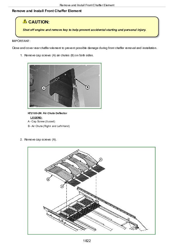
Remove and Install Front Chaffer Element................1822
Remove and Install Chaffer Frame................1824
Remove and Install Sieve Frame................1827
Remove and Install Shake Pan................1829
Remove and Install Shoe Pitman Arms................1832
Group 25: Tailings Elevator and Augers................1517
Specifications................2096
Remove and Install Tailings Paddle Chain................1840
Remove and Install Tailings Paddle................1842
Remove Lower Tailings Auger................1843
Install Lower Tailings Auger................1848
Remove Upper Tailings Auger................1853
Install Upper Tailings Auger................1856
Remove Tailings Elevator................1858
Install Tailings Elevator................1867
Group 30: Primary Countershaft Gear Case................1517
Essential or Recommended Tools................2092
Other Material................2095
Specifications................2096
Remove and Install Primary Countershaft Gear Case................1880
Disassemble and Assemble Primary Countershaft Gear Case................1882
Group 35: Header Electromagnetic Clutch................1517
Specifications................2096
Remove Header Electromagnetic Clutch................1894
Header Electromagnetic Clutch—Exploded View................1896
Install Header Electromagnetic Clutch................1897
Section 130: Grain Tank and Unloading System Repair................1900
Group 05: Grain Tank Cross Augers................1900
Remove Grain Tank Cross Augers (Regular Unload Rate)................1907
Install Grain Tank Cross Augers (Regular Unload Rate)................1911
Remove Grain Tank Cross Augers (High Unload Rate)................1915
Install Grain Tank Cross Augers (High Unload Rate)................1919
Group 10: Unloading Auger System Drives................1900
Specifications................2096
Remove and Install Unloading Auger Drive Belt................1925
Remove and Install Unloading Auger Drive Countershaft—Style A................1926
Remove and Install Unloading Auger Drive Countershaft—Style B................1929
Group 15: Vertical Unloading Auger and Lower Gear Case................1900
Essential or Recommended Tools................2092
Specifications................2096
Remove Vertical Auger Lower Gear Case and Vertical Auger................1935
Disassemble and Assemble Vertical Auger Lower Gear Case-Regular Unload Rate................1939
Install Vertical Auger and Vertical Auger Lower Gear Case................1947
Group 20: Horizontal Unloading Auger and Gear Case................1900
Essential or Recommended Tools................2092
Other Material................2095
Specifications................2096
Inspection of Horizontal Unloading Auger................1955
6.6 Meter (21 Foot) Auger—Two Piece (S.N. —710800)................1900
Remove Horizontal Auger (S.N. —710800)................1958
Install Horizontal Auger (S.N. —710800)................1961
Remove and Install Unloading Auger Grain Saver Door................1983
Horizontal Auger—9560i................1964
Remove Horizontal Auger—9560i................1966
Install Horizontal Auger—9560i................1968
Remove Horizontal Auger Gear Case................1970
Disassemble And Assemble Horizontal Unloading Auger Gear Case................1972
Install Horizontal Auger Gear Case................1977
Remove Horizontal Unloading Auger Tube................1978
Install Horizontal Unloading Auger Tube................1979
Group 25: Horizontal Folding Auger (S.N. 710801—)................1901
Specifications................2096
Other Material................2095
Remove and Install Unloading Auger Grain Saver Door................1983
Folding Horizontal Auger Housing—Exploded View................1984
Folding Horizontal Auger—Exploded View................1986
Folding Horizontal Auger Pivot—Exploded View................1988
Remove and Install Folding Auger Actuator................1990
Remove and Install Outer Folding Auger Assembly................1991
Remove and Install Folding Auger Rings................1993
Remove Horizontal Folding Auger................1994
Remove Horizontal Auger................1995
Install Horizontal Auger................1997
Install Horizontal Folding Auger................2000
Group 30: Horizontal Auger Elbow and Charge Housing................1901
Specifications................2096
Other Material................2095
Unloading Auger Elbow (S.N. —710800)................2004
Unloading Auger Elbow (S.N. 710801—)................2006
Remove Horizontal Auger Elbow................2008
Install Unloading Auger Elbow................2012
Remove Unloading Auger Charge Housing................2015
Install Unloading Auger Charge Housing................2019
Group 35: Clean Grain Elevator................1901
Other Material................2095
Specifications................2096
Adjust Clean Grain Elevator Chain................2025
Remove and Install Clean Grain Paddle Chain................2026
Remove and Install Clean Grain Paddle................2028
Remove Clean Grain Elevator................2029
Install Clean Grain Elevator................2037
Remove and Install Clean Grain Elevator Gear Case................2045
Disassemble and Assemble Clean Grain Elevator Gear Case................2047
Remove and Install Clean Grain Loading Auger Assembly................2054
Remove And Install Clean Grain Loading Auger................2057
Replace Clean Grain Loading Auger Bearing................2061
Remove And Install Lower Clean Grain Auger................2062
Group 40: Grain Tank and Covers................1902
End Grain Tank Covers (S.N. —710800)................2073
End Grain Covers (S.N. 710801—)................2075
Side Grain Tank Covers................2077
Side Grain Tank Covers—HILLMASTER................2081
Side Grain Tank Covers—HILLMASTER................2081
Grain Tank Cover Linkage................2083
Remove and Install Grain Tank Covers................2085
Section 140: Engine Gear Case and Control Valve Repair................2088
Group 05: Engine Gear Case and Valve................2088
Essential or Recommended Tools................2092
Other Material................2095
Specifications................2096
General Information................2098
Remove and Install Engine Gear Case................2099
Engine Gear Case Specifications................2110
Remove and Install STS Rotor Variable Drive................2112
Disassemble and Assemble STS Rotor Variable Drive................2116
Remove and Install STS Rotor Variable Drive Shaft................2126
Remove and Install Transfer Gear Case................2128
Disassemble and Assemble Transfer Gear Case................2133
Disassemble and Assemble Separator Drive Wet Clutch................2137
Disassemble and Assemble Hydrostatic Gear Set................2149
Set Gear Position................2151
Preload Bearings................2164
Disassemble and Assemble Straw Chopper/Unloading System................2157
Set Separator Gear Position................2162
Preload Bearings................2164
Disassemble and Assemble Separator Drive................2166
Preload Separator Drive Bearings................2169
Set Separator Drive Gear Backlash................2171
Disassemble and Assemble Hydrostatic Pump Drive................2172
Preload Hydrostatic Pump Drive Bearings................2174
Set Hydrostatic Pump Drive Gear Backlash................2175
Disassemble and Assemble Oil Screen................2176
Disassemble and Assemble Oil Trough................2177
Disassemble and Assemble Dipstick Tube................2178
Remove and Install Filter................2179
Remove and Install Pressure Regulating Valve................2180
Disassemble and Assemble Pressure Regulating Valve................2182
Section 199: Dealer Fabricated Tools................2187
Group 05: Dealer Fabricated Tools................2187
DFRW20—Compressor Holding Fixture................2189
DFHXT1—Split Ring Tool................2190
DFHXT2—Hydraulic Cylinder Tool................2191


