John Deere POWERTECH® 4.5L & 6.8L Diesel Engines Level 1 Electronic Fuel Systems with Delphi (Lucas) DP201 Pump Component Technical Manual (CTM284)
Catalog:
Model:
John Deere POWERTECH® 4.5L & 6.8L Diesel Engines Level 1 Electronic Fuel Systems with Delphi (Lucas) DP201 Pump Component Technical Manual (including maintenance, overhaul, disassembling & assembling, adjustment, tune-up, operation, inspecting, diagnosis & troubleshooting…) is divided into different sections. Each section covers a specific component or system with detailed illustrations. A table of contents is placed at the beginning of each section. Pages are easily found by category, and each page is expandable for great detail. The printer-ready PDF documents work like a charm on all kinds of devices. This manual contains high quality images, circuit diagrams, instructions to help you to maintenance, troubleshoot, diagnose, and repair. This document is printable, without restrictions, contains searchable text, bookmarks, crosslinks for easy navigation.
CTM284 English - John Deere POWERTECH® 4.5L & 6.8L Diesel Engines Level 1 Electronic Fuel Systems with Delphi (Lucas) DP201 Pump Component Technical Manual.pdf
ctm285 Spanish - Motores diésel POWERTECH® de 4,5 l y 6,8 l Sistemas de combustible electrónicos nivel 1 con bomba Delphi (Lucas) DP201
ctm286 French - Moteurs diesel POWERTECH® 4,5 l et 6,8 l Circuits d'alimentation électroniques niveau 1 avec pompe Delphi (Lucas) DP201
ctm287 German - POWERTECH® 4,5-l- u. 6,8-l- Dieselmotoren mit elektronischen Kraftstoffsystemen der Stufe 1 mit Delphi- (Lucas-) Pumpe DP201
ctm288 Italian - Motori diesel POWERTECH® da 4,5 l e 6,8 l Sistemi di iniezione elettronica livello 1 con pompa Delphi (Lucas) DP201
TABLE OF CONTENTS
Section 01: General................10
Group 000: Safety................10
Handle Fluids Safely — Avoid Fires................12
Handle Starting Fluid Safely................13
Service Cooling System Safely................14
Prevent Battery Explosions................15
Prepare for Emergencies................16
Handling Batteries Safely................17
Avoid High-Pressure Fluids................20
Wear Protective Clothing................21
Service Machines Safely................22
Work In Ventilated Area................23
Work in Clean Area................24
Remove Paint Before Welding or Heating................25
Avoid Heating Near Pressurized Fluid Lines................26
Illuminate Work Area Safely................27
Use Proper Lifting Equipment................28
Construct Dealer-Made Tools Safely................29
Practice Safe Maintenance................30
Use Proper Tools................31
Dispose of Waste Properly................32
Live With Safety................33
Group 001: Engine Identification................10
Engine Model Designation................36
Engine Serial Number Plate Information................38
Engine Application Chart................41
Group 002: Fuels................10
Lubricants and Coolant................43
Diesel Fuel................44
Diesel Fuel Additive Products................45
Bio-Diesel Fuel................46
Lubricity of Diesel Fuel................47
Section 02: Repair and Adjustments................48
Group 090: Electronic Fuel System Repair and Adjustments................48
Fuel System — General Information................51
Relieve Fuel System Pressure................52
Remove and Install Final Fuel Filter/Water Separator Base................53
Final Fuel Filter Assembly................55
Replace Final Fuel Filter/Water Separator................57
Remove Fuel Injection Pump................59
Repair Fuel Injection Pump................63
Install Fuel Injection Pump................64
Fuel Injection Pump Timing................68
Remove Fuel Injection Nozzles................69
Clean Fuel Injection Nozzle Bore................71
Clean Fuel Injection Nozzles................72
Diagnose Fuel Injection Nozzle Malfunction................73
Test Fuel Injection Nozzles................75
Disassemble Fuel Injection Nozzles................80
Inspect and Clean Fuel Injection Nozzle Body................84
Inspect and Clean Valve and Valve Seat................86
Inspect Valve Adjusting Mechanism................88
Assemble Fuel Injection Nozzles................89
Adjust Fuel Injection Nozzles................90
Install Seals on Fuel Injection Nozzle................95
Install Fuel Injection Nozzles................96
Group 110: Electrical Engine Control Repair and Adjustment................48
Engine Control Unit (ECU)................140
Remove and Install Engine Coolant Temperature Sensor................100
Replace Engine Speed Sensor................101
Connectors................102
Use Electrical Insulating Compound................103
Using High-Pressure Washer................104
Repair Weather Pack ™ Connector................105
Remove Connector Body from Blade Terminals................108
Repair (Pull Type) Metri-Pack ® Connectors................109
Repair (Push Type) Metri-Pack ® Connectors................111
Repair Deutsch ® Connectors................114
Repair ECU Connector................117
Repair Fuel Injection Pump Connector................118
Section 03: Theory of Operation................120
Group 130: Electronic Fuel System Operation................123
About this Group................122
Fuel System Operation................123
Fuel Transfer Pump Operation................124
Final Fuel Filter/Water Separator Operation................125
Fuel Injection Pump Operation................127
Fuel Injection Nozzle Operation................129
Group 140: Electrical Control System Operation................120
Electronic Control System Overview................132
Electronic Control System Terminology................133
Electronic Control System Operation................135
Monitoring Engine Parameters................136
Measuring Temperature................137
Measuring Throttle Position................138
Measuring Engine Speed................139
Engine Control Unit (ECU)................140
Controller Area Network (CAN)................142
Cruise Control Operation................143
Governor Droop Mode Selection................441
Engine Control Unit (ECU) Self-Diagnosis................145
Section 04: Diagnostics................146
Group 150: Observable Diagnostics and Tests................146
About this Group of the Manual................224
E1 - Engine Cranks/Won't Start................146
E2 - Engine Misfires/Runs Irregularly................146
E3 - Engine Does Not Develop Full Power................146
E4 - Engine Emits Excessive White Exhaust Smoke................146
E5 - Engine Emits Excessive Black Or Gray Exhaust Smoke................146
E6 - Engine Will Not Crank................146
E7 - Engine Idles Poorly................146
E8 - Abnormal Engine Noise................146
F1 - Fuel Supply System Check................184
F1 - Fuel Supply System Check................184
F2 - Excessive Fuel Consumption................146
F3 - Fuel in Oil................146
F4 - Excessive Fuel Filter Replacement................190
D1 - ECU Does Not Communicate With DST or Service ADVISOR ™................193
D1 - ECU Does Not Communicate With DST or Service ADVISOR ™................193
Using TIME TRAC ® as a Tachometer................198
Check and Adjust Injection Pump Dynamic Timing................199
Check Cold Start Switch Operation................206
Check Cold Start Advance System Operation................207
Check Light Load Advance Operation................209
Test Fuel Shut-Off Solenoid................210
Check Fuel Transfer Pump................211
Check Fuel Supply Quality................212
Test for Fuel Drain Back................214
Test for Air in Fuel................215
Check Fuel Supply Pressure................217
Bleed the Fuel System................218
Test for Cylinder Misfire (Engine Running)................221
Test Fuel Injection Nozzles (Engine Running)................222
Group 160: Trouble Code Diagnostics and Tests................146
About this Group of the Manual................224
Electrical Concepts................225
Using a Digital Multimeter................226
Electrical Circuit Malfunctions................227
Troubleshooting Circuit Malfunctions................230
Connecting to Diagnostic Scan Tool (DST) or Service ADVISOR ™................234
Data Parameter Description................236
Engine Control Unit (ECU) — Level Identification................239
Engine Control Unit (ECU) — Donating this Engines’ ECU to be Used Elsewhere................240
Engine Control Unit (ECU) — Replacing Current ECU with Another ECU................242
Engine Control Unit (ECU) — Replacing Current ECU with Another ECU — Cannot Communicate with Current ECU................244
Engine Control Unit (ECU) — Reprogramming Current ECU................246
Engine Control Unit (ECU) — Reprogramming Instructions................248
Software and Hardware Verification................250
Diagnostic Trouble Codes (DTCs)................253
Listing of Diagnostic Trouble Codes (DTCs) on ECU................254
Diagnostic Procedure................256
Intermittent Fault Diagnostics................257
000028.03 — Analog Throttle (C) Input High................258
000028.03 - Analog Throttle (C) Input High................147
000028.04 — Analog Throttle (C) Input Low................263
000028.04 - Analog Throttle (C) Input Low................147
000029.03 — Analog Throttle (B) Input High................268
000029.03 - Analog Throttle (B) Input High................147
000029.04 — Analog Throttle (B) Input Low................274
000029.04 - Analog Throttle (B) Input Low................147
000091.03 — Analog Throttle (A) Input High................280
000091.03 - Analog Throttle (A) Input High................147
000091.04 — Analog Throttle (A) Input Low................286
000091.04 - Analog Throttle (A) Input Low................147
000091.07 - Throttle Not Calibrated Properly................147
000091.13 - Throttle Calibration Aborted................147
000110.03 — Engine Coolant Temperature Input Voltage High................294
000110.03 - Engine Coolant Temperature Input Voltage High................148
000110.04 — Engine Coolant Temperature Input Voltage Low................298
000110.04 - Engine Coolant Temperature Input Voltage Low................148
000190.00 - Engine Overspeed................148
000190.02 — Engine Speed Input Noise................303
000190.02 - Engine Speed Input Noise................148
000629.04 — ECU Unswitched Power Missing................308
000629.04 - ECU Unswitched Power Missing................148
000639.13 — CAN Error................311
000639.13 - CAN Error - Continued................148
000810.02 — Calculated Vehicle Speed Input Signal Noise................315
000810.02 - Calculated Vehicle Speed Input Signal Noise................148
000931.02 — Pump Current Instability................318
000931.02 - Pump Current Instability................148
000931.03 — Pump Current Feedback Input Voltage High................324
000931.03 - Pump Current Feedback Input Voltage High................148
000931.04 — Pump Current Feedback Input Voltage Low................327
000931.04 - Pump Current Feedback Input Voltage Low................148
000931.15 — Pump Current Measurement Error (Engine OFF)................330
000931.15 - Pump Current Measurement Error (Engine OFF)................148
000931.31 — Pump Current Not Controllable................334
000931.31 - Pump Current Not Controllable................148
001041.02 — Start Signal Missing................340
001041.02 - Start Signal Missing................148
001041.03 — Start Signal Always Active................344
001041.03 - Start Signal Always Active................148
001069.02 — Tire Size Error................348
001069.02 - Tire Size Error................148
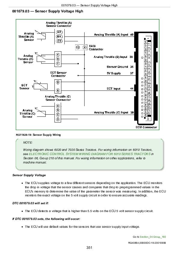
001079.03 — Sensor Supply Voltage High................351
001079.03 - Sensor Supply Voltage High................148
001079.04 — Sensor Supply Voltage Low................355
001079.04 - Sensor Supply Voltage Low................148
002000.13 - Security Violation................149
Section 05: Tools and Other Materials................360
Group 170: Electronic Fuel/Control System Repair Tools and Other Materials................360
Fuel System Repair and Adjustment Essential Tools................363
Fuel System Repair and Adjustment Service Equipment and Tools................365
Fuel System Repair and Adjustment Other Materials................366
Control System Repair and Adjustment Essential Tools................367
Control Repair and Adjustment Other Materials................370
Group 180: Diagnostic Service Tools................360
Engine Diagnostics and Testing Procedure Tools................374
Section 06: Specifications................377
Group 200: Repair Specifications................377
Electronic Fuel System Repair and Adjustment Specifications................380
Electrical Engine Control Repair and Adjustment Specifications................382
Group 210: Diagnostic Specifications................377
Fuel Injection Pump Specifications (Agricultural Applications)................401
Fuel Injection Pump Specifications (OEM)................419
Fuel System Diagnostic Specifications................439
Torque Curve Selection................440
Governor Droop Mode Selection................441
Electronic Control System Wiring Diagram for 6010 Series Tractors................442
Electronic Control System Wiring Diagram for 6020 and 7020 Series Tractors................443
John Deere POWERTECH® 4.5L & 6.8L Diesel Engines Level 1 Electronic Fuel Systems with Delphi (Lucas) DP201 Pump Component Technical Manual (CTM284)


