Case 621F, 721F Wheel Loader Workshop Repair & Service Manual
Catalog:
Model:
Complete repair workshop manual contains service, maintenance, and troubleshooting information for the Case 621F, 721F Wheel Loader. Diagnostics and repair procedures are covered in great detail to repair, maintain, rebuild, refurbish or restore your Case 621F, 721F Wheel Loader like a professional mechanic in local service/repair workshop.This cost-effective quality manual is 100% complete and intact as should be without any missing pages.It is the same factory shop manual used by dealers that guaranteed to be fully functional to save your precious time.
This manual for Case 621F, 721F Wheel Loader is divided into different sections.Each section covers a specific component or system and, in addition to the standard service procedures, includes disassembling, inspecting, and assembling instructions.A table of contents is placed at the beginning of each section.Pages are easily found by category, and each page is expandable for great detail.It is in the cross-platform PDF document format so that it works like a charm on all kinds of devices.You do not need to be skilled with a computer to use the manual.
4,000+ pages, bookmarked, Searchable, Printable, high quality PDF
47387703 - 621F Tier 4 Wheel Loader Service Manual.pdf - 1,090 pages
84474094 - 621F, 721F Tier 4 Wheel Loader Operator's Manual (Replaces part number 84376871).pdf - 363 pages
84487558 - 721F Tier 4 Wheel Loader Service Manual (1-2-4 GeneralInformation_Engine_ElectricalSystem).pdf - 445 pages
84487559 - 721F Tier 4 Wheel Loader Service Manual (5-6 Undercarriage_DriveTrain).pdf - 1305 pages
84487560 - 721F Tier 4 Wheel Loader Service Manual (7-8-9 UndercarriageHydraulics_UpperstructureHydraulics_Upperstructure).pdf - 263 pages
84488413 - 721F Tier 4 Wheel Loader Service Manual.pdf - 1,020 pages
84605841 - 621F, 721F Tier 4 Wheel Loader Service Manual (from PIN NBF213602 and above).pdf - 2,286 pages
Digital PDF format with all its advantages, just like the original paper manuals. Step by step Instructions, illustrations, diagrams for remove and install, assembly and disassembly, service, maintenance, repair, service, operation procedures.
PDF Manual:
Pages: 2286
Instant download: You will receive link for download on your email immediately after payment.
Compatible with PC, MAC/ Tablet / Smartphone
Searchable PDF
NOT a scan
Bookmarks
Printable: pages or entire manual
Zoomable: detailed exploded diagrams, picture
Models
Case 621F 721F Tier 4 Wheel Loaders
PIN NBF213602 and above
Contents
Service Repair Manual (84605841)
2,286 pages
Contents
Introduction
Engine
Transmission
Four-Wheel-Drive (4WD) system
Front axle system
Rear axle system
Brakes and controls
Hydraulic systems
Steering
Wheels
Cab climate control
Electrical systems
Platform, cab, bodywork, and decals
Special Tool Index
Electrical Schematic
Hydraulic Schematic
Operators Manual ( 84474094 )
362 pages
Introduction
Engine
Engine and crankcase
Air cleaners and lines
Engine lubrication system
Aftercooler
Engine cooling system
Fan and drive
Selective Catalytic Reduction (SCR) exhaust treatment
Engine generic sub-group
Transmission
Powershift transmission
Powershift transmission external controls
Powershift transmission internal components
Four-Wheel Drive (WD) system
Drive shaft
Front axle system
Powered front axle
Front bevel gear set and differential
Final drive hub, steering knuckles, and shafts
Rear axle system
Powered rear axle
Rear bevel gear set and differential
Planetary and final drives
Brakes and controls
Hydraulic service brakes
Hydraulic systems
Variable displacement pump
Pilot system
Main control valve
Auxiliary hydraulic valves and lines
Front loader arm hydraulic system
Steering
Auxiliary steering
Wheels
Front wheels
Cab climate control
Air conditioning
Electrical system
Fuel tank system
Engine cooling system
Engine control system
Service brake electrical system
Parking brake electrical system
Hydraulic system control
Steering control system
Heating, Ventilation, and Air-Conditioning (HVAC) control system
Cab Heating, Ventilation, and Air-Conditioning (HVAC) controls
Harnesses and connectors
Engine starting system
Cold start aid
Alternator
Battery
External lighting
External lighting switches and relays
Warning indicators, alarms, and instruments
Loader arm and bucket control system
Cab/Platform harnesses and connectors
Cab controls
Cab lighting
Wiper/Washer system
Cab brake controls
Cab controls (Lift arm, Boom, Dipper, Bucket)
Selective Catalytic Reduction (SCR) electrical system
FAULT CODES DTC
Platform, cab, bodywork, and decals
Pneumatically-adjusted operator seat
Cab
EXCERPT:
Contents
INTRODUCTION
Engine...10
Engine and crankcase...10.001
Air cleaners and lines...10.202
Engine lubrication system ...10.304
Aftercooler ...10.310
Engine cooling system ...10.400
Fan and drive ...10.414
Selective Catalytic Reduction (SCR) exhaust treatment ...10.500
Engine generic sub-group ...10.AAA
Transmission...21
Powershift transmission ...21.113
Powershift transmission external controls ...21.135
Powershift transmission internal components ...21.155
Four-Wheel Drive (4WD) system ...23
Drive shaft ...23.314
Front axle system ...25
Powered front axle ...25.100
Front bevel gear set and differential ...25.102
Final drive hub, steering knuckles, and shafts ...25.108
Rear axle system...27
Powered rear axle ...27.100
Rear bevel gear set and differential ...27.106
Planetary and final drives...27.120
Brakes and controls ...33
Hydraulic service brakes ...33.202
Hydraulic systems...35
Hydraulic systems ...35.000
Variable displacement pump ...35.106
Pilot system...35.357
Main control valve ...35.359
Auxiliary hydraulic valves and lines ...35.525
Front loader arm hydraulic system ...35.701
Steering...41
Auxiliary steering ...41.910
Wheels...44
Front wheels...44.511
Cab climate control ...50
Air conditioning ...50.200
Electrical systems ...55
Electrical system ...55.000
Fuel tank system ...55.011
Engine cooling system ...55.012
Engine control system ...55.015
Service brake electrical system ...55.030
Parking brake electrical system ...55.031
Hydraulic system control ...55.036
Steering control system ...55.047
Heating, Ventilation, and Air-Conditioning (HVAC) control system ...55.050
Cab Heating, Ventilation, and Air-Conditioning (HVAC) controls ...55.051
Harnesses and connectors ...55.100
Engine starting system ...55.201
Cold start aid ...55.202
Alternator ...55.301
Battery ...55.302
External lighting ...55.404
External lighting switches and relays ...55.405
Warning indicators, alarms, and instruments ...55.408
Loader arm and bucket control system...55.415
Cab/Platform harnesses and connectors...55.510
Cab controls ...55.512
Cab lighting ...55.514
Wiper/Washer system ...55.518
Cab brake controls ...55.519
Cab controls (Lift arm, Boom, Dipper, Bucket) ...55.524
Selective Catalytic Reduction (SCR) electrical system...55.988
FAULT CODES ...55.DTC
Platform, cab, bodywork, and decals ...90
Pneumatically-adjusted operator seat ...90.124
Cab ...90.150
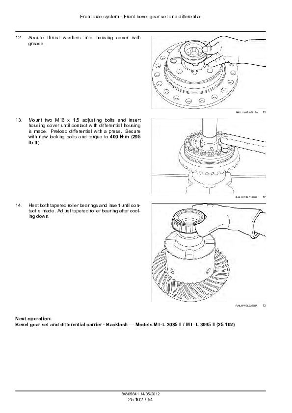
Front axle system - Front bevel gear set and differential
Limited slip differential - Assemble - DL-2400
721F
CAUTION: Burn hazard! Always wear heat-resistant protective gloves when handling heated parts. Failure to comply could result in minor or moderate injury.
Prior operation:
Limited slip differential - Disassemble — DL-2400 (25.102)
1. Mount two M16 x 1.5 locating pins (S) and press heated crown wheel onto differential housing until contact is made.
2. Insert thrust washer into differential housing.
3. Mount outer and inner discs in alternating order starting with an outer disk.
NOTE: The installation clearance of internal parts is corrected by mounting outer discs of different thicknesses.
NOTE: The difference in thickness between the left and right disc package must be less than 0.1 mm (0.004 in).
4. Install pressure ring.
5. Install axle bevel gear until contact is made. Then install inner discs with teeth.
6. Preassemble the differential spider and insert it into the differential housing/pressure ring.
7. Install second axle bevel gear.
8. Install second thrust ring into differential housing.
...


