John Deere 748H Skidder (S.N. —630435) Repair Service Manual (TM10288)
Catalog:
Model:
Complete Repair Service Technical Manual for John Deere 748H Skidder (S.N. —630435), with all the workshop information to maintain, repair, and rebuild like professional mechanics.
John Deere 748H Skidder (S.N. —630435) workshop technical manual (repair) includes:
* Numbered table of contents easy to use so that you can find the information you need fast.
* Detailed sub-steps expand on repair procedure information
* Numbered instructions guide you through every repair procedure step by step.
* Notes, cautions and warnings throughout each chapter pinpoint critical information.
* Bold figure number help you quickly match illustrations with instructions.
* Detailed illustrations, drawings and photos guide you through every procedure.
* Enlarged inset helps you identify and examine parts in detail.
TM10288 - John Deere 748H Skidder (S.N. —630435) Repair Technical Manual.pdf
tm10653 - John Deere Débardeurs 748H (SN —630435).pdf
tm10654 - John Deere Remolcador de troncos 748H ( —630435).pdf
tm11045 - John Deere скиддера 748H ( —630435).pdf
PRODUCT DETAILS:
Total Pages: 779 pages
File Format: PDF (bookmarked, ToC, Searchable, Printable)
Category: Repair
Language: English Spanish French Russian
Published on 2018/09/06
TABLE OF CONTENTS
Section 00: General Information...12
Group 0001: Safety Information...12
Recognize Safety Information...15
Follow Safety Instructions...16
Operate Only If Qualified...17
Wear Protective Equipment...18
Avoid Unauthorized Machine Modifications...19
Inspect Machine...20
Stay Clear of Moving Parts...21
Avoid High-Pressure Oils...22
Avoid High-Pressure Fluids...23
Do Not Use Starting Fluid...24
Beware of Exhaust Fumes...25
Prevent Fires...26
Prevent Battery Explosions...27
Handle Chemical Products Safely...28
Dispose of Waste Properly...29
Prepare for Emergencies...30
Use Steps and Handholds Correctly...31
Start Only From Operator's Seat...32
Use and Maintain Seat Belt...33
Prevent Unintended Machine Movement...34
Avoid Work Site Hazards...35
Operate Machine Safely...36
Keep Riders Off Machine...37
Avoid Backover Accidents...38
Avoid Machine Tip Over...39
Operating on Slopes...41
Operating or Traveling On Public Roads...42
Inspect and Maintain ROPS...43
Keep the Operator Protective Structure (OPS) in Place...44
Add and Operate Attachments Safely...45
Park and Prepare for Service Safely...46
Service Cooling System Safely...48
Remove Paint Before Welding or Heating...49
Make Welding Repairs Safely...50
Drive Metal Pins Safely...51
Group 0003: Torque Values...13
Hardware Torque Specifications...53
Keeping ROPS Installed Properly...54
Metric Bolt and Cap Screw Torque Values...56
Additional Metric Cap Screw Torque Values...58
Unified Inch Bolt and Cap Screw Torque Values...60
Check Oil Lines And Fittings...62
Service Recommendations for 37° Flare and 30° Cone Seat Connectors...63
Service Recommendations for O-Ring Boss Fittings...65
Service Recommendations For Flat Face O-Ring Seal Fittings...67
Service Recommendations for Metric Series Four Bolt Flange Fitting...69
Service Recommendations For Inch Series Four Bolt Flange Fittings...71
Section 01: Wheels...73
Group 0110: Powered Wheels and Fasteners...73
Wheel Remove and Install...76
Tire Remove and Install...78
Dual Wheel Installation...81
Section 02: Axles...82
Group 0200: Remove and Install...82
TeamMate™ IV Axles...84
Front Axle, Differential, and Oscillation Supports Remove and Install...85
Rear Axle and Differential Remove and Install...92
Front Axle Guards Remove and Install...98
Oscillation Supports Repair...99
Group 0225: Input Drive Shaft and U-Joints...82
Front Axle Drive Shaft Remove and Install...102
Rear Axle and Transmission Drive Shaft Remove and Install...104
Group 0260: Hydraulic System...82
Differential Lock Solenoid Valve Repair...111
Section 03: Transmission...114
Group 0300: Remove and Install...114
Transmission Remove and Install...129
Transmission Mount Remove and Install...143
Group 0315: Controls...114
Transmission Bump Shifter Remove and Install...147
Group 0325: Input Drive Shafts and U-Joints...114
Engine-to-Transmission Drive Shaft Remove and Install...153
Group 0350: Gears, Shafts, and Power Shift Clutches...114
Transmission Repair Procedures...158
Winch Drive Repair...159
Input Yoke Remove and Install...166
Group 0360: Hydraulic System...114
Transmission Charge Pump Remove and Install...174
Transmission Charge Pump Drive Repair...180
Transmission Suction Tube Repair...190
Transmission Control Valve Repair...192
Section 04: Engine...204
Group 0400: Removal and Installation...204
6068 John Deere Engine POWERTECH POWERTECH is a trademark of Deere & Company 6.8 L Diesel Engines—Base Engine—Use CTM104...204
6068 John Deere Engine POWERTECH POWERTECH is a trademark of Deere & Company 6.8 L—Level 14 Electronic Fuel System With Denso HPCR—Use CTM320 Repairs...204
Engine Removal...208
Engine Installation...219
Section 05: Engine Auxiliary Systems...223
Group 0505: Cold Weather Starting Aids...223
Do Not Use Ether Start Aid...225
Group 0510: Cooling System...223
Radiator Remove and Install...230
Transmission Cooler Remove and Install...234
Fan Guards Remove and Install...238
Belt Remove and Install...239
Belt Tensioner—Spring Tension Check...240
Belt Tensioner Remove and Install...242
Aftercooler Remove and Install...243
Hydraulic Oil Cooler Remove and Install...247
Fan Shroud Remove and Install...249
Group 0520: Intake System...223
Air Cleaner Remove and Install...253
Group 0530: Exhaust System...223
Muffler Remove and Install...256
Group 0560: External Fuel Supply System...223
Fuel Tank Remove and Install—Grapple Skidder...261
Section 07: Dampener Drive...265
Group 0752: Elements...265
Dampener Remove and Install...268
Transmission Cold Weather Disconnect Linkage Remove and Install...270
Transmission Cold Weather Disconnect Repair...274
Section 09: Steering System...280
Group 0930: Secondary Steering...280
Secondary Steering Pump Remove and Install...285
Group 0960: Hydraulic System...280
Steering Valve Remove and Install...295
Steering Valve Disassemble and Assemble...301
Steering Cylinder Remove and Install...308
Group 0962: Dual Mode Steering...280
Dual Mode Steering Solenoid Valve Remove and Install...314
Section 10: Service Brakes...317
Group 1015: Controls Linkage...317
Service Brake Pedal Remove and Install...319
Group 1060: Hydraulic System...317
Service Brake Valve Remove and Install...324
Service Brake Valve Disassemble and Assemble...328
Service Brake Accumulator Remove and Install...330
Section 11: Park Brake...334
Group 1111: Active Elements...334
Park Brake Remove and Install...339
Group 1160: Hydraulic System...334
Park Brake Solenoid Valve Repair...346
Section 17: Frame, Chassis, or Supporting Structures...349
Group 1740: Frame Installation...349
Welding Repair of Major Structure...352
Engine and Equipment Frames—Separate...354
Lower Pivot Pin Repair...359
Upper Pivot Pin Repair...366
Group 1746: Frame Bottom Guards...349
Engine Frame Bottom Guard Remove and Install...375
Equipment Frame Bottom Guard Remove and Install...377
Section 18: Operator's Station...379
Group 1800: Removal and Installation...379
Cab Remove and Install...399
Cab Isolators Remove and Install...417
Steering Column and Steering Wheel Remove and Install...420
Steering Column and Steering Wheel Disassemble and Assemble...423
Cab Tilt Hand Pump Remove and Install...425
Cab Tilt Hand Pump Disassemble and Assemble...428
Cab Tilt Hand Pump Bleeding Procedure...430
Cab Tilt Cylinder Remove and Install...433
Group 1810: Operator Enclosure...379
Window Remove and Install...440
Window Cleaning Procedure...444
Cab Door Remove and Install...445
Cab Door and Door Latch Disassemble and Assemble...447
Front Windshield Wiper Remove and Install...450
Rear Windshield Wiper Remove and Install...452
Windshield Wiper Adjustment...455
Group 1821: Seat and Seat Belt...379
Seat Remove and Install...459
Seat Disassemble and Assemble...461
Seat Belt Remove and Install...465
Group 1830: Heating and Air Conditioning...379
Proper Refrigerant Handling...467
Flush and Purge Air Conditioner System...468
R134a Refrigerant Oil Information...472
R134a Refrigerant Recovery, Recycling and Charging Station Installation Procedure...475
Recover R134a Refrigerant...477
Evacuate R134a System...478
Charge R134a System...480
Compressor Relief Valve Remove and Install...481
Refrigerant High/Low Pressure Switch Remove and Install...482
Air Conditioning Compressor Remove and Install...484
Air Conditioning Compressor Clutch Remove and Install...486
Air Conditioning Compressor Manifold Remove and Install...490
Air Conditioning Condenser Remove and Install...492
Evaporator Remove and Install...494
Expansion Valve Remove and Install...496
Blower Motor Remove and Install...498
Heater Core Remove and Install...500
Coolant Valve Remove and Install...502
Receiver Dryer Remove and Install...504
Freeze Control Switch Remove and Install...506
Section 19: Sheet Metal and Styling...509
Group 1910: Hood or Engine Enclosure...509
Hood Remove and Install...515
Section 20: Safety, Convenience, and Miscellaneous...520
Group 2003: Pressurized Water System...524
Pressurized Water System...524
Group 2004: Horn and Warning Devises...520
Horn Remove and Install...528
Reverse Warning Alarm Remove and Install...529
Section 21: Main Hydraulic System...530
Group 2160: Hydraulic System...530
Hydraulic Pump Remove and Install...539
Hydraulic Pump Disassemble and Assemble...547
Priority Valve Repair...562
Cold Start Dump Valve Remove and Install (If Equipped)...565
Fan Variable Speed and Reversing Manifold Remove and Install...567
Fan Variable Speed and Reversing Manifold Disassemble and Assemble...569
Hydraulic Fan Motor Remove and Install...570
Hydraulic Fan and Cooling Loop Pump Remove and Install...574
Hydraulic Reservoir Remove and Install...577
Hydraulic Oil Cleanup Procedure Using Portable Filter Caddy...586
Section 30: Winch...587
Group 3000: Removal and Installation...587
Winch 4000 Series Remove and Install...594
Fastening Cable to Winch Drum—4000 Series...600
Winch Free Spool Drag Adjustment...604
Winch 6000 Series Remove and Install...606
Fastening Cable to Winch Drum—6000 Series...611
Group 3015: Control Linkage...587
Winch Control Valve Linkage Remove and Install...615
Winch Control Cable Remove and Install...617
Group 3025: Input Drive Shafts and U-Joints...587
Winch Drive Shaft Remove and Install...624
Winch 4000 Series Drive Shaft Disassemble and Assemble...626
Group 3050: Drive and Clutch...587
Winch 4000 Series Drive and Clutch Repair...628
Winch 6000 Series Drive and Clutch Repair...629
Section 32: Stacking Blades...630
Group 3201: Blades...630
Stacking Blade Remove and Install...636
Spherical Bushing Remove and Install...641
Group 3215: Controls Linkage...630
Blade Control Linkage Remove and Install...645
Blade Control Valve Remove and Install...647
Group 3260: Hydraulic System...630
Blade Lift Cylinder Remove and Install...651
Section 38: Grapple...653
Group 3803: Grapple Mechanism...653
Grapple Remove and Install...658
Grapple Disassemble and Assemble...661
Grapple Damper Repair...663
Grapple Damper Adjustment...666
Dampener, Yoke, and Crosshead Pins Lubricate...669
Grapple Rotate Yoke Repair...671
Group 3815: Control Linkage...653
Single Lever Pilot Controller Remove and Install...692
Group 3840: Frames...653
Dual Function Grapple Cable Rollers Remove and Install...697
Dual Function Grapple Boom Remove and Install...699
Dual Function Grapple Arch Remove and Install...701
Group 3860: Hydraulic System...653
Boom or Arch Cylinder Remove and Install—Dual Function Grapple...706
Grapple Tong Cylinder Remove and Install...709
Grapple Rotate Motor Remove and Install...712
Grapple Rotate Motor Disassemble...715
Grapple Rotate Motor Assembly...723
Rotate Motor Drive Gear Remove and Install...732
Control Valve Options...733
Pilot Operated Control Valve Remove and Install...734
Dual Function Pilot Operated Control Valve Disassemble and Assemble...738
Control Valve Relief Valves Remove and Install...741
Lift Check Valve Disassemble and Assemble...743
Non-adjustable Circuit Relief Valve Disassemble and Assemble...744
Adjustable Circuit Relief Valve Disassemble and Assemble...746
Spool Valve Disassemble and Assemble...748
Detent Disassemble and Assemble...750
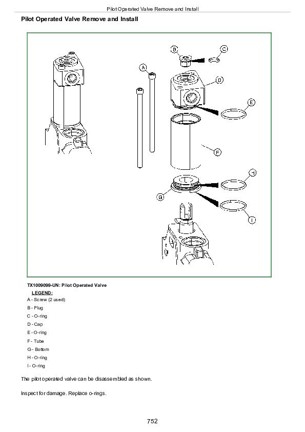
Pilot Operated Valve Remove and Install...752
Solenoid Operated Valve Remove and Install...754
Grapple Rotate Solenoid Valve Remove and Install...756
Grapple Rotate Solenoid Valve Disassemble and Assemble...759
Flow Divider Repair...761
Rotary Manifold Remove and Install...764
Rotary Manifold Disassemble and Assemble...767
Section 99: Dealer Fabricated Tools...771
Group 9900: Dealer Fabricated Tools...771
DFT1099 Bushing Drivers...774
DFRW20 Compressor Holding Fixture...776
John Deere 748H Skidder (S.N. —630435) Repair Service Manual (TM10288)


