John Deere 848H Skidder ( —630435) Diagnosis and Test Service Technical Manual (TM10287)
Catalog:
Model:
Complete Diagnosis & Tests Technical Manual with electrical wiring diagrams for John Deere 848H Skidder ( —630435) , with workshop information to maintain, diagnose, and rebuild like professional mechanics.
John Deere 848H Skidder ( —630435) workshop Diagnosis & Tests technical manual includes:
* Numbered table of contents easy to use so that you can find the information you need fast.
* Detailed sub-steps expand on repair procedure information
* Numbered instructions guide you through every repair procedure step by step.
* Troubleshooting and electrical service procedures are combined with detailed wiring diagrams for ease of use.
* Notes, cautions and warnings throughout each chapter pinpoint critical information.
* Bold figure number help you quickly match illustrations with instructions.
* Detailed illustrations, drawings and photos guide you through every procedure.
* Enlarged inset helps you identify and examine parts in detail.
TM10287 - John Deere 848H Skidder ( —630435) Technical Manual - Operation and Test.pdf
TM11046 - John Deere Débusqueurs 848H ( —630435).pdf
Category: Operation and Test
Language: English French
Published on 2018/09/06
PRODUCT DETAILS:
Total Pages: 1,175 pages
File Format: PDF (bookmarked, ToC, Searchable, Printable)
Language: English
TABLE OF CONTENTS
Section 9000: General Information....19
Group 01: Safety Information....19
Recognize Safety Information....22
Follow Safety Instructions....23
Operate Only If Qualified....24
Wear Protective Equipment....25
Avoid Unauthorized Machine Modifications....26
Inspect Machine....27
Stay Clear of Moving Parts....28
Avoid High-Pressure Oils....29
Avoid High-Pressure Fluids....30
Do Not Use Starting Fluid With Tier III Engine....31
Beware of Exhaust Fumes....32
Prevent Fires....33
Prevent Battery Explosions....34
Handle Chemical Products Safely....35
Dispose of Waste Properly....36
Prepare for Emergencies....37
Use Steps and Handholds Correctly....38
Start Only From Operator's Seat....39
Use and Maintain Seat Belt....40
Prevent Unintended Machine Movement....41
Avoid Work Site Hazards....42
Operate Machine Safely....43
Keep Riders Off Machine....44
Avoid Backover Accidents....45
Avoid Machine Tip Over....46
Operating on Slopes....48
Operating or Traveling On Public Roads....49
Inspect and Maintain ROPS....50
Keep the Operator Protective Structure (OPS) in Place....51
Add and Operate Attachments Safely....52
Park and Prepare for Service Safely....53
Service Cooling System Safely....55
Remove Paint Before Welding or Heating....56
Make Welding Repairs Safely....57
Service Tires Safely....58
Drive Metal Pins Safely....59
Section 9001: Diagnostic Trouble Codes (DTC)....60
Group 10: Engine Control Unit (ECU) Diagnostic Trouble Codes....64
Engine Control Unit (ECU) Diagnostic Trouble Codes....64
000091.03 - Throttle Voltage Out of Range High....60
000091.04 - Throttle Voltage Out of Range Low....60
000647.05 - Fan Proportional Solenoid Out of Range Low....60
000647.30 - Reversing Fan Switch Active Too Long....60
000676.03 - Glow Plug Relay Out of Range High....60
000676.05 - Glow Plug Relay Out of Range Low....60
001075.05 - Low Pressure Fuel Pump Out of Range Low....60
001075.06 - Low Pressure Fuel Pump Out of Range High....60
002003.09 - TCU Communication Data Error....60
002003.13 - TCU Communication Calibrate Error....60
002017.09 - SDM Communication Data Error....60
002017.13 - SDM Communication Calibrate Error....60
Group 20: Transmission Control Unit (TCU) Diagnostic Trouble Codes....97
Transmission Control Unit (TCU) Diagnostic Trouble Codes....97
000177.12 - Oil Temp Sensor Out of Range....60
000525.02 - Shift Parameter Erratic or Bad Data....60
000525.12 - Request for an Unidentified Shift Being Made....60
002000.09 - ECU Communication Data Error....60
002000.13 - ECU Communication Calibrate Error....60
298626.03 - Park and Not Park Active Out of Range High....60
298626.04 - Park and Not Park Active Out of Range Low....60
298678.04 - Clutch Valve Supply Voltage Out of Range Low....60
298808.31 - Output Speed Sensor Condition Exists....60
298809.31 - Starter Input Signal High....60
298811.05 - Solenoid B Out of Range Low....60
298811.06 - Solenoid B Out of Range High....60
298812.05 - Solenoid A Out of Range Low....60
298812.06 - Solenoid A Out of Range High....60
298814.05 - Solenoid 3 Out of Range Low....60
298814.06 - Solenoid 3 Out of Range High....60
298815.05 - Solenoid 2 Out of Range Low....61
298815.06 - Solenoid 2 Out of Range High....61
298818.31 - Directional Clutch Slip Condition Exists....61
298819.31 - Speed Clutch Slip Condition Exists....61
298907.31 - Not Park and Park Pressure Inputs Passive....61
298919.31 - Not Park and Park Pressure Inputs Active....61
298925.31 - Shifter Neutral and Reverse Inputs Active....61
298926.31 - Shifter Neutral and Forward Inputs Active....61
298927.31 - Neutral Forward Reverse Inputs Passive....61
298928.31 - Upshift and Downshift Inputs Active....61
298929.31 - Bottom of Clutch Input Passive....61
298931.31 - Output Speed Sensor Out of Range....61
298932.31 - Calibration Without Park Brake Applied....61
298933.31 - EEPROM Shift Parameter Condition....61
298934.03 - Solenoid Group 3 Out of Range High....61
298934.04 - Solenoid Group 3 Out of Range Low....61
298935.03 - Solenoid Group 2 Out of Range High....61
298935.04 - Solenoid Group 2 Out of Range Low....61
298936.03 - Solenoid Group 1 Out of Range High....61
298936.04 - Solenoid Group 1 Out of Range Low....61
298937.31 - Hold Clutch Pressure Condition....61
298939.31 - Calibrating Clutch Pressure Condition....61
298940.31 - Clutch D Fast Full Time Condition....61
298941.31 - Clutch C Fast Fill Time Condition....61
298942.31 - Clutch B Fast Fill Time Condition....61
298943.31 - Clutch A Fast Fill Time Condition....61
298944.31 - Clutch 4 Fast Fill Time Condition....61
298945.31 - Clutch 3 Fast Fill Time Condition....61
298946.31 - Clutch 2 Fast Fill Time Condition....61
298947.31 - Clutch 1 Fast Fill Time Condition....61
298948.31 - Cylinder Speed With Reverse Clutch Condition....61
298949.31 - Cylinder Speed With Forward Clutch Condition....61
298950.31 - Cylinder Speed Condition....61
298951.31 - Engine Speed Too Low For Calibration....62
298952.31 - Engine Speed Too High For Calibration....62
298953.31 - Sump Temp Too Low For Calibration....62
298954.05 - Solenoid 1 Out of Range Low....62
298954.06 - Solenoid 1 Out of Range High....62
298955.05 - Solenoid D Out of Range Low....62
298955.06 - Solenoid D Out of Range High....62
299359.31 - Forward and Reverse Inputs Active....62
523120.16 - Clutch Temperature Moderately High Value....62
523656.05 - Dual Mode Steer Output Out of Range Low....62
523656.06 - Dual Mode Steer Output Out of Range High....62
523689.04 - Differential Lock Short to Ground....62
523925.03 - Dual Mode Steer Switch Out of Range High....62
523925.04 - Dual Mode Steer Switch Out of Range Low....62
Group 30: Standard Display Monitor (SDM) Diagnostic Trouble Codes....235
Standard Display Monitor (SDM) Diagnostic Trouble Codes....235
000096.03 - Fuel Level Sensor Out of Range High....62
000096.04 - Fuel Level Sender Out of Range Low....62
000107.00 - Engine Air Filter Restriction Data Above Normal....62
000126.00 - Transmission Oil Filter Restriction Data Above Normal....62
000158.00 - System Voltage Data Above Normal....62
000158.01 - System Voltage Data Below Normal....62
000911.00 - Engine Air Filter Data Above Normal....62
001508.00 - Hydraulic Reservoir Oil Temperature Sensor Data Above Normal....62
001508.03 - Hydraulic Reservoir Oil Temperature Sensor Out of Range High....62
001508.04 - Hydraulic Reservoir Oil Temperature Sensor Out of Range Low....62
001508.16 - Hydraulic Oil Temp Sensor Moderately High Value....62
001713.00 - Hydraulic Oil Filter Restriction Data Above Normal....62
002000.09 - ECU Communication Data Error....62
002000.13 - ECU Communication Calibrate Error....62
002003.09 - TCU Communication Data Error....62
002003.13 - TCU Communication Calibrate Error....62
Section 9005: Operational Checkout....282
Group 10: Operational Checks....282
Complete Machine Operational Checkout....343
Section 9010: Engine....403
Group 05: Theory of Operation....403
Engine Fuel System Component Location....406
Engine Cooling System Component Location....408
Engine Fluid Sample Port Locations....409
Cold Weather Starting Aid....410
Group 15: Diagnostic Information....403
PowerTech Plus™ 4.5 L and 6.8 L (4045 and 6068) John Deere Engines....412
Engine Will Not Crank....403
Engine Coolant Temperature Above Normal....403
Engine Coolant Temperature Below Normal....403
Group 25: Tests....403
Fuel Line Leakage Test....420
Air Intake System Leakage Test....421
Air Filter Restriction Switch Test....424
Engine Slow and Fast Idle Speed Check....427
Section 9015: Electrical System....428
Group 05: System Information....428
Electrical Diagram Information....437
Group 10: System Diagrams....428
Fuse Specifications....444
System Functional Schematic, Wiring Diagrams and Component Locations Legend....446
System Functional Schematic and Section Legend....452
Cab Roof Harness (W9) Component Location....463
Cab Roof Harness (W9) Wiring Diagram....465
Load Center Harness (W10) Component Location....467
Load Center Harness (W10) Wiring Diagram....469
Engine Interface Harness (W11) Component Location....472
Engine Interface Harness (W11) Wiring Diagram....474
Engine Harness (W12) Component Location....476
Engine Harness (W12) Wiring Diagram....478
Transmission Harness (W13) Component Location....480
Transmission Harness (W13) Wiring Diagram....482
Hydraulic Reservoir Harness (W14) Component Location....483
Hydraulic Reservoir Harness (W14) Wiring Diagram....484
Fuel Sensor and Backup Alarm Harness (W15) Component Location....485
Fuel Sensor and Backup Alarm Harness (W15) Wiring Diagram....486
Radio Harness (W17) Component Location....487
Radio Harness (W17) Wiring Diagram....488
Secondary Steering Harness (W19) Component Location....489
Secondary Steering Harness (W19) Wiring Diagram....490
Grapple Rotate and Open/Close Harness (W24) Component Location—Pilot Control....492
Grapple Rotate and Open/Close Harness (W24) Wiring Diagram—Pilot Control....494
Grapple Rotate Harness (W25) Component Location—Mechanical Linkage....495
Group 15: Sub-System Diagnostics....428
Power and Charging Circuits Theory of Operation....500
Start and Park Circuits Theory of Operation....504
Engine Circuits (6.8 Liter Level 14 ECU) Theory of Operation....508
Standard Display Monitor Circuits Theory of Operation....514
Transmission Control Unit (TCU) Theory of Operation....520
Differential Lock Circuits Theory of Operation....525
Transmission Lock-Up Circuits Theory of Operation....526
Grapple Pilot Control Circuits Theory of Operation....527
Secondary Steering Circuits Theory of Operation....528
Dual Mode Steer Circuits Theory of Operation....529
Fan Reverse and Horn Circuits Theory of Operation....530
Windshield Washer and Wiper Circuits Theory of Operation....531
A/C and Precleaner Circuits Theory of Operation....532
Heater and Blower Circuits Theory of Operation....533
Work Lights Circuits Theory of Operation....534
Deluxe Work Lights Circuits Theory of Operation....535
Air Seat and Dome Light Circuits Theory of Operation....536
Group 16: Monitor Operation....429
Standard Display Monitor (SDM) Operation....541
Standard Display Monitor (SDM) Menu Structure—Service Mode....568
Standard Display Monitor (SDM)—Temperature Format....549
Standard Display Monitor (SDM)—Change Units....572
Standard Display Monitor (SDM)—Hide—Unhide Main Menu....552
Group 20: References....429
Battery Specifications....555
Diagnose Battery Malfunctions....556
Check Battery Electrolyte Level and Terminals....557
Service ADVISOR™ Diagnostic Application....560
Reading Diagnostic Trouble Codes with Service ADVISOR™ Diagnostic Application....561
Service ADVISOR™ Connection Procedure....562
Intermittent Diagnostic Trouble Code (DTC) Diagnostics....565
Programming Standard Display Monitor Temperature Format....566
Standard Display Monitor (SDM) Menu Structure—Service Mode....568
Standard Display Monitor (SDM)—Change Units....572
Standard Display Monitor (SDM)—Hide/Unhide Main Menu....573
Historical Diagnostic Trouble Code Retrieval....575
Diagnostic Trouble Codes (DTC) Quick Reference List....577
Diagnostic Trouble Codes (DTC)—General Information....588
Calibration of Transmission Control Unit (TCU)....589
Transmission Diagnostic Trouble Codes—Limp Home Mode....593
Troubleshooting Transmission Gear Solenoid Diagnostic Trouble Codes....594
Program Controller....596
CAN Circuit Test....597
Secondary Steering Controller Bench Test....601
Standard Display Monitor (SDM) Test....602
Two-Wire Sensor Circuit Check Using Monitor Display Unit or SERVICE ADVISOR SERVICE ADVISOR is a trademark of Deere & Company....430
Three-Wire Sensor Circuit Check Using Monitor Display Unit or SERVICE ADVISOR SERVICE ADVISOR is a trademark of Deere & Company....430
Electrical Component Specification....606
Relay Test....609
Diode Test....611
Diode Module Test....612
Remove and Install Transmission Control Unit (TCU)....614
Remove and Install Engine Control Unit (ECU)....616
Remove and Install Single Lever Pilot Control Relays....617
Connector Terminal Test....618
Replace DEUTSCH DEUTSCH is a trademark of Deutsch Co. Rectangular or Triangular Connectors....430
Replace DEUTSCH DEUTSCH is a trademark of the Deutsch Co. Connectors....430
Install DEUTSCH DEUTSCH is a trademark of the Deutsch Co. Contact....430
Replace WEATHER PACK WEATHER PACK is a trademark of Packard Electric. Connector....430
Replace SURE-SEAL SURE-SEAL is a trademark of ITT Cannon Electric. Connector with WEATHER PACK WEATHER PACK is a trademark of Packard Electric. Connector....430
Install WEATHER PACK WEATHER PACK is a trademark of Packard Electric. Contact....430
Remove Connector Body from Blade Terminals....633
Crimper Tool For Transmission Control Unit Connector—Operation....634
Crimper Tool For Transmission Control Unit Connector—Remove And Install Die Set....635
Crimper Tool For Transmission Control Unit Connector—Contact Support Adjustment....637
Crimper Tool For Transmission Control Unit Connector—Crimping Procedure....638
Crimper Tool For Transmission Control Unit Connector—Crimp Height Inspection....641
Crimper Tool For Transmission Control Unit Connector—Crimp Height Adjustment....642
Replace Transmission Control Unit Connector Terminals....644
Cinch CP Connector Assemble....646
Cinch CP Connector Terminal Removal....653
Cinch CP Connector Terminal Hand Crimp Process....656
Section 9020: Power Train....660
Group 05: Theory of Operation....660
Power Train Component Overview....664
DF180 Series Powershift Transmission....665
TeamMate Axles....666
Transmission Operation....667
Transmission Component Identification....668
Transmission Diagram....670
Lockup Torque Converter Operation....672
Transmission Hydraulic System Operation....843
Transmission Charge Pump Operation....677
Transmission Filter Bypass Valve Operation....679
Transmission Control Valve Port Identification....681
Transmission Proportional Solenoid Valves Identification....683
Transmission Control Valve Operation....685
Control Valve-to-Front Housing Oil Passage Identification....687
Transmission Pressure Regulator Valve Operation....688
Park Brake and Differential Lock Control Valve....690
Park Brake Control Circuit....692
Park Brake Manual Release Operation....697
Differential Lock Control Circuit....699
Group 15: Diagnostic Information....660
Transmission Overfills With Oil....660
Transmission Clutch Slippage....660
Transmission Shifts Too Slow....660
Transmission Shifts Too Fast....660
Park Brake Activates When Service Brakes Are Applied (No Load on Engine While in Gear)....660
Machine Will Not Move (Load on Engine or Engine Stalls When Shifted Into Gear)....660
Machine Creeps in Neutral (Load Put on Engine When Service Brakes Are Applied)....660
Transmission System Overheats....660
Lube Pressure Low, Transmission Charge Pressure Normal....660
Excessive Transmission Noise Under Load or No Load....660
Machine Makes Excessive Transmission Noise When Moving....660
Erratic Transmission Oil Pressure....661
Excessive Transmission Oil Pressure....661
Low Transmission Oil Pressure in All Gears....661
Low Transmission Oil Pressure in One Gear but Correct in Other Gears....661
Transmission Breather Oil Leakage....661
Filter or Filter Oil Lines Blow Out....661
Low Lube Pressure (Not All Gears)....661
Excessive Lube Pressure (Not All Gears)....661
Low Transmission Oil Cooler Inlet Pressure, Correct Lube Pressure....661
Low Transmission Oil Cooler Inlet Pressure and Lube Pressure....661
Machine Lacks Power....661
Excessive Torque Converter Noise (Under Load or No Load)....661
Torque Converter Stall, RPM Too Low....661
Torque Converter Stall, RPM Too High....661
Machine Will Not Move in Any Gear and Park Brake Indicator Is On....661
Excessive Machine Vibration....661
Excessive Driveline Vibration....661
Park Brake Comes On While Using a Hydraulic Function....661
Park Brake Engages While Machine Is Moving....661
Park Brake Will Not Release....661
No Differential Lock Operation....661
Differential Lock Slippage....661
Excessive Differential or Axle Noise....661
Oil Seepage from Outer Axle Seal....661
Power Train Component Location....790
Group 20: Adjustments....661
Park Brake Manual Release Procedure....797
Group 25: Tests....661
Transmission Oil Warm-Up Procedure....803
Transmission Pump Flow Test....804
Transmission System Pressure Test....807
Transmission Lube Circuit Pressure Test....809
Transmission Control Circuit Pressure Test....811
Converter-In Pressure Test....814
Converter-Out Pressure Test....816
Torque Converter Pressure Relief Test....818
Converter-Out Flow Test....822
Lockup Torque Converter Clutch Pressure Test....825
Torque Converter Stall Speed Test....827
Park Brake Pressure Test....829
Differential Lock Pressure Test....833
Section 9025: Hydraulic System....838
Group 05: Theory of Operation....838
Hydraulic System Operation....843
Main Pump and Reservoir Hydraulic Circuit Operation....844
Cooling Loop and Reversing Fan Circuit Operation....846
Service Brake Hydraulic Circuit Operation....848
Steering and Secondary Steering Hydraulic Circuit Operation....850
Dual Mode Steering Hydraulic Circuit Operation....852
Pilot Control Hydraulic Circuit Operation....855
Grapple Rotate Hydraulic Circuit Operation....858
Main Hydraulic Pump and Pressure Compensator Operation....859
Brake Accumulator Operation....862
Hydraulic Reservoir Operation....863
Hydraulic Oil Return Filter Operation....865
Hydraulic Fan Filter Operation....867
Brake Valve Operation....868
Priority Valve Operation....871
Steering Valve and System Operation....875
Secondary Steering Inlet Manifold Operation....877
120 Series Cylinder Operation....879
Blade Manually Operated Valve Section Operation....881
Arch and Boom Pilot Operated Valve Section Operation....883
System Relief Valve Operation....884
Circuit Relief Valve—Adjustable with Anticavitation Operation....886
Circuit Relief Valve—Non-Adjustable Operation....888
Grapple Tong Flow Divider Operation....889
Pilot Controller Operation....891
Grapple Rotate Solenoid Valve Operation....892
Dual Mode Steering Solenoid Valve Operation....894
Rotary Manifold Operation....896
Fan Pump Operation....897
Fan Variable Speed and Reversing Manifold Operation....900
Reversing Fan Motor Operation....902
Hydraulic Oil Cooler Operation....903
Cab Tilt Circuit Operation....904
Group 15: Diagnostic Information....839
Hydraulic System Overheating....839
Hydraulic Function Drifts Down....839
No Steering or Hydraulic Functions....839
Hydraulic Functions Slow....839
Individual Functions Slow (Cycle Time Slow)....839
No Hydraulic Functions (Steering Normal)....839
Low Hydraulic Power (Pressure)....839
Excessive Hydraulic Pump Noise....839
Function Powers Up or Down Without Moving Lever....839
Grapple Rotate Stalls....839
Grapple Rotates Too Fast....839
Grapple Rotates Slow....839
Tongs Do Not Close Evenly....839
Tongs Open or Close Slowly....839
Grapple Loses Logs During Skidding....839
Transmission Overfills With Oil....839
No Steering (Hydraulic Functions Normal)....839
Steering Valve Does Not Center....839
Steering Valve Locks Up....839
Frames Turn Wrong Direction....839
Steering Slow or Hard....839
Steering Erratic or Spongy....839
Machine Wanders....839
Quick Steer Mode Not Engaging....839
Quick Steer Mode Not Disengaging....839
Quick Steer Mode Engaging When Disengaged....839
Poor or No Brakes (Other Hydraulic Systems Normal)....839
Brakes Overly Aggressive....839
Brakes Drag....839
Brakes Chatter or Noisy....839
Delay in Braking....840
Fan Does Not Reach Full Speed (Both Directions)....840
Fan Does Not Reach Full Speed (Forward Direction Only)....840
Fan Does Not Reach Full Speed (Reverse Direction Only)....840
Fan Does Not Spin (Both Directions)....840
Fan Does Not Slow Down Before Reversing....840
High Cooler Pressure or Pressure Spikes....840
High Return Pressure at Fan Reversing Manifold Port T....840
High Flow From Fan Motor Case Drain....840
Fan Pump is Cavitating....840
Hydraulic System Component Location Cable Skidder Manual with Lock Up Torque Converter....983
Hydraulic System Component Location Grapple Skidder Dual Function Pilot with Lock Up Torque Converter....985
Hydraulic System Schematic....987
Group 20: Adjustments....840
Service Brake Pedal Adjustment....992
Service Brake Inspection and Adjustment....993
Service Brake Bleeding Procedure....994
Grapple Damper Adjustment....998
Group 25: Tests....840
D15032NU Vacuum Pump Installation....1002
JT02156A Digital Pressure and Temperature Analyzer Installation....1003
JT07148 Digital Hydraulic Tester....1005
Hydraulic Oil Warm-Up Procedure....1006
Main Hydraulic Pump Identification....1007
Main Hydraulic Pump Standby Pressure Test....1008
Main Hydraulic Pump Flow Test....1011
Main Hydraulic Pump Leakage Test....1014
Pressure Reducing Valve Pressure Test....1017
Pilot Controller Pressure Test....1019
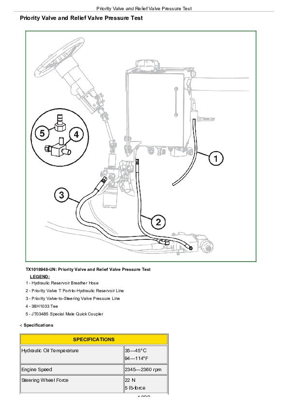
Priority Valve and Relief Valve Pressure Test....1022
Priority Valve "LS" Port Flow Test....1025
Priority Valve and Relief Valve Leakage Test....1027
System and Circuit Relief Valve Pressure Test....1029
Hydraulic Component Leakage Test....1034
Cylinder Leakage Test....1038
Cylinder Drift Test....1040
Dual Mode Steering Engagement Pressure Test....1042
Grapple Rotate Motor Crossover Relief Valve Pressure Test....1045
Grapple Rotate Solenoid Valve Neutral Leakage Test....1047
Grapple Tong Flow Divider Relief Valve Test....1049
Rotary Manifold Center Seal Leakage Test....1051
Rotary Manifold Drain and Lower Seal Leakage Test....1053
Service Brake Valve and Accumulator Pressure Test....1055
Service Brake Valve Leakage Test....1058
Steering Valve Neutral Leakage Test....1061
Hydraulic Functions Cycle Time Test....1063
Hydraulic Oil Filter Inspection Procedure....1065
Cooling Fan Circuit Test Procedure....1066
Fan Motor Case Drain Test....1071
Secondary Steering Operation Test....1073
Section 9030: Winch....1076
Group 05: Theory of Operation....1076
John Deere 4000 and 6000 Winches....1078
Group 15: Diagnostic Information....1076
Winch Control Lever Effort Excessive....1076
Winch Clutch Slips....1076
Winch Free Spool Effort Excessive....1076
Winch Brake Will Not Hold....1076
Winch Will Not Free Spool....1076
Transmission Oil Level Varies Excessively....1076
Winch Makes Grinding Noise When Going from FREE SPOOL to BRAKE OFF....1076
Winch Component Location....1094
Winch Hydraulic Schematic....1095
Group 20: Adjustments....1076
Winch Control Cable Adjustment Check....1097
Brake Off Adjustment—4000 Series Winch....1098
Brake Off Adjustment—6000 Series Winch....1103
Group 25: Tests....1076
Winch System Pressure Test....1112
Winch Leakage Test....1117
Winch Drum Rolling Drag Test....1121
Section 9031: Heating and Air Conditioning....1123
Group 05: Theory Of Operation....1123
Air Conditioning System Cycle Of Operation....1126
Group 15: Diagnostic Information....1123
Diagnose Air Conditioning System Malfunctions....1123
Diagnose Heater System Malfunctions....1123
Air Conditioning System Component Location....1153
Group 25: Tests....1123
Air Conditioning System Checks....1158
R134a Air Conditioning System Test....1161
Air Conditioner Freeze Control Switch Test....1165
Air Conditioning Compressor Clutch Test....1167
Air Conditioning High/Low Pressure Switch Test....1168
Air Conditioning Expansion Valve Test....1170
Refrigerant Leak Test....1173
John Deere 848H Skidder ( —630435) Diagnosis and Test Service Technical Manual (TM10287)


