John Deere 8R Tractors Repair (S. N. 120000—) 8225R, 8245R, 8270R, 8295R, 8320R, 8335R, 8345R, 8370R, 8400R Tractors Repair Service Manual (TM146319)
Catalog:
Model:
Complete Repair Service Technical Manual for John Deere 8R Tractors Repair (S. N. 120000—) 8225R, 8245R, 8270R, 8295R, 8320R, 8335R, 8345R, 8370R, 8400R Tractors, with all the workshop information to maintain, repair, and rebuild like professional mechanics.
John Deere 8R Tractors Repair (S. N. 120000—) 8225R, 8245R, 8270R, 8295R, 8320R, 8335R, 8345R, 8370R, 8400R Tractors workshop technical manual (repair) includes:
* Numbered table of contents easy to use so that you can find the information you need fast.
* Detailed sub-steps expand on repair procedure information
* Numbered instructions guide you through every repair procedure step by step.
* Notes, cautions and warnings throughout each chapter pinpoint critical information.
* Bold figure number help you quickly match illustrations with instructions.
* Detailed illustrations, drawings and photos guide you through every procedure.
* Enlarged inset helps you identify and examine parts in detail.
TM146319 - John Deere 8R Tractors Repair (S. N. 120000—) 8225R, 8245R, 8270R, 8295R, 8320R, 8335R, 8345R, 8370R, 8400R Tractors Technical Manual - Repair.pdf
tm146328 - Remise en état des tracteurs 8R (N° de série 120000—)
tm146329 - Reparatur der Traktoren 8R (Seriennummern 120000—)
tm146339 - Riparazione trattori 8R (N. S. 120000—)
tm146354 - Reparação de Tratores 8R (Número de Série 120000 —)
tm146359 - Устранение неисправностей тракторов серии 8RT (серийные номера 120000–)
PRODUCT DETAILS:
Total Pages: 3,104 pages
File Format: PDF (bookmarked, ToC, Searchable, Printable)
Category: Repair
Language: English French German Italian Portuguese Russian
Published on 2019/08/26
TABLE OF CONTENTS
Section 10: General Information................39
Group 05A: Safety................39
Recognize Safety Information................43
Understand Signal Words................44
Follow Safety Instructions................45
Prevent Machine Runaway................46
Avoid Backover Accidents................47
Handle Fluids Safely—Avoid Fires................48
Prevent Battery Explosions................49
Prepare for Emergencies................50
Handling Batteries Safely................51
Handle Agricultural Chemicals Safely................53
Park Machine Safely................55
Support Machine Properly................56
Wear Protective Clothing................57
Work in Clean Area................58
Clean Vehicle of Hazardous Pesticides................59
Service Machines Safely................60
Stay Clear of Rotating Drivelines................61
Work In Ventilated Area................62
Illuminate Work Area Safely................63
Replace Safety Signs................64
Use Proper Lifting Equipment................65
Wait Before Opening High-Pressure Fuel System................66
Service Accumulator Systems Safely................67
Protect Against High Pressure Spray................68
Service Cooling System Safely................69
Avoid High-Pressure Fluids................70
Remove Paint Before Welding or Heating................71
Avoid Heating Near Pressurized Fluid Lines................72
Handle Starting Fluid Safely................73
In Case of Fire................74
Avoid Static Electricity Risk When Refueling................75
Avoid Hot Exhaust................77
Clean Exhaust Filter Safely................78
Prevent Acid Burns................81
Keep ROPS Installed Properly................83
Instructional Seat................84
Use Steps and Handholds Correctly................85
Service Front-Wheel Drive Tractor Safely................86
Transport Tractor Safely................87
Follow Tire Recommendations................88
Service Tires Safely................89
Avoid Harmful Asbestos Dust................90
Practice Safe Maintenance................91
Use Proper Tools................93
Construct Dealer-Made Tools Safely................94
Decommissioning — Proper Recycling and Disposal of Fluids and Components................95
Install All Guards................96
Live With Safety................97
Group 05B: General References................40
List of References................3008
Trademarks................102
Sealants and Adhesives Cross-Reference Chart................105
Metric Bolt and Screw Torque Values................108
Unified Inch Bolt and Screw Torque Values................110
Face Seal Fittings Assembly and Installation—All Pressure Applications................112
Metric Face Seal And O-ring Stud End Fitting Torque Chart—Standard Pressures................113
Metric Face Seal and O-ring Stud End Fitting Torque Chart—High Pressure Applications................115
SAE Face Seal and O-ring Stud End Fitting Torque Chart—Standard Pressures................117
SAE Face Seal and O-ring Stud End Fitting Torque Chart—High Pressure Applications................119
Four Bolt Flange Fittings Assembly and Installation—All Pressure Applications................121
SAE Four Bolt Flange Cap Screw Torque Values—Standard Pressure Applications................122
SAE Four Bolt Flange Cap Screw Torque Values—High Pressure Applications................123
External Hexagon Port Plug Torque Chart................124
Prevent Hydraulic System Contamination................126
Check Oil Lines and Fittings................127
Basic Electrical Component Handling / Precautions For Vehicles Equipped With Computer Controlled Systems................128
Identify Zinc-Flake Coated Fasteners................129
Use Torque Wrench Adapter................130
Servicing and Connecting Snap to Connect STC™ Fittings................132
Use Special Wrench................134
Install Hydraulic Fittings................135
Glossary of Terms................137
Aftertreatment Indicators Overview................142
Changing Diesel Exhaust Fluid (DEF) Dosing Unit Filter................146
Cleaning Diesel Exhaust Fluid (DEF) Tank................148
Section 20: Engine................150
Group 00: Component Removal and Installation................150
List of References................3008
Essential, Recommended, and Fabricated Tools 20—00................153
Other Material 20—00................154
Specifications 20—00................155
Remove Engine................156
Install Engine................165
Remove Front Frame................174
Install Front Frame................175
Group 05: Engine Repair................150
List of References................3008
Essential, Recommended, and Fabricated Tools 20—05................183
Other Material 20—05................184
Specifications 20—05................185
Replace Torsional Damper................186
Engine Repair—Use CTM................190
Remove and Install Timing Gear Cover................191
Section 30: Fuel, Air Intake, Exhaust, and Cooling................195
Group 05: Diesel Fuel System................195
List of References................3008
Specifications 30—05................199
Remove and Install Fuel Tank................200
Replace Fuel Filter, Electric Fuel Pump, and Bleed Fuel System................208
Group 10: Air Intake System................195
List of References................3008
Specifications 30—10................211
Air Intake Pipe Connections................212
Remove and Install Air Cleaner Pipe................215
Remove and Install Aspirator Pipe................218
Remove and Install Charge Air Cooler Pipes................221
Group 15: Auxiliary Drive System................195
List of References................3008
Essential, Recommended, and Fabricated Tools 30—15................235
Specifications 30—15................236
Auxiliary Drive Belt Routing................237
Belt Tensioner Location................238
Inspect Belt Tensioner................239
Replace Idler Pulleys and Belt Tensioner................242
Remove and Install Vari-Cool™ Fan Belt................243
Replace Auxiliary Drive Pulley................249
Replace Auxiliary Driveshaft Seal................254
Group 20: Radiator and Coolers................195
List of References................3008
Essential, Recommended, and Fabricated Tools 30—20................258
Other Material 30—20................259
Specifications 30—20................260
Draining, Flushing, and Refilling Cooling System................262
Test Radiator and Deaeration Tank................270
Test Radiator Cap................271
Remove and Install Radiator................272
Check and Fill Vari-Cool™ Fan Sheaves................278
Remove and Install Vari-Cool™ Drive Assembly................280
Remove and Install Vari-Cool™ Fan Driven Assembly................282
Repair Vari-Cool™ Fan Drive Assembly................285
Repair Vari-Cool™ Fan Driven Assembly................314
Remove and Install Vari-Cool™ Control Valve................329
Repair Vari-Cool™ Control Valve................330
Remove and Install Air Conditioning Condenser................331
Remove and Install Fuel Cooler—Hydraulic Oil Cooler................333
Leak Test Hydraulic Oil Cooler................334
Group 25: Exhaust System................196
List of References................3008
Specifications 30—25................337
Service Exhaust System................341
Replace NOx Sensor................396
Remove and Install DEF Tank................403
Replace Header Assembly................411
Replace DEF Dosing Unit................413
Replace DEF Dosing Injector................417
Section 40: Electrical................419
Group 05: Connectors................419
List of References................3008
Essential, Recommended, and Fabricated Tools 40—05................428
Other Material 40—05................430
Use Electrical Insulating Compound................431
Using High-Pressure Washers................432
Installation of Repair Wire Assembly (RWA)................433
Repair AMP™ Connector................442
Repair AMPSEAL 16™ Connectors................444
Bosch™ Connectors................449
Remove Connector Body from Blade Terminals................452
CINCH™ Control Unit Connectors................453
Exploded View—CINCH™ FlexBox Connectors................462
CINCH™ FlexBox Connectors................462
Repair CPC™ Blade Type Connectors................466
Repair CPC™, Large Mate-N-Loc™, and Metrimate™ Pin Type Connectors................467
Repair DEUTSCH™ Connectors................469
Repair DEUTSCH™ Implement Connectors................473
Repair ITT Connector................476
Repair Small Mate-N-Loc™ Socket Connector................480
Repair Small Mate-N-Loc™ Pin Connector................481
Repair (Push Type) Metri-Pack™ Connectors................482
Repair Molex™ Control Unit Connectors................485
Repair Molex™ Connector................492
Repair SUMITOMO™ Connectors................495
Repair Tyco™ Fuel Injector Connector................498
Repair WEATHER PACK™ Connector................500
Repair YAZAKI™ Connectors................503
Group 10: Charging Circuit................419
List of References................3008
Specifications 40—10................508
Repair Alternator—Use CTM................509
Replace Alternator................510
Replace Alternator and Battery Fuse................512
Group 15: Starting Circuit................420
List of References................3008
Essential, Recommended, and Fabricated Tools 40—15................516
Specifications 40—15................517
Repair Starter—Use CTM................518
Remove and Install Starter Motor................519
Replace Starter Circuit Relay................520
Replace Master Fuse................523
Group 20: Relays, Fuses, Solenoids, and Switches................420
List of References................3008
Essential, Recommended, and Fabricated Tools 40—20................529
Specifications 40—20................530
General Repair Procedures 40—20................533
Replace Hydraulic Backup Pump Fuse................534
Replace Hydraulic Backup Pump Relay................536
Replace Starting Aid Solenoid................538
Replace Sensors e23™ Transmission................539
Replace Solenoids e23™ Transmission................541
Replace Park Supply Solenoid (e23™)................543
Replace Park Sump Block Solenoid (e23™)................544
Replace MFWD Solenoid (e23™)................545
Replace Range Clutch R1 and R2 Solenoids (e23™)................546
Replace Oil Cooler Bypass Solenoid (e23™)................547
Replace Lube Prioritization Valve Solenoid (e23™)................548
Replace Sensors and Solenoids PST Transmission................549
Replace Electrohydraulic Shift Valve Solenoids (PST)................550
Replace Park Brake Release Solenoid (PST)................551
Replace MFWD Solenoid (PST)................552
Replace Sensors IVT™ Transmission................553
Replace Solenoids IVT™ Transmission................555
Replace Clutch Enable Solenoid (IVT™)................556
Replace MFWD Solenoid (IVT™)................557
Replace Park Supply Solenoid................558
Replace Park Sump Block Solenoid (IVT™)................559
Replace Hydro Clutch Unit Solenoid (IVT™)................560
Replace Ring Unit Hydro Control Solenoid (IVT™)................561
Replace Loop Flush Cut Off Solenoid (IVT™)................562
Replace PTO Solenoid................563
Replace Differential Lock Solenoid................564
Replace Engine Oil Pressure Switch................565
Replace Differential Lock Switch................566
Replace Cab Door Light Switch................568
Replace Starting Aid Switch................569
Replace Ignition Switch................573
Replace Key Immobilizer................577
Replace Seat Raise-Lower Switch................581
Replace Seat Firmness Switch—ActiveSeat™................583
Replace Heated Seat Switch................585
Replace Operator Presence Seat Switch................587
Replace Hydraulic Oil Filter Restriction Switch................589
Replace Ethernet Switch................590
Replace Battery Disconnect Switch................591
Replace External Hitch Raise-Lower Switches................593
Replace Air Conditioning Dual Pressure Sensor................595
Replace Air Conditioning Temperature Sensor................596
Replace Air Conditioning Motor Speed Control................597
Replace External PTO Switch................598
Group 25: Monitoring System................421
List of References................3008
Specifications 40—25................605
Other Material 40—25................607
General Information 40—25................608
Disconnect Electrical Circuit................609
Control Units Identification................610
Replace Control Units................612
Replace Navigation Bar................614
Replace Engine Coolant Temperature Sensor................615
Replace Engine Coolant Level Sensor................616
Replace Engine Coolant Loss Sensor................617
Replace Engine Crank Speed Sensor................618
Replace Fuel Level Sensor................619
Replace Foot Throttle Sensor................622
Replace Wheel Angle Sensor................623
Replace Wheel Angle Sensor—ILS™................628
Replace Steering Column Module................633
Replace Steering Input Device................636
Replace Primary Transmission Speed Sensor................640
Replace Secondary Transmission Speed Sensor................641
Replace PTO Speed Sensor................642
Replace Radar Sensor................644
Replace Hydraulic Charge Pump Pressure Sensor................645
Replace Hydraulic Oil Temperature Sensor................646
Replace INDEPENDENT LINK SUSPENSION™ Cylinder Position Sensor (Early Version)................647
Replace INDEPENDENT LINK SUSPENSION™ Cylinder Position Sensor (Late Version)................651
Replace Hitch Position Sensor................657
Replace Draft Sensing Sensor................659
Replace Gyroscope Sensor................661
Replace CommandCenter™ Processor................663
Replace Hydraulic Oil Level Presence Sensor................666
Group 30: CommandARM™................422
List of References................3008
Specifications 40—30................669
Armrest Test Procedures................670
Remove and Install CommandARM™ Assembly................671
Replace Armrest Interface Control Unit (AIC)................672
Replace Throttle Control Module................674
Replace Transmission Lever Control Module................675
Replace SCV Control Lever Module................676
Replace Rear Hitch Control Lever and SCV I Control Lever Module................677
Replace Hitch Controls Module................678
Replace Rear PTO Switch................680
Replace Front PTO Switch................681
Replace Secondary Brake Switch................682
Replace Cab Controls Module................683
Replace SCV Lock Module................684
Replace Joystick Module................685
Group 35: Implement and Accessory Connectors................423
List of References................3008
Specifications 40—35................689
Replace Seven-Terminal Outlet Socket................690
Replace GreenStar™ Terminal Connector................692
Replace Auxiliary Power Strip................693
Replace Three-Pin Accessory Outlet................695
Replace Three-Pin Accessory Outlet—Storage Box................696
Replace and Adjust Field Lights................697
Group 40: Convenience and Accessory................423
List of References................3008
Specifications 40—40................700
Replace Wiper Motor................701
Replace Windshield Washer Pumps................704
Replace Circulation Blower Motor................706
Replace HVAC Pressurizer Blower Motor................709
Replace Air Flow Mode Motor................712
Remove Radio and Speakers................716
Replace Refrigerator................719
Replace Refrigerator Tray................720
Replace Refrigerator Top Cover................721
Replace Refrigerator Door................723
Replace Refrigerator Thermostat................724
Replace Refrigerator Module................729
Section 50A: Infinitely Variable Transmission (IVT™)................734
Group 00: Component Removal and Installation................734
List of References................3008
Essential, Recommended, and Fabricated Tools 50A—00................739
Other Material 50A—00................740
Specifications 50A—00................741
Remove Transmission—IVT™................742
Install Transmission—IVT™................762
Remove and Install Scavenge Pump—IVT™................980
Group 05: In Tractor Repair................734
List of References................3008
Essential, Recommended, and Fabricated Tools 50A—05................785
Other Material 50A—05................786
Specifications 50A—05................787
Replace Input Shaft Front Seal—IVT™................788
Replace Auxiliary Driveshaft Seal—IVT™................791
Synchronizer/Shift Assembly Repair—In Chassis—IVT™................794
Service Hydrostatic Jumper Tubes—IVT™................806
Group 10: Transmission Repair................734
List of References................3008
Essential, Recommended, and Fabricated Tools 50A—10................813
Other Material 50A—10................815
Specifications 50A—10................816
General Repair Procedures 50A—10................818
Hydrostatic Module Replacement—IVT™................821
Install Transmission Onto Repair Stand—IVT™................823
Disassemble Transmission—IVT™................824
Exploded View—Valve Manifold—IVT™................841
Repair Valve Manifold—IVT™................843
Repair Synchronizer—IVT™................844
Cross Sectional View—C1-C2 Shift Assembly—IVT™................849
Repair C1-C2 Shift Assembly—IVT™................850
Repair Accumulator—IVT™................855
Exploded View—Hydrostatic Module Assembly—IVT™................857
Multi-Function Valves—IVT™................858
Test Multi-Function Valves—IVT™................859
Hydrostatic Module Loop Flush Valve—IVT™................860
Repair Hydrostatic Module Assembly—IVT™................863
Exploded View—Reverse Brake—IVT™................867
Repair Reverse Brake Housing—IVT™................869
Cross Sectional View—High-Low Clutch Assembly—IVT™................872
Repair High-Low Clutch Assembly—IVT™................873
Cross Sectional View—Planetary Input Assembly—IVT™................883
Repair Planetary Input—IVT™................885
Exploded View—Planetary Assembly—IVT™................887
Repair Planetary Assembly—IVT™................889
Cross Sectional View—Park Brake—IVT™................902
Repair Park Brake—IVT™................903
Cross Sectional View—MFWD/ILS™ Clutch—IVT™................907
Repair MFWD/ILS™ Clutch—IVT™................908
Repair Output Housing-to-MFWD—IVT™................916
Repair Output Housing-to-ILS™—IVT™................919
Repair Scavenge Pump—IVT™................921
Group 15: Assemble Transmission................735
List of References................3008
Essential, Recommended, and Dealer Fabricated Tools 50A—15................928
Other Material 50A—15................929
Specifications 50A—15................930
Install Bearing Cups—IVT™................932
Install CU Idler—IVT™................933
Install Planetary Input Gears—IVT™................934
Install Synchronizer—IVT™................938
Install PTO Drive Gear—IVT™................939
Install Front Cover—IVT™................942
Install Output-to-MFWD Housing—IVT™................950
Install Planetary Ring Gear and RU Idler—IVT™................958
Install Hydrostatic Assembly—IVT™................961
Install Planetary Assembly—IVT™................963
Install Reverse Brake and High-Low Clutch Assembly—IVT™................965
Install Transmission Output Shaft—IVT™................971
Install Rear Cover—IVT™................972
Install Manifold—IVT™................976
Install Scavenge Pump—IVT™................980
Adjust Bearings—IVT™................982
Install Auxiliary Driveshaft—IVT™................985
Clutch Element Leak Check—IVT™................988
Section 50B: e23™ Transmission (e23™)................992
Group 00: Component Removal and Installation................992
List of References................3008
Essential, Recommended, and Fabricated Tools 50B—00................997
Other Material 50B—00................998
Specifications 50B—00................999
Remove Transmission—e23™................1000
Install Transmission—e23™................1020
Group 05: In Tractor Repair................992
List of References................3008
Essential, Recommended, and Fabricated Tools 50B—05................1037
Other Material 50B—05................1038
Specifications 50B—05................1039
Replace Auxiliary Driveshaft Seal—e23™................1040
Replace Input Shaft Front Seal—e23™................1045
Replace Rear PTO Driveshaft Seal—e23™................1048
Replace Output Shaft Seal—e23™................1050
Group 10: Transmission Repair................992
List of References................3008
Essential, Recommended, and Fabricated Tools 50B—10................1056
Other Material 50B—10................1057
Specifications 50B—10................1058
General Repair Procedures 50B—10................1061
Install Transmission Onto Repair Stand—e23™................1063
Disassemble Transmission—e23™................1064
Repair Upper Manifold Valves—e23™................1073
Repair Lower Manifold Valves—e23™................1075
Cleaning Procedures—Manifold, Rear Cover, and Valves—e23™................1083
Repair Auxiliary Drive—e23™................1084
Repair Park Brake—e23™................1093
Cross-Sectional View—MFWD Clutch Assembly (Without ILS™)—e23™................1098
Cross-Sectional View—MFWD Clutch Assembly (With ILS™)—e23™................1100
Disassemble and Assemble MFWD Clutch—e23™................1101
Repair Rear Cover—e23™................1109
Repair Scavenge Pump—e23™................1115
Clutch Backing Plate Orientation—e23™................1119
Cross Sectional View—9 Disk Cast Clutch Pack—e23™................1120
Repair 9 Disk Cast Clutch Pack—e23™................1121
Cross Sectional View—12 Disk Clutch Pack—e23™................1131
Repair 12 Disk Clutch Pack—e23™................1132
6 Disk Clutch Pack Identification—e23™................1138
Cross Sectional View—6 Disk Clutch Pack—e23™................1139
Repair 6 Disk Clutch Pack—e23™................1140
Cross Sectional View—Output Shaft Assembly—e23™................1147
Repair Output Shaft Assembly—e23™................1149
Cross Sectional View—B Countershaft Assembly—e23™................1166
Repair B Countershaft Assembly—e23™................1168
Cross Sectional View—C Countershaft Assembly—e23™................1184
Repair C Countershaft Assembly—e23™................1186
Cross Sectional View—Input Shaft Assembly—e23™................1204
Repair Input Shaft Assembly—e23™................1206
Exploded View—Rear PTO Driveshaft Assembly—e23™................1220
Repair Rear PTO Shaft Assembly—e23™................1221
Exploded View—Front PTO Driveshaft Assembly—e23™................1228
Repair Front PTO Shaft Assembly—e23™................1229
Inspect Clutch Disks—e23™................1243
Group 15: Assemble Transmission................993
List of References................3008
Essential, Recommended, and Fabricated Tools 50B—15................1246
Other Material 50B—15................1247
Specifications 50B—15................1248
Install Transmission Shaft Assemblies—e23™................1249
Install Rear Cover—e23™................1253
Install Auxiliary Drive—e23™................1259
Remove and Install Upper Manifold—e23™................1260
Remove and Install Lower Manifold—e23™................1264
Section 50C: 16-Speed PowerShift Transmission (PST)................1267
Group 00: Component Removal and Installation................1267
List of References................3008
Essential, Recommended, and Fabricated Tools 50C—00................1272
Other Material 50C—00................1273
Specifications 50C—00................1274
Remove Transmission—PST................1275
Install Transmission—PST................1292
Remove Scavenge Pump—PST................1308
Install Scavenge Pump—PST................1312
Remove MFWD Clutch—PST................1316
Install MFWD Clutch—PST................1332
Group 05: In Tractor Repair................1267
List of References................3008
Essential, Recommended, and Fabricated Tools 50C—05................1347
Other Material 50C—05................1348
Specifications 50C—05................1349
General Repair Procedures 50C—05................1350
Cross-Sectional View—MFWD Clutch Assembly (Without ILS™)—PST................1351
Cross-Sectional View—MFWD Clutch Assembly (With ILS™)—PST................1353
Disassemble MFWD Clutch—PST................1354
Assemble MFWD Clutch—PST................1358
Replace Input Shaft Front Seal—PST................1361
Replace Auxiliary Drive Pulley—PST................1362
Replace Transmission Input Shaft Rear Seal—PST................1364
Group 10: Transmission Repair................1267
List of References................3008
Essential, Recommended, and Fabricated Tools 50C—10................1370
Specifications 50C—10................1371
General Repair Procedures 50C—10................1373
Clutch Cover Plate Orientation—PST................1375
Install Transmission Onto Repair Stand—PST................1376
Cross-Sectional View—Transmission Assembly (MFWD without ILS™)—PST................1377
Disassemble Transmission—PST................1379
Exploded View—Valve Manifold—PST................1394
Manifold and Valves—PST................1396
Cleaning Procedures—Manifold, Rear Cover, and Valves—PST................1397
Remove and Install Electrohydraulic Valves—PST................1398
Inspect and Clean Electrohydraulic Valve—PST................1400
Disassemble and Assemble Manifold—PST................1402
Disassemble and Assemble Transmission Rear Cover—PST................1410
Cross-Sectional View—Transmission Input Shaft—PST................1421
Disassemble Input Shaft—PST................1423
Assemble Input Shaft Gear/Clutch Assemblies—PST................1425
Assemble Input Shaft—PST................1430
Cross-Sectional View—Transmission Countershaft—PST................1431
Disassemble Countershaft—PST................1433
Assemble Countershaft Gear/Clutch Assemblies—PST................1435
Assemble Countershaft—PST................1440
Cross-Sectional View—Transmission Output Shaft Assembly—PST................1442
Service Output Shaft Check Valves—PST................1444
Disassemble Output Shaft Assembly—PST................1446
Disassemble, Inspect, and Assemble Planetary Carrier—PST................1451
Inspect Clutch Disks—PST................1455
Assemble Output Shaft Assembly—PST................1456
Group 15: Assemble Transmission................1268
List of References................3008
Essential, Recommended, and Fabricated Tools 50C—15................1479
Other Material 50C—15................1480
Specifications 50C—15................1481
Install Output Shaft Assembly—PST................1482
Install Reverse Idler Gear—PST................1487
Install Rear Cover—PST................1488
Install Park Brake Assembly—PST................1491
Install Manifold—PST................1492
Adjust Bearings—PST................1497
Install MFWD Clutch Assembly—PST................1502
Install Auxiliary Driveshaft Seals—PST................1504
Remove Transmission From Repair Stand—PST................1506
Section 50D: Drive Train................1507
Group 00: Component Removal and Installation................1507
List of References................3008
Essential, Recommended, and Fabricated Tools 50D—00................1513
Other Material 50D—00................1514
Specifications 50D—00................1515
General Repair Procedures 50D—00................1516
Remove Pump Drive Housing................1517
Install Pump Drive Housing................1522
Remove Final Drive................1528
Install Final Drive................1531
Remove Differential Case................1532
Install Differential Case................1538
Remove Front PTO................1544
Install Front PTO................1549
Prelubricate Front PTO................1555
Cross-Sectional View—Mid-Frame Driveshafts................1556
Remove and Install Mid-Frame Auxiliary Driveshaft................1558
Remove and Install Mid-Frame Output Driveshaft................1562
Group 05: Hydraulic Pump Drive................1507
List of References................3008
Essential, Recommended, and Fabricated Tools 50D—05................1565
Specifications 50D—05................1566
General Repair Procedures 50D—05................1567
Repair Hydraulic Pump Drive................1568
Cross-Sectional View—Pump Drive Gear Train................1574
Disassemble and Assemble Hydraulic Pump Hypoid Pinion Driveshaft................1575
Disassemble Hypoid Input Gear Quill Assembly................1577
Assemble Hypoid Input Gear Quill Assembly................1579
Disassemble High Flow Hypoid Input Gear Quill Assembly................1582
Assemble High Flow Hypoid Input Gear Quill Assembly................1585
Set Cone Point—Hypoid Pinion Driveshaft................1588
Set Cone Point—Hypoid Pinion Drive Gear................1591
Verify Gear Set Backlash................1595
Adjust Hypoid Pinion Driveshaft End Play................1597
Group 10: Rear Differential and Input Quill................1508
List of References................3008
Essential, Recommended, and Fabricated Tools 50D—10................1601
Other Material 50D—10................1602
Specifications 50D—10................1603
General Repair Procedures 50D—10................1604
Remove Differential................1606
Cross-Sectional View—Rear Differential................1610
Disassemble, Inspect, and Assemble Differential................1612
Remove Input Quill Assembly................1621
Cross-Sectional View—Input Quill................1624
Disassemble, Inspect, and Assemble Input Quill................1625
Determine Differential Driveshaft Cone Point Shim Pack................1628
Assemble and Install Differential Driveshaft................1633
Install Input Quill Assembly................1639
Install Differential................1642
Side Quill Adjustment Information................1646
Measure End Play and Adjust Differential Preload................1648
Adjust Differential Backlash................1650
Remove and Install Brake Piston................1653
Remove and Install Brake Piston—With Retractors................1657
Group 15: Rear Final Drives................1508
List of References................3008
Essential, Recommended, and Fabricated Tools 50D—15................1664
Specifications 50D—15................1665
General Repair Procedures 50D—15................1666
Cross-Sectional View—Final Drive................1667
Disassemble Final Drive................1669
Disassemble, Inspect, and Assemble Planet Pinion Carrier................1672
Remove Axle Housing................1674
Disassemble and Assemble Axle Housing................1675
Disassemble, Inspect, and Assemble Axle Shaft................1676
Install Axle Housing................1679
Adjust Axle Bearings................1681
Group 20: Rear PTO................1509
List of References................3008
Essential, Recommended and Fabricated Tools 50D—20................1690
Other Material 50D—20................1691
Specifications 50D—20................1692
General Repair Procedures 50D—20................1693
Remove and Install PTO Output Housing................1694
Cross-Sectional View—PTO Clutch Assembly................1696
Remove PTO Clutch................1698
Disassemble and Assemble PTO Clutch................1703
Install PTO Clutch................1707
Remove, Inspect, and Install PTO Clutch Valve................1710
Cross-Sectional View—Standard PTO Output Assembly................1712
Disassemble and Assemble Standard PTO Output Housing................1713
Cross-Sectional View—Optional PTO Output Assembly................1718
Disassemble Optional PTO Output Housing Assembly................1720
Assemble Optional PTO Output Housing Assembly................1726
Disassemble Optional ECO PTO Output Housing Assembly................1735
Assemble Optional ECO PTO Output Housing Assembly................1741
Remove 540/1000 PTO Adapter Assembly................1755
Disassemble and Assemble 540/1000 PTO Adapter Assembly................1756
Install 540/1000 PTO Adapter Assembly................1761
Group 25: Front PTO................1509
List of References................3008
Essential, Recommended, and Fabricated Tools 50D—25................1764
Other Material 50D—25................1765
Specifications 50D—25................1766
Remove Front PTO Pump................1767
Install Front PTO Pump................1770
Disassemble and Assemble Front PTO Gear Case Housing................1773
Disassemble, Inspect, and Assemble Front PTO Clutch................1776
Remove and Install Front PTO Input Shaft................1782
Remove and Install Front PTO Output Shaft................1783
Remove and Install Modulating Valve................1786
Replace Front PTO Driveshaft Seals................1788
Disassemble, Inspect, and Assemble Front PTO Drive................1815
Section 50E: 1300 Series MFWD................1843
Group 00: Component Removal And Installation................1843
List of References................3008
Essential, Recommended, and Fabricated Tools 50E—00................1847
Specifications 50E—00................1848
Remove MFWD Axle—1300 Series................1849
Install MFWD Axle—1300 Series................1852
Remove and Install Final Drive Assembly—1300 Series................1853
Group 05: Final Drives................1843
List of References................3008
Essential, Recommended, and Fabricated Tools 50E—05................1858
Other Material 50E—05................1859
Specifications 50E—05................1860
General Repair Procedures 50E—05................1861
Cross-Sectional View—Planetary Carrier and Wheel Hub—1300 Series................1863
Remove and Disassemble Planetary Carrier and Wheel Hub—1300 Series................1865
Assemble and Install Planetary Carrier and Wheel Hub—1300 Series................1872
Cross-Sectional View—Knuckle Spindle Assembly—1300 Series................1880
Disassemble, Inspect, and Assemble Knuckle Spindle Assembly—1300 Series................1882
Replace Kingpin Bearings and Seals—1300 Series................1898
Determine Kingpin Shim Pack—1300 Series................1903
Group 10: Axle Housing................1843
List of References................3008
Essential, Recommended, and Fabricated Tools 50E—10................1907
Specifications 50E—10................1908
Install and Remove MFWD Axle To Rollover Stand—1300 Series................1909
Remove Right-Hand Axle Housing—1300 Series................1912
Disassemble Left-Hand Axle Housing and Determine Bearing Cup Shim Pack—1300 Series................1913
Measure Backlash—1300 Series................1916
Adjust Backlash—1300 Series................1919
Backlash Shim Pack Example and Worksheet—1300 Series................1921
Install Left-Hand Axle Housing Bearing Cup and Shim Pack—1300 Series................1922
Disassemble Right-Hand Axle Housing and Determine Shim Pack—1300 Series................1923
Preload Shim Pack Example and Worksheet—1300 Series................1930
Install Right-Hand Axle Housing—1300 Series................1932
Group 15: Differential................1844
List of References................3008
Essential, Recommended, and Fabricated Tools 50E—15................1936
Specifications 50E—15................1937
Remove Differential—1300 Series................1938
Cross-Sectional View—Differential Housing—1300 Series................1939
Repair Differential—1300 Series................1941
Assemble Differential—1300 Series................1945
Group 20: Input Gear Train................1844
List of References................3008
Essential, Recommended, and Fabricated Tools 50E—20................1955
Other Material 50E—20................1956
Specifications 50E—20................1957
Cross-Sectional View—Input Gear Train—1300 Series................1958
Disassemble Input Gear Train—1300 Series................1960
Determine Pinion Shaft Cone Point Shim Pack—1300 Series................1966
Assemble Input Gear Train—1300 Series................1967
Adjust Pinion Shaft—1300 Series................1971
Group 25: Oscillation................1844
List of References................3008
Essential, Recommended, and Fabricated Tools 50E—25................1977
Specifications 50E—25................1978
Cross-Sectional View—Oscillating Supports—1300 Series................1979
Repair Front Support—1300 Series................1980
Repair Rear Support—1300 Series................1984
Section 50F: 1500 Series MFWD................1988
Group 00: Component Removal And Installation................1988
List of References................3008
Essential, Recommended, and Fabricated Tools 50F—00................1992
Specifications 50F—00................1993
Remove and Install MFWD Axle—1500 Series................1994
Remove and Install Final Drive Assembly—1500 Series................2000
Group 05: Final Drives................1988
List of References................3008
Essential, Recommended, and Fabricated Tools 50F—05................2005
Other Material 50F—05................2006
Specifications 50F—05................2007
Cross-Sectional View—Planetary Carrier and Wheel Hub—1500 Series................2008
Remove and Disassemble Planetary Carrier and Wheel Hub—1500 Series................2010
Assemble and Install Planetary Carrier and Wheel Hub—1500 Series................2017
Cross-Sectional View—Knuckle Spindle Assembly—1500 Series................2025
Disassemble, Inspect, and Assemble Knuckle Spindle Assembly—1500 Series................2027
Replace Kingpin Bearings and Seals—1500 Series................2039
Determine Kingpin Shim Pack—1500 Series................2041
Group 10: Axle Housing................1988
List of References................3008
Essential, Recommended, and Fabricated Tools 50F—10................2045
Specifications 50F—10................2046
Other Material 50F—10................2047
Install and Remove MFWD Axle To Rollover Stand—1500 Series................2048
Remove Left-Hand Axle Housing—1500 Series................2052
Disassemble Right-Hand Axle Housing and Determine Bearing Cup Shim Pack—1500 Series................2054
Measure Backlash—1500 Series................2057
Adjust Backlash—1500 Series................2060
Backlash Shim Pack Example and Worksheet—1500 Series................2061
Install Right-Hand Axle Housing Bearing Cup and Shim Pack—1500 Series................2063
Disassemble and Assemble Left-Hand Axle Housing—1500 Series................2064
Determine Preload Shim Pack—1500 Series................2068
Install Left-Hand Axle Housing—1500 Series................2071
Group 15: Differential................1989
List of References................3008
Essential, Recommended, and Fabricated Tools 50F—15................2075
Specifications 50F—15................2076
Remove Differential—1500 Series................2077
Disassemble, Inspect, and Assemble Differential Housing Assembly—1500 Series................2078
Group 20: Input Gear Train................1989
List of References................3008
Essential, Recommended, and Fabricated Tools 50F—20................2087
Other Material 50F—20................2088
Specifications 50F—20................2089
Cross-Sectional View—Input Gear Train—1500 Series................2090
Disassemble Input Gear Train—1500 Series................2092
Determine Pinion Shaft Cone Point Shim Pack—1500 Series................2100
Assemble Input Gear Train—1500 Series................2102
Adjust Pinion Shaft—1500 Series................2110
Group 25: Oscillation................1989
List of References................3008
Essential, Recommended, and Fabricated Tools 50F—25................2117
Specifications 50F—25................2118
Cross-Sectional View—Oscillating Supports—1500 Series................2119
Repair Front Support—1500 Series................2120
Repair Rear Support—1500 Series................2125
Repair Tie Rod—1500 Series................2129
Section 50G: Independent Link Suspension (ILS™)................2132
Group 00: Component Removal And Installation................2132
List of References................3008
Essential, Recommended, and Fabricated Tools 50G—00................2138
Specifications 50G—00................2139
Remove Differential Case—ILS™................2140
Install Differential Case—ILS™................2142
Group 05: Final Drives................2132
List of References................3008
Essential, Recommended, and Fabricated Tools 50G—05................2147
Other Material 50G—05................2148
Specifications 50G—05................2149
Cross-Sectional View—Planetary Carrier and Wheel Hub—ILS™................2150
Remove and Disassemble Planetary Carrier and Wheel Hub—ILS™................2152
Assemble and Install Planetary Carrier and Wheel Hub—ILS™................2159
Group 10: Driveshafts................2132
List of References................3008
Essential, Recommended, and Fabricated Tools 50G—10................2170
Other Material 50G—10................2171
Specifications 50G—10................2172
Cross-Sectional View—Final Drive Assembly—ILS™................2173
Disassemble, Inspect, and Assemble Knuckle Housing Assembly—ILS™................2174
Remove Driveshaft—ILS™................2176
Inspect, Disassemble, and Assemble Driveshaft—ILS™................2178
Cross-Sectional View—Differential Output—ILS™................2185
Repair Output Yoke/Shaft and Outer Housing Cover—ILS™................2186
Group 15: Differential................2132
List of References................3008
Essential, Recommended, and Fabricated Tools 50G—15................2199
Other Material 50G—15................2200
Specifications 50G—15................2201
Cross-Sectional View—MFWD Input Gears—ILS™................2202
Repair or Replace Clutch Drive Gear—ILS™................2204
Repair or Replace Input Pinion Gear—ILS™................2206
Remove and Disassemble Differential Driveshaft—ILS™................2211
Determine Differential Driveshaft Cone Point Shim Pack—ILS™................2214
Assemble and Install Differential Driveshaft—ILS™................2216
Adjust Differential Driveshaft—ILS™................2219
Remove Differential Housing Assembly—ILS™................2222
Cross-Sectional View—Differential with Hydraulic Differential Lock—ILS™................2228
Disassemble, Inspect, and Assemble Differential Housing Assembly—ILS™................2230
Adjust Differential Housing Bearing Preload—ILS™................2237
Adjust Differential Backlash—ILS™................2240
Install Differential Housing Assembly—ILS™................2242
Group 20: Suspension Components................2133
List of References................3008
Essential, Recommended, and Fabricated Tools 50G—20................2249
Other Material 50G—20................2251
Specifications 50G—20................2252
Determine Version of Independent Link Suspension—ILS™................2255
Relieve System Pressure—ILS™................2257
Remove Valve Housing—ILS™................2260
Install Valve Housing—ILS™................2262
Repair Valve Housing—ILS™................2264
Repair Valve Housing With FPTO—ILS™................2268
Remove and Install Accumulators—ILS™................2273
Check and Charge Accumulators—ILS™................2277
Remove and Install Suspension Cylinder—ILS™................2287
Replace Self-Aligning Bushing—ILS™................2289
Replace Cylinder Assembly Pivot Pins—ILS™................2291
Cross-Sectional View—Suspension Cylinder—ILS™................2296
Disassemble and Assemble Suspension Cylinder—ILS™................2297
Cross-Sectional View—Suspension Cylinder Seals—ILS™................2302
Replace Suspension Cylinder Seals—ILS™................2303
Cross-Sectional View—Upper Control Arm Pivot—ILS™ (Early Version)................2308
Remove and Disassemble Upper Control Arm Pivot—ILS™ (Early Version)................2309
Assemble and Install Upper Control Arm Pivot—ILS™ (Early Version)................2316
Cross-Sectional View—Upper Control Arm Pivot—ILS™ (Late Version)................2325
Remove and Disassemble Upper Control Arm Pivot—ILS™ (Late Version)................2326
Assemble and Install Upper Control Arm Pivot—ILS™ (Late Version)................2334
Cross-Sectional View—Upper Control Arm Ball Joint................2344
Replace Upper Control Arm Ball Joint—ILS™................2345
Cross-Sectional View—Lower Control Arm Front Pivot—ILS™................2352
Repair Lower Control Arm Front Pivot—ILS™................2353
Cross-Sectional View—Lower Control Arm Rear Pivot—ILS™................2362
Repair Lower Control Arm Rear Pivot—ILS™................2364
Cross-Sectional View—Lower Control Arm Ball Joint—ILS™................2373
Replace Lower Control Arm Ball Joint—ILS™................2374
Group 25: Steering................2134
List of References................3008
Essential, Recommended, and Fabricated Tools 50G—25................2382
Specifications 50G—25................2383
Steering Tie Rod—ILS™................2384
Exploded View—Steering Tie Rod—ILS™................2386
Remove and Disassemble Outer Tie Rod End Assembly—ILS™................2388
Assemble and Install Outer Tie Rod End Assembly—ILS™................2391
Cross-Sectional View—Inner Tie Rod Assembly—ILS™................2393
Remove, Disassemble, Assemble, and Install Inner Tie Rod End Assembly—ILS™................2395
Cross-Sectional View—Steering Cylinder—ILS™................2401
Remove Steering Cylinder Assembly—ILS™................2402
Replace Sealing Rings—ILS™................2405
Install Steering Cylinder Assembly—ILS™................2406
Cross-Sectional View—Steering Rod—ILS™................2407
Remove Steering Rod—ILS™................2408
Replace Steering Rod and Rod Guide Seals—ILS™................2410
Install Steering Rod—ILS™................2412
Group 30: Front Brakes................2134
List of References................3008
Essential, Recommended, and Fabricated Tools 50G—30................2417
Specifications 50G—30................2418
General Repair Procedures 50G—30................2419
Cross-Sectional View—Differential with Brakes—ILS™................2420
Repair Front Brakes—ILS™................2421
Section 60A: Brakes................2432
Group 05: Service Brakes................2432
List of References................3008
Essential, Recommended, and Fabricated Tools 60A—05................2436
Specifications 60A—05................2437
General Repair Procedures 60A—05................2439
Remove and Install Brake Rods................2440
Remove and Install Brake Valve................2442
Repair Brake Valve................2444
Repair Front Brake Solenoid Valves................2454
Remove and Install Brake Manifold................2455
Repair Brake Manifold................2464
Bleed Brakes................2475
Check Brakes................2478
Manually Release Park Brake (IVT™)................2479
Manually Release Park Brake (PST)................2482
Manually Release Park Brake (e23™)................2485
Group 10: Air Trailer Brakes................2432
List of References................3008
Specifications 60A—10................2490
Bleed Air from Air Trailer Brake Reservoir................2492
Air Trailer Brake System................2493
Remove and Install Air Compressor................2495
Repair Air Compressor................2497
Remove and Install Air Trailer Brake Park Valve................2499
Remove and Install Air Trailer Brake Control Valve................2500
Remove and Install Air Trailer Brake Dryer Assembly................2501
Remove and Install Banjo Fittings................2503
Repair Banjo Fittings................2504
Remove and Install Air Trailer Brake Pressure Regulating Valve................2505
Replace Air Trailer Brake Dryer Filter................2507
Replace Air Trailer Brake Breather................2508
Remove and Install Air Trailer Brake Purge Tank................2509
Remove and Install Air Trailer Brake Purge Tank Charging Valve................2511
Repair Air Trailer Brake Purge Tank Charging Valve................2513
Section 60B: Steering................2514
Group 05: Steering Column................2514
List of References................3008
Other Material 60B—05................2517
Specifications 60B—05................2518
Remove and Install Steering Wheel................2519
Remove and Install Control Support................2520
Repair Clutch and Brake Pedals................2524
Repair Steering Column................2529
Repair Steering Column with ActiveCommand Steering (ACS™)................2535
Group 10: Steering Valves................2514
List of References................3008
Specifications 60B—10................2542
General Repair Procedures 60B—10................2543
Remove and Install Steering Valve................2544
Remove and Install AutoTrac™ Valve................2550
Repair AutoTrac™ Valve................2552
Remove and Install ActiveCommand Steering (ACS™) Valve................2556
Repair ActiveCommand Steering (ACS™) Valve................2558
Remove and Install Load Sense Relief Valve................2563
Repair Load Sense Relief Valve................2564
Repair Park Pump Off Manifold................2565
Repair Priority Valve Steering Assembly................2567
Remove and Install Backup Pump................2572
Bleed Steering System................2573
Flush Steering System................2574
Group 15: Steering Cylinders................2514
List of References................3008
Specifications 60B—15................2580
Remove and Install Steering Cylinder—1300 Series MFWD................2581
Remove and Install Steering Cylinder—1500 Series MFWD................2583
Repair Steering Cylinder................2585
Section 70: Hydraulics................2586
Group 00: Component Removal and Installation................2586
List of References................3008
Essential, Recommended, and Fabricated Tools 70—00................2590
Specifications 70—00................2591
Remove and Install Transmission Pump................2593
Remove and Install Integrated Hydraulic Pump................2597
Remove and Install Hitch-SCV Valve Stack................2606
Remove and Install Hitch Frame................2611
Remove and Install Auxiliary Hydraulic Pump................2624
Remove and Install Front SCV................2627
Remove and Install Front SCV Manifold................2630
Group 05: Hydraulic System................2586
List of References................3008
Essential, Recommended, and Fabricated Tools 70—05................2636
Specifications 70—05................2637
General Repair Procedures 70—05................2638
Install Hydraulic Fittings 70—05................2639
Drain Hydraulic System................2641
Fill Hydraulic System................2643
Prelubricate Pump Drive................2644
Hydraulic Fixed Displacement Pump Repair................2645
Auxiliary Hydraulic Pump Repair................2650
Group 10: Integrated Hydraulic Pump................2586
List of References................3008
Specifications 70—10................2654
Other Material 70—10................2655
Remove and Install Hydraulic Compensator Valve................2656
Repair Hydraulic Compensator Valve................2659
Disassemble, Repair, and Assemble Integrated Hydraulic Pump................2661
Group 15: Hitch Valve, Selective Control Valves, and Couplers................2586
List of References................3008
Essential, Recommended, and Fabricated Tools 70—15................2665
Specifications 70—15................2666
Disassemble and Assemble Hitch-SCV Valve Stack................2667
Service Pressure Compensator................2673
Service Load Check Valves................2675
Service Solenoid Pilot Valve................2678
Service Spool Centering Spring Assembly................2681
Service Electronic Control Unit................2687
Service Pilot Oil Filter................2689
Test Surge Relief Valve................2692
Service Surge Relief Valve................2694
Service Shuttle Valve................2697
Remove and Install Coupler Housing................2701
Repair Couplers................2703
Remove and Install Motor Return................2707
Remove and Install Power Beyond................2709
Group 20: Rear Hitch................2587
List of References................3008
Essential, Recommended, and Fabricated Tools 70—20................2713
Other Material 70—20................2714
Specifications 70—20................2715
Remove and Install Rear Hitch Lift Cylinders................2716
Disassemble, Inspect, and Assemble Lift Cylinder................2719
Replace Rockshaft Bushings................2720
Repair Draft Sensing................2724
Group 25: Front Hitch................2587
List of References................3008
Essential, Recommended, and Fabricated Tools 70—25................2736
Specifications 70—25................2737
Remove and Install Front 3-Point Hitch................2738
Exploded View—Front Hitch................2748
Remove and Install Front Hitch Valve................2750
Repair Front Hitch Lift Cylinder................2755
Section 80: Miscellaneous................2756
Group 05: Hood and Side Panels................2756
List of References................3008
Essential, Recommended, and Fabricated Tools 80—05................2759
Specifications 80—05................2760
Position Hood Forward................2761
Optional Forward Hood Position................2762
Remove and Install Hood................2764
Remove and Install Grille and Headlight Assembly................2766
Remove and Install Hood Side Panels................2768
Remove and Install Hood Screens................2769
Remove and Install Hood Latch................2772
Group 10: Wagon and Pick-Up Hitch................2756
List of References................3008
Specifications 80—10................2776
Remove and Install Wagon Hitch................2777
Repair Wagon Hitch................2781
Adjust Wagon Hitch Release................2782
Repair Pick-Up Hitch................2783
Adjust Pick-Up Hitch................2785
Section 90: Cab and Open Operator’s Station................2787
Group 00: Component Removal and Installation................2787
List of References................3008
Essential, Recommended, and Fabricated Tools 90—00................2792
Other Material 90—00................2793
Specifications 90—00................2794
Remove Cab................2795
Install Cab................2804
Repair Cab................2812
Remove Inner Roof................2813
Install Inner Roof................2824
Remove and Install Left-Hand Armrest................2834
Group 05: Heating, Ventilating, and Air Conditioning (HVAC)................2787
List of References................3008
Essential, Recommended, and Fabricated Tools 90—05................2838
Other Material 90—05................2839
Specifications 90—05................2840
Repair Air Conditioning System—Use CTM................2841
Hose and Tubing O-ring Connection Torques................2842
Discharge Air Conditioning System................2843
Flushing, Purging, and Evacuating Information................2844
Purge Air Conditioning System................2846
Evacuate Air Conditioning System................2847
Charge Air Conditioning System................2849
Refrigerant Oil Information................2850
Check Compressor Oil Charge................2851
Determine Correct Refrigerant Oil Charge................2852
Add Refrigerant Oil to System................2854
Add Refrigerant Oil to Pressurized System................2855
Remove and Install Compressor................2857
Replace Receiver-Dryer................2860
Remove and Install Compressor Relief Valve................2861
Remove and Install Expansion Valve................2862
Remove HVAC Module................2864
Install HVAC Module................2867
Remove and Install Heater Control Valve................2868
Group 10: ComfortCommand™ Seat................2788
List of References................3008
Essential, Recommended, and Fabricated Tools 90—10................2872
Other Material 90—10................2873
Specifications 90—10................2874
Remove and Install Seat—ComfortCommand™................2875
Repair Seat Air System—ComfortCommand™................2877
Repair Seat Suspension—ComfortCommand™................2880
Repair Seat Back—ComfortCommand™................2887
Repair Seat Control Knobs—ComfortCommand™................2890
Group 15: ComfortCommand™ Seat with HCS Plus................2788
List of References................3008
Specifications 90—15................2897
Remove and Install Seat—ComfortCommand™ with HCS Plus................2898
Remove and Install Seat Top—ComfortCommand™ with HCS Plus................2900
Repair Seat Back—ComfortCommand™ with HCS Plus................2904
Repair and Install Seat Control Knobs—ComfortCommand™ with HCS Plus................2907
Group 20: ActiveSeat™................2788
List of References................3008
Essential, Recommended, and Fabricated Tools 90—20................2912
Other Material 90—20................2913
Specifications 90—20................2914
Purging Air from ActiveSeat™ System................2915
Remove and Install ActiveSeat™................2917
Remove and Install ActiveSeat™ Actuator................2920
Remove and Install ActiveSeat™ Actuator Hoses................2923
Remove and Install ActiveSeat™ Control Valve Assembly................2926
ActiveSeat™ Hydraulic Control Valve Block................2928
Remove and Install ActiveSeat™ Accumulator................2932
Checking and Charging Replacement Accumulators—ActiveSeat™................2934
Repair ActiveSeat™ Air System................2944
Repair ActiveSeat™ Suspension................2947
Repair ActiveSeat™ Back................2954
Repair ActiveSeat™ Control Knobs................2957
Group 25: Cab Door and Windshield................2789
List of References................3008
Specifications 90—25................2964
Repair Cab Door Latch................2965
Cab Door Adjustment—Step 1................2969
Cab Door Adjustment—Step 2................2970
Cab Door Adjustment—Step 3................2971
Cab Door Adjustment—Step 4................2973
Preparing Windshield Glass or Side Window for Replacement................2975
Group 30: Cab Suspension................2789
List of References................3008
Specifications 90—30................2980
Depressurize Cab Suspension System................2981
Remove and Install Cab Leveling Control Valve................2982
Repair Cab Leveling Valve................2984
Remove and Install Sensor Ball Joint Rod................2985
Adjust Sensor Rod................2986
Remove and Install Position Sensor................2987
Remove and Install Accumulators................2988
Charging Accumulators................2989
Remove and Install Hydraulic Cylinders................2999
Remove and Install Cab Suspension Shocks................3000
Remove and Install Panhard Rod................3001
Bleeding Suspended Cab System................3002
Section 300: Dealer Tools................3004
Group 05: Dealer Fabricated Tools................3010
List of References................3008
Fabricated Tools................3010
DF1057—Axle Adjusting Tool................3011
DFRW4—Axle Wheel Hub Tool................3013
DFRW30A—Axle Jacking Tool................3015
DFRW89—Transmission Shaft and Clutch Holding Fixture................3016
DFRW90—Transmission Support Plate................3019
DFRW91—Guide Pins................3020
DFRW94—Rear Axle Support Stand................3021
DFRW95—MFWD Clutch Plate Compressor................3022
DFRW96—Rear Axle Lifting Tool................3023
DFRW97—Transmission Countershaft Rotation Screw................3024
DFRW98—Rear Axle Guide Pin................3025
DFRW99—540/1000 PTO Adapter Assembly Bearing Installer................3026
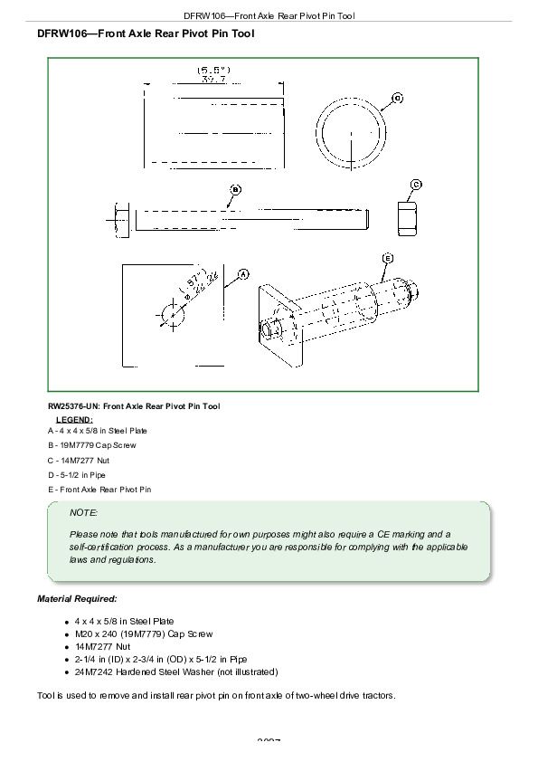
DFRW106—Front Axle Rear Pivot Pin Tool................3027
DFRW107—Front Axle Front Pivot Pin Tool................3029
DFRW117—Transmission-Hydraulic Flusher................3031
DFRW132—Differential Side Bevel Gear End Play Tool................3034
DFRW148—ActiveSeat™ Control Valve Holding Tool................3036
DFRW150—SCV-Hitch Valve Stack Lifting Bracket................3037
DFRW210—Hole Drilled in JT07201................3039
DFRW211—Transmission Support Plate................3040
DFRW212 Leak Test Assembly................3041
DFRW213—Hydraulic Trailer Brake Test / Bleed Assembly................3043
DFRW219—Wheel Tightening Stand................3046
DFRW220—Clutch Cover Removal Plate................3048
DFRW230—Seal Installer................3049
DFRW231—Guide Pins................3050
DFRW234—Hood Support Rod................3051
DFRW238—Front PTO Support Bracket................3052
DFRW248—Front PTO Output Shaft Holding Tool................3054
DFRW252—Ring Gear Retaining Tool................3056
John Deere 8R Tractors Repair (S. N. 120000—) 8225R, 8245R, 8270R, 8295R, 8320R, 8335R, 8345R, 8370R, 8400R Tractors Repair Service Manual (TM146319)


