John Deere Tractors Models 8235R, 8260R, 8285R, 8310R, 8335R, 8360R Diagnosis & Tests Service Manual (TM110219)
Catalog:
Model:
Complete Diagnostics and Tests technical manual with Electrical Wiring Diagrams for John Deere Tractors 8235R, 8260R, 8285R, 8310R, 8335R & 8360R (8R), with workshop information to maintain, diagnose, and service like professional mechanics.
John Deere Tractors 8235R, 8260R, 8285R, 8310R, 8335R, 8360R workshop Operation and Tests manual includes:
* Numbered table of contents easy to use so that you can find the information you need fast.
* Detailed sub-steps expand on repair procedure information
* Numbered instructions guide you through every repair procedure step by step.
* Troubleshooting and electrical service procedures are combined with detailed wiring diagrams for ease of use.
* Notes, cautions and warnings throughout each chapter pinpoint critical information.
* Bold figure number help you quickly match illustrations with instructions.
* Detailed illustrations, drawings and photos guide you through every procedure.
* Enlarged inset helps you identify and examine parts in detail.
tm110219 - John Deere 8R Tractors Diagnostic (S. N. —090000) (Russia S. N. 052201—055000) Technical Manual.pdf
tm110211 - Диагностика на трактори 8R (сер. ном. —090000) (Русия сер. ном. 052201—055000)
tm110214 - 8R 拖拉机诊断(序列号:之前 — 090000) (俄罗斯序列号:052201—055000)
tm110216 - Diagnostika traktorů 8R (výr. č. –090000) (Rusko výr. č. 052201–055000)
tm110226 - 8R traktorių diagnostika (S. N. —090000 ) (Rusijai skirti S. N. 052201—055000)
tm110228 - Diagnostic des tracteurs 8R (N.S. —090000) (Russie N.S. 052201—055000)
tm110229 - Diagnosehandbuch – Traktoren 8R (Seriennummern —090000) (Russland: Seriennummern 052201—055000)
tm110235 - 8R Traktor diagnosztika ( —090000 alvázszámig) (Oroszország 052201—055000 alvázszámokon)
Total Pages: 9,482 pages
File Format: PDF (bookmarked, ToC, Searchable, Printable)
Category: Diagnosis and Tests
Language: English Bulgarian Chinese Czech Lithuanian French German Hungarian
Published on 2020/01/06
MAIN SECTIONS
Foreword
GENERAL INFORMATION
Safety
General Reference
DIAGNOSTIC TROUBLE CODES
ACU Code Diagnostics
ASU Code Diagnostics
ATC Code Diagnostics
CAB Code Diagnostics
CCU Code Diagnostics
CLC Code Diagnostics
CSM Code Diagnostics
ECU Code Diagnostics
EIC Code Diagnostics
HCC Code Diagnostics
HV1 Code Diagnostics
JDLink Code Diagnostics
PDU Code Diagnostics
PTF Code Diagnostics
PTI Code Diagnostics
PTP Code Diagnostics
SCC Code Diagnostics
SFA Code Diagnostics
SV1 Code Diagnostics
SV2 Code Diagnostics
SV3 Code Diagnostics
SV4 Code Diagnostics
SV5 Code Diagnostics
SV6 Code Diagnostics
SVJ Code Diagnostics
TEC Code Diagnostics
VLC Code Diagnostics
VTI Code Diagnostics
VTV Code Diagnostics
XMA Code Diagnostics
XMB Code Diagnostics
XMC Code Diagnostics
XSA Code Diagnostics
XSB Code Diagnostics
XSC Code Diagnostics
SYSTEM DIAGNOSIS
Electrical
Control Units
PowerShift Transmission
AutoPowr™ / IVT™ Transmission
Drive Systems
Steering and Brakes
Hydraulics
Operator`s Station
ENGINES
Test and Adjustments
Theory of Operation
FUEL AND AIR
Theory of Operation
ELECTRICAL
Load Center Fuses, Relays and Ground Points
Operational Checks
Functional Schematics and Components Reference Lists
Connector Information
Harness Information
SE01 - Power Supply, Starting and Charging
SE02 - Standard Seat
SE03 - Manual A/C and Automatic Temperature Control (ATC)
SE04 - Remote Mirror Option
SE05 - Radio, Dome Lamp and Steering Column Module
SE06 - CLC - Cab Load Center Control Unit Functions
SE6A - CLC - Cab Load Center Control Unit Functions
SE06B - CLC - North American Lighting Functions
SE06C - CLC - European Lighting Functions
SE07 - Accessory Connectors
SE08 - Controller Area Network (CAN) Termination
SE09 - PDU/VTI/VTV/CSM-Cab Display and Switch Module Functions
SE10 - CAB/ASU - Cab Control Unit Functions
SE10A - CAB - CAB Control Unit Functions
SE10B - ASU - Active Seat Control Unit Functions
SE11 - VLC/CCU/PTI/PTP - Vehicle Control Unit Functions
SE11A - CCU - Chassis Control Unit Functions
SE11B - VLC - Vehicle Load Center Control Unit Functions
SE11C - PTI - AutoPowr™ / IVT™ Transmission Control Unit Functions
SE11D - PTP - PowerShift Transmission Control Unit Functions
SE13-ACU/EIC-Armrest Control Unit Functions
SE14 - SCC/HCC/SFA - Deluxe Hydraulic Control Unit Functions
SE14A - SCC - SCV Control Unit Functions
SE14B - HCC - Hitch Control Unit Functions
SE14D - SFA - Suspension Control Unit Functions
SE15 - PTF - Front PTO
SE16 - ECU
SE17 - JDLINK
SE18 -GreenStar Display
SE20 - XMC/XSC-Steering Control Unit Functions
SE21 - XMA/XMB/XSA/XSB - ActiveCommand Steering Control Unit Functions
CONTROL UNITS
General References
ACU
ASU
ATC
CAB
CCU
CLC
CSM
ECU
EIC
HCC
HV1
JDL
PDU
PTF
PTI
PTP
SCC ( - RE334185)
SCC (RE334186-)
SFA
SV1-SV6, SVJ
TEC/TEI
VLC
VTI
VTV
XMA
XMB
XMC
XSA
XSB
XSC
POWERSHIFT TRANSMISSION
Preliminary and Operational Checks
Tests and Adjustments
Theory of Operation
Schematics and Diagrams
AUTOPOWR™ / IVT™ TRANSMISSION
Preliminary and Operational Checks
Tests and Adjustments
Theory of Operation
Schematics and Diagrams
AXLES AND DIFFERENTIAL LOCK
Preliminary and Operational Checks
Tests and Adjustments
Theory of Operation
Schematics and Diagrams
MFWD
Preliminary and Operational Checks
Tests and Adjustments
Theory of Operation
Schematics and Diagrams
POWER TAKE-OFF
Preliminary and Operational Checks
Tests and Adjustments
Theory of Operation
Schematics and Diagrams
SUSPENDED FRONT AXLE
Preliminary and Operational Checks
Tests and Adjustments
Theory of Operation
Schematics and Diagrams
BRAKES
Preliminary and Operational Checks
Tests and Adjustments
Theory of Operation
Schematics and Diagrams
STEERING
Preliminary and Operational Checks
Tests and Adjustments
Theory of Operation
Schematics and Diagrams
HYDRAULICS
Preliminary and Operational Checks
Tests and Adjustments
Theory of Operation
Schematics and Diagrams
AIR CONDITIONING
Preliminary and Operational Checks
Theory of Operation
Schematics and Diagrams
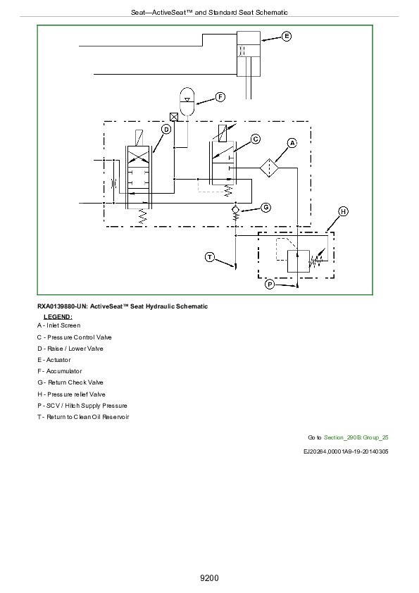
SEAT
Preliminary and Operational Checks
Tests and Adjustments
Theory of Operation
Schematics and Diagrams
SERVICE TOOLS AND INSTALLING TEST EQUIPMENT
Dealer Fabricated Tools
Service Tools and Kits
PowerShift Transmission-Install Test Equipment
AutoPowr™ / IVT™ Transmission-Install Test Equipment
Drive Systems-Install Test Equipment
Brakes-Install Test Equipment
Steering-Install Test Equipment
Hydraulics Install Test Equipment
Operator`s Station - Install Test Equipment
Table of Contents
Foreword
Section 210: GENERAL INFORMATION
Group 05: Safety
Recognize Safety Information
Understand Signal Words
Follow Safety Instructions
Wear Protective Clothing
Service Machines Safely
Stay Clear of Rotating Drivelines
Handle Fluids Safely—Avoid Fires
Prevent Battery Explosions
Prepare for Emergencies
Remove Paint Before Welding or Heating
Avoid Heating Near Pressurized Fluid Lines
Handle Starting Fluid Safely
In Case of Fire
Avoid Hot Exhaust
Clean Exhaust Filter Safely
Prevent Acid Burns
Handle Agricultural Chemicals Safely
Clean Vehicle of Hazardous Pesticides
Handling Batteries Safely
Avoid Harmful Asbestos Dust
Decommissioning — Proper Recycling and Disposal of Fluids and Components
Avoid High-Pressure Fluids
Wait Before Opening High-Pressure Fuel System
Service Accumulator Systems Safely
Protect Against High Pressure Spray
Service Cooling System Safely
Prevent Machine Runaway
Keep ROPS Installed Properly
Use Seat Belt Properly
Avoid Backover Accidents
Park Machine Safely
Support Machine Properly
Work in Clean Area
Work In Ventilated Area
Illuminate Work Area Safely
Use Proper Lifting Equipment
Service Tires Safely
Instructional Seat
Passenger Seat
Service Front-Wheel Drive Tractor Safely
Use Steps and Handholds Correctly
Transport Tractor Safely
Practice Safe Maintenance
Use Proper Tools
Construct Dealer-Made Tools Safely
Replace Safety Signs
Install All Guards
Live With Safety
Group 10: General Reference
General Reference List
Glossary of Terms
Trademarks
JIC Hydraulic Symbols
Wiring Diagram and Schematic Information
Electrical Schematic Symbols
Reading Wiring Schematics and Diagrams
Visually Inspect Electrical System
Seven Step Electrical Test Procedure
Circuit Types
Circuit Malfunctions
Relay Circuit Types
Using a Digital Multimeter
Troubleshooting Unresolved Electrical/Electronic Problems
Servicing Electronic Control Units
Welding Near Electronic Control Units
Keep Electronic Control Unit Connectors Clean
Section 211: DIAGNOSTIC TROUBLE CODES
Group ACU: ACU Code Diagnostics
ACU 000158.04 - ACU Switched Supply Voltage Low
ACU 000177.17 - Engine Speed Limited Due to Cold Oil
ACU 000237.02 - VIN Security Data Conflict
ACU 000237.14 - VIN Security Not Enabled
ACU 000237.31 - VIN Security Messages Missing
ACU 000581.07 - Transmission Not Responding to Command
ACU 000628.02 - ACU EOL Data Fault
ACU 000628.12 - ACU Programming
ACU 000629.11 - ACU Control Unit Fault
ACU 000629.12 - ACU Control Unit Fault
ACU 000630.02 - ACU Calibration Fault/Data Invalid
ACU 000630.13 - ACU Calibration Fault/Not Calibrated
ACU 000974.02 - Hand Throttle Sensor Circuit Voltage Conflict
ACU 000974.03 - Hand Throttle Sensor Circuit Voltage High
ACU 000974.04 - Hand Throttle Sensor Circuit Voltage Low
ACU 001079.03 - ACU Sensor Supply 1 Voltage High
ACU 001079.04 - ACU Sensor Supply 1 Voltage Low
ACU 001080.03 - ACU Sensor Supply 2 Voltage High
ACU 001080.04 - ACU Sensor Supply 2 Voltage Low
ACU 001504.31 - Operator Not Present While AutoTrac Is Active
ACU 001745.14 - Startup Checks Not Complete
ACU 002000.09 - ECU Message Missing
ACU 002003.09 - PTI or PTP Message Missing
ACU 002019.09 - XSA Message Missing
ACU 002020.09 - SFA Message Missing
ACU 002049.09 - CAB Message Missing
ACU 004310.09 - Vehicle Automation Communication Fault
ACU 004310.11 - Vehicle Automation Fault
ACU 004310.14 - Operator Not Present During Vehicle Automation
ACU 520283.14 - Automation Suspend State
ACU 522149.14 - Wheel Speed Limited
ACU 522149.31 - Wheel Speed Limited
ACU 522189.02 - iTEC™ Sequence 3/4 Switch Circuit Conflict
ACU 522189.03 - iTEC™ Sequence 3/4 Switch Circuits Voltage High
ACU 522189.04 - iTEC™ Sequence 3/4 Switch Circuits Voltage Low
ACU 522388.09 - Implement Communication Fault
ACU 522390.09 - Implement Communication Fault
ACU 522390.11 - Vehicle Automation Fault
ACU 523664.02 - Speed Band 1 and 2 Switches Conflict
ACU 523923.02 - SCV I Control Lever Switch/Sensor Conflict
ACU 523923.03 - SCV I Control Lever Sensor Circuit Voltage High
ACU 523923.04 - SCV I Control Lever Sensor Circuit Voltage Low
ACU 523953.02 - AutoPowr/IVT Speed Control Lever Sensor Circuit Conflict
ACU 523953.03 - AutoPowr/IVT Speed Control Lever Sensor Voltage High
ACU 523953.04 - AutoPowr/IVT Speed Control Lever Sensor Voltage Low
ACU 523954.07 - Speed Band 1 Adjustment Fault
ACU 523954.11 - Set Speed Adjuster Conflict
ACU 523955.31 - Engine Overload In Manual Mode
ACU 523958.31 - Reversing Ratio Setting Fault
ACU 523960.17 - Operator Not Present At Low Speeds
ACU 523960.31 - Operator Not Seated During Reverser Command
ACU 523961.02 - Park Engaged While In Gear
ACU 523961.07 - Park Lock Engagement Fault
ACU 523962.31 - MFWD Speed Incorrect (AutoPowr/IVT only)
ACU 523963.02 - Speed Band 1 Switch/Voltage Conflict
ACU 523966.31 - Transmission Come Home Mode
ACU 523967.02 - Speed Band 2 Switch/Voltage Conflict
ACU 523968.02 - iTEC™ 1/2 Switch Circuit Conflict
ACU 523968.03 - iTEC™ 1/2 Switch Circuits Voltage High
ACU 523968.04 - iTEC™ 1/2 Switch Circuits Voltage Low
ACU 524017.31 - Neutral Switch or Forward Slot Voltage Out Of Range
ACU 524018.31 - RHR Neutral/Park Transition Fault
ACU 524019.31 - RHR Neutral/Not-Neutral Transition Fault
ACU 524020.31 - Transmission In Gear at Power Up
ACU 524021.31 - Multiple Reverser Switches Conflict
ACU 524101.02 - SCV VI Switch/Sensor Circuit Conflict
ACU 524101.03 - SCV VI Control Lever Sensor Circuit Voltage High
ACU 524101.04 - SCV VI Control Lever Sensor Circuit Voltage Low
ACU 524102.02 - SCV V Control Lever Switch/Sensor Circuit Conflict
ACU 524102.03 - SCV V Control Lever Sensor Circuit Voltage High
ACU 524102.04 - SCV V Control Lever Sensor Circuit Voltage Low
ACU 524103.02 - SCV IV Control Lever Switch/Sensor Circuit Conflict
ACU 524103.03 - SCV IV Control Lever Sensor Circuit Voltage High
ACU 524103.04 - SCV IV Control Lever Sensor Circuit Voltage Low
ACU 524104.02 - SCV III Control Lever Switch/Sensor Circuit Conflict
ACU 524104.03 - SCV III Control Lever Sensor Circuit Voltage High
ACU 524104.04 - SCV III Control Lever Sensor Circuit Voltage Low
ACU 524105.02 - SCV II Control Lever Switch/Sensor Circuit Conflict
ACU 524105.03 - SCV II Control Lever Sensor Circuit Voltage High
ACU 524105.04 - SCV II Control Lever Sensor Circuit Voltage Low
ACU 524212.02 - Rear Hitch Control Lever Switch/Sensor Circuit Conflict
ACU 524212.03 - Rear Hitch Control Lever Sensor Circuit Voltage High
ACU 524212.04 - Rear Hitch Control Lever Sensor Circuit Voltage Low
ACU 524222.02 - Resume Switch Circuit Conflict
ACU 524224.02 - Rear PTO Switch Circuit Conflict
ACU 524254.31 - Transmission Enable Circuit Fault
Group ASU: ASU Code Diagnostics
ASU 000629.12 - ASU Control Unit Fault
ASU 524002.31 - Active Seat Pressure Control Solenoid Fault
ASU 524003.02 - Active Seat Firmness Control Switch Circuit Fault
ASU 524004.02 - Active Seat Height Control Switch Circuit Fault
ASU 524006.08 - Active Seat Vent ON Too Long
ASU 524007.08 - Active Seat Compressor Assembly ON Too Long
ASU 524008.13 - ASU Not Calibrated
ASU 524010.31 - Active Seat Raise/Lower Solenoid Circuit Fault
ASU 524011.03 - Active Seat Accelerometer Circuit Voltage High
ASU 524011.04 - Active Seat Accelerometer Circuit Voltage Low
ASU 524011.08 - Active Seat Accelerometer Circuit Fault
ASU 524012.03 - Active Seat Position Sensor Circuit Voltage High
ASU 524012.04 - Active Seat Position Sensor Circuit Voltage Low
Group ATC: ATC Code Diagnostics
ATC 000170.03 - Cab Temperature Sensor Circuit Voltage High
ATC 000170.04 - Cab Temperature Sensor Circuit Voltage Low
ATC 000628.12 - ATC Programming
ATC 000630.02 - ATC Calibration Fault/Data Invalid
ATC 000639.14 - ATC CAN Error Limit Exceeded
ATC 000871.03 - Refrigerant Pressure Sensor Circuit Voltage High
ATC 000871.04 - Refrigerant Pressure Sensor Circuit Voltage Low
ATC 000876.03 - Compressor Clutch Circuit Voltage High
ATC 000876.04 - Compressor Clutch Circuit Voltage Low
ATC 000876.10 - Excessive A/C Clutch Cycling
ATC 000876.14 - Compressor Shutoff Due to Engine Overheat
ATC 000923.03 - Circulation Blower Motor Circuit Voltage High
ATC 000923.04 - Circulation Blower Motor Circuit Voltage Low
ATC 000923.12 - Circulation Blower Motor Driver Circuit Fault
ATC 001546.03 - Water Valve Position Sensor Circuit Voltage High
ATC 001546.04 - Water Valve Position Sensor Circuit Voltage Low
ATC 001547.03 - Evaporator Temperature Sensor Circuit Voltage High
ATC 001547.04 - Evaporator Temperature Sensor Circuit Voltage Low
ATC 001548.03 - Outlet Air Temperature Sensor Circuit Voltage High
ATC 001548.04 - Outlet Air Temperature Sensor Circuit Voltage Low
ATC 001549.03 - Water Valve Motor Circuit Voltage High
ATC 001549.04 - Water Valve Motor Circuit Voltage Low
ATC 001549.07 - Water Valve Motor Mechanical Fault
ATC 001549.13 - Water Valve Motor Not Calibrated
ATC 001551.03 - Pressurizer Blower Motor Circuit Voltage High
ATC 001551.04 - Pressurizer Blower Motor Circuit Voltage Low
ATC 002000.09 - ECU Message Missing
ATC 003509.03 - ATC Sensor Supply Voltage High
ATC 003509.04 - ATC Sensor Supply Voltage Low
ATC 523848.03 - Air Flow Mode Motor Circuit Voltage High
ATC 523848.04 - Air Flow Mode Motor Circuit Voltage Low
ATC 523848.05 - Air Flow Mode Motor Circuit Current Low
ATC 523848.06 - Air Flow Mode Motor Circuit Current High
ATC 523848.07 - Air Flow Mode Motor Mechanical Fault
ATC 523848.13 - Air Flow Mode Motor Not Calibrated
ATC 524202.03 - Ambient Temperature Sensor Circuit Voltage High
ATC 524202.04 - Ambient Temperature Sensor Circuit Voltage Low
Group CAB: CAB Code Diagnostics
CAB 000091.02 - Foot Throttle Sensor Circuit Voltage Conflict
CAB 000091.03 - Foot Throttle Sensor Circuit Voltage High
CAB 000091.04 - Foot Throttle Sensor Circuit Voltage Low
CAB 000158.03 - CAB Switched Supply Voltage High
CAB 000158.04 - CAB Switched Supply Voltage Low
CAB 000237.02 - VIN Security Data Conflict
CAB 000237.14 - VIN Security Not Enabled
CAB 000237.31 - VIN Security Messages Missing
CAB 000628.02 - CAB EOL Data Fault
CAB 000629.12 - CAB Control Unit Fault
CAB 001079.03 - CAB Sensor Supply Voltage High
CAB 001079.04 - CAB Sensor Supply Voltage Low
CAB 001504.08 - Seat Switch Circuit Fault
CAB 002876.02 - Turn Signal Switch Conflict
CAB 523839.02 - Secondary Brake Switch Conflict
CAB 523841.03 - Secondary Brake Sensor Voltage High
CAB 523841.04 - Secondary Brake Sensor Voltage Low
CAB 523908.02 - Rear PTO External Switch Conflict
CAB 524016.04 - CAB Switched Supply Voltage Low
CAB 524017.13 - Left-Hand Reverser Lever Type Not Selected
CAB 524017.31 - Left-Hand Reverser Lever Power Circuit Fault
CAB 524019.31 - Left-Hand Reverser Neutral/Not-Neutral Transition Fault
CAB 524020.31 - Left-Hand Reverser Lever in Gear at Power Up
CAB 524021.31 - Left-Hand Reverser Lever Multiple Switch Circuit Fault
CAB 524166.02 - Right Brake Pedal Switch-Sensor Circuit Conflict
CAB 524166.03 - Right Brake Pedal Sensor Circuit Voltage High
CAB 524166.04 - Right Brake Pedal Sensor Circuit Voltage Low
CAB 524166.08 - Right Brake Pedal Sensor Adjustment Fault
CAB 524166.13 - Right Brake Pedal Sensor Not Calibrated
CAB 524169.02 - Left Brake Pedal Switch-Sensor Circuit Conflict
CAB 524169.03 - Left Brake Pedal Sensor Circuit Voltage High
CAB 524169.04 - Left Brake Pedal Sensor Circuit Voltage Low
CAB 524169.08 - Left Brake Pedal Sensor Adjustment Fault
CAB 524169.13 - Left Brake Pedal Sensor Not Calibrated
CAB 524173.02 - Clutch Pedal Sensor Voltage Conflict
CAB 524173.03 - Clutch Pedal Sensor Circuit Voltage High
CAB 524173.04 - Clutch Pedal Sensor Circuit Voltage Low
Group CCU: CCU Code Diagnostics
CCU 000096.03 - Fuel Level Sensor Circuit Voltage High
CCU 000096.04 - Fuel Level Sensor Circuit Voltage Low
CCU 000096.17 - Fuel Level Low
CCU 000237.02 - VIN Security Data Conflict
CCU 000237.14 - VIN Security Not Enabled
CCU 000237.31 - VIN Security Messages Missing
CCU 000567.05 - Front Differential Lock Solenoid Circuit Fault
CCU 000569.05 - Rear Differential Lock Solenoid Circuit Fault
CCU 000630.14 - Rear PTO Configuration Invalid
CCU 001079.03 - CCU Sensor Supply Voltage High
CCU 001079.04 - CCU Sensor Supply Voltage Low
CCU 001086.03 - Air Brake Pressure Sensor Circuit Voltage High
CCU 001086.04 - Air Brake Pressure Sensor Circuit Voltage Low
CCU 001086.18 - Air Brake Pressure Low
CCU 001638.00 - Hydraulic Oil Temperature Very Hot
CCU 001638.03 - Hydraulic Oil Temperature Sensor Circuit Voltage High
CCU 001638.04 - Hydraulic Oil Temperature Sensor Circuit Voltage Low
CCU 001638.16 - Hydraulic Oil Temperature Hot
CCU 001713.00 - Hydraulic Oil Filter Restricted
CCU 001883.00 - Rear PTO Overspeed
CCU 001883.01 - Rear PTO Underspeed
CCU 001883.13 - Rear PTO Not Calibrated
CCU 002392.05 - Back Up Alarm Circuit Fault
CCU 002602.01 - Hydraulic Clean Oil Reservoir Level Very Low
CCU 002602.02 - Hydraulic Clean Oil Reservoir Level Switch Fault
CCU 002602.18 - Hydraulic Oil Level Low
CCU 522260.02 - Wheel Speed Sensors Mismatch
CCU 522384.14 - 4R/5R PTO Inhibited
CCU 522390.09 - Implement Message Missing
CCU 522390.11 - Automation Abort Message Received
CCU 523698.09 - AMS Display Message Missing
CCU 523749.16 - PTO Clutch Slipping Too Long
CCU 523851.02 - iTEC™ Disabled Due To HCC/SCC/TEC
CCU 523916.00 - Hydraulic Oil Filter Restriction Sensor Bypassed Under 1500 rpm
CCU 523916.03 - Hydraulic Oil Filter Restriction Sensor Circuit Voltage High
CCU 523916.04 - Hydraulic Oil Filter Restriction Sensor Circuit Voltage Low
CCU 523916.15 - Hydraulic Oil Filter Restricted
CCU 523916.16 - Hydraulic Oil Filter Restriction Sensor Bypassed Over 1500 rpm
CCU 524016.04 - CCU Switched Supply Voltage Low
CCU 524223.03 - Differential Lock Switch Circuit Voltage High
CCU 524224.02 - PTO Switch Voltage Mismatch
CCU 524224.14 - Rear PTO Disabled
CCU 524235.05 - MFWD Solenoid Circuit Fault
CCU 524236.31 - MFWD Switch/ iTEC™ Conflict
CCU 524251.31 - Operator Not Present With Rear PTO On
CCU 524252.05 - Rear PTO Solenoid Circuit Fault
CCU 524255.31 - Rear PTO Remote Switch Enabled
Group CLC: CLC Code Diagnostics
CLC 000158.00 - CLC Switched Supply Voltage High
CLC 000158.01 - CLC Switched Supply Voltage Low
CLC 000158.17 - CLC Switched Supply Voltage Low With Engine Off
CLC 000158.18 - CLC Switched Supply Voltage Low With Engine Below 1500 RPM
CLC 000628.02 - CLC EOL Data Fault
CLC 000629.12 - CLC Control Unit Fault
CLC 001079.03 - CLC Sensor Supply Voltage High
CLC 001079.04 - CLC Sensor Supply Voltage Low
CLC 002050.06 - CLC Circuit Current High
CLC 002362.05 - Rear Roof Flood Lights Circuit Current Low
CLC 002362.06 - Rear Roof Flood Lights Circuit Current High
CLC 002364.05 - Mid-Body Flood Lights Circuit Current Low
CLC 002364.06 - Mid-Body Flood Lights Circuit Current High
CLC 002366.05 - Front Side Roof Flood Lights Circuit Current Low
CLC 002366.06 - Front Side Roof Flood Lights Circuit Current High
CLC 002368.05 - Left Turn Signal Lights Circuit Current Low
CLC 002368.06 - Left Turn Signal Lights Circuit Current High
CLC 002370.05 - Right Turn Signal Lights Circuit Current Low
CLC 002370.06 - Right Turn Signal Lights Circuit Current High
CLC 002372.05 - Brake Lights Circuit Current Low
CLC 002372.06 - Brake Lights Circuit Current High
CLC 002378.05 - Tail Light Circuit Current Low
CLC 002378.06 - Tail Lights Circuit Current High
CLC 002598.05 - Rear Side Roof Light Circuit Current Low
CLC 002598.06 - Rear Side Roof Light Circuit Current High
CLC 002863.02 - Front Wiper Switch Circuit Fault
CLC 002865.02 - Rear Wiper Switch Circuit Fault
CLC 002872.02 - Road Light Switch Circuit Fault
CLC 522310.05 - ELX Output 1 Circuit Current Low
CLC 522310.06 - ELX Output 1 Circuit Current High
CLC 522427.04 - Front Wiper Motor Park input Circuit Broken
CLC 522433.06 - Rear Wiper Motor Circuit Current High
CLC 522434.06 - Front Wiper Motor Low Speed Circuit Current High
CLC 522435.06 - Front Wiper Motor High Speed Circuit Current High
CLC 524016.05 - CAN Wake-up Circuit Current Low
CLC 524016.06 - CAN Wake-up Circuit Current High
CLC 524259.00 - CLC Temperature Above 115 Degrees Celsius
CLC 524259.15 - CLC Temperature Above 85 Degrees Celsius
CLC 524259.16 - CLC Temperature Above 100 Degrees Celsius
Group CSM: CSM Code Diagnostics
CSM 000168.04 - CSM Unswitched Supply Voltage Low
CSM 000628.02 - CSM Control Unit Fault
CSM 000628.12 - CSM Programming
CSM 000629.12 - CSM Control Unit Fault
CSM 000630.02 - CSM Memory Error
CSM 002076.09 - Radio Message Missing
CSM 003509.03 - CSM Sensor Supply Voltage High
CSM 003509.04 - CSM Sensor Supply Voltage Low
CSM 520311.02 - Radio Not in Sync
CSM 522155.02 - Auxiliary SCV Right Control Lever Switch Failure
CSM 522155.03 - Auxiliary SCV Right Control Lever Voltage High
CSM 522155.04 - Auxiliary SCV Right Control Lever Voltage Low
CSM 522156.02 - Auxiliary SCV Middle Control Lever Switch Failure
CSM 522156.03 - Auxiliary SCV Middle Control Lever Voltage High
CSM 522156.04 - Auxiliary SCV Middle Control Lever Voltage Low
CSM 522157.02 - Auxiliary SCV Left Control Lever Switch Failure
CSM 522157.03 - Auxiliary SCV Left Control Lever Voltage High
CSM 522157.04 - Auxiliary SCV Left Control Lever Voltage Low
CSM 522764.02 - ATC Temperature Setting Invalid
CSM 523343.02 - Single Lever Control Trigger Switch Fault
CSM 523343.03 - Single Lever Control Trigger Sensor Circuit Voltage High
CSM 523343.04 - Single Lever Control Trigger Sensor Circuit Voltage Low
CSM 523625.02 - ATC Fan Speed Switch Mismatch
CSM 523746.03 - Cab Switch Module Wake-up Output Voltage High
CSM 523746.04 - Cab Switch Module Wake-up Output Voltage Low
CSM 523775.02 - Single Lever Control Hand Presence Switch Fault
CSM 523776.02 - Single Lever Control Transport Lock Switch Circuit Fault
CSM 523801.02 - Single Lever Control Auxiliary Switch Fault
CSM 523804.02 - Single Lever Control Lateral Detent Switch Circuit Fault
CSM 523804.03 - Single Lever Control Lateral Sensor Circuit Voltage High
CSM 523804.04 - Single Lever Control Lateral Sensor Circuit Voltage Low
CSM 523805.02 - Single Lever Control Fore-Aft Detent Switch Circuit Fault
CSM 523805.03 - Single Lever Control Fore-Aft Sensor Circuit Voltage High
CSM 523805.04 - Single Lever Control Fore-Aft Sensor Circuit Voltage Low
Group ECU: ECU Code Diagnostics
ECU 000027.03 - EGR Valve Position Signal Out of Range High
ECU 000027.04 - EGR Valve Position Signal Out of Range Low
ECU 000027.07 - EGR Valve Desired and Actual Position Mismatch
ECU 000051.03 - Air Throttle Actuator Position Signal Out of Range High
ECU 000051.04 - Air Throttle Actuator Position Signal Out of Range Low
ECU 000051.07 - Air Throttle Actuator Desired and Actual Position Mismatch
ECU 000051.14 - Air Throttle Actuator and EGR Valve Connectors Swapped
ECU 000094.03 - Low Pressure Fuel Signal Out of Range High
ECU 000094.04 - Low Pressure Fuel Signal Out of Range Low
ECU 000094.16 - Low Pressure Fuel Signal Moderately High
ECU 000094.17 - Fuel Transfer Pump Pressure Low Least Severe
ECU 000094.18 - Low Pressure Fuel Signal Moderately Low
ECU 000097.03 - Water-in-Fuel Signal Out of Range High
ECU 000097.04 - Water-in-Fuel Signal Out of Range Low
ECU 000097.16 - Water In Fuel Detected
ECU 000100.01 - Engine Oil Pressure Signal Extremely Low
ECU 000100.02 - Engine Oil Pressure is not Zero with Engine Stopped
ECU 000100.03 - Engine Oil Pressure Signal Out of Range High
ECU 000100.04 - Engine Oil Pressure Signal Out of Range Low
ECU 000100.18 - Engine Oil Pressure Signal Moderately Low
ECU 000100.31 - Engine Oil Pressure Invalid
ECU 000102.02 - Intake Manifold Pressure Signal Invalid
ECU 000102.03 - Intake Manifold Pressure Signal Out of Range High
ECU 000102.04 - Intake Manifold Pressure Signal Out of Range Low
ECU 000102.07 - Manifold Air Pressure Signal In Range Invalid
ECU 000103.00 - Turbo Speed Signal Extremely High
ECU 000103.02 - Turbocharger Speed Signal Invalid
ECU 000103.05 - Turbo Speed Sensor Circuit Has High Resistance
ECU 000103.08 - Turbocharger Speed Signal Invalid
ECU 000103.31 - Turbocharger Speed Signal Missing
ECU 000105.00 - Intake Manifold Air Temperature Signal Extremely High
ECU 000105.03 - Intake Manifold Air Temperature Signal Out of Range High
ECU 000105.04 - Intake Manifold Air Temperature Signal Out of Range Low
ECU 000105.15 - Intake Manifold Air Temperature Signal Slightly High
ECU 000105.16 - Intake Manifold Air Temperature Signal Moderately High
ECU 000107.00 - Air Filter Pressure Differential Extremely High
ECU 000107.15 - Air Filter Pressure Differential Slightly High
ECU 000107.16 - Air Filter Pressure Differential Moderately High
ECU 000108.02 - Barometric Pressure Signal Invalid
ECU 000108.07 - Barometric Pressure Signal Mismatch
ECU 000109.01 - Engine Coolant Pressure Signal Extremely Low
ECU 000109.03 - Engine Coolant Pressure Signal Out of Range High
ECU 000109.04 - Engine Coolant Pressure Signal Out of Range Low
ECU 000109.17 - Engine Coolant Pressure Signal Slightly Low
ECU 000109.18 - Engine Coolant Pressure Signal Moderately Low
ECU 000109.31 - Engine Coolant Pressure Signal Extremely Low
ECU 000110.00 - Engine Coolant Temperature Signal Extremely High
ECU 000110.03 - Engine Coolant Temperature Signal Out of Range High
ECU 000110.04 - Engine Coolant Temperature Signal Out of Range Low
ECU 000110.15 - Engine Coolant Temperature Signal Slightly High
ECU 000110.16 - Engine Coolant Temperature Signal Moderately High
ECU 000110.17 - Engine Coolant Temperature Signal Slightly Low
ECU 000111.01 - Engine Coolant Level Extremely Low
ECU 000111.07 - Engine Coolant Level Switch Mismatch
ECU 000111.17 - Engine Coolant Level Information Switch Activated
ECU 000111.18 - Engine Coolant Level Alarm Switch Activated at Moderate Coolant Temperature
ECU 000152.12 - Control Unit Fault
ECU 000152.14 - Control Unit Fault
ECU 000152.16 - Control Unit Fault
ECU 000157.01 - Fuel Rail Pressure Signal Extremely Low
ECU 000157.03 - Fuel Rail Pressure Signal Out of Range High
ECU 000157.04 - Fuel Rail Pressure Signal Out of Range Low
ECU 000157.10 - Fuel Rail Pressure Rate of Change Abnormal
ECU 000157.16 - Fuel Rail Pressure Signal Moderately High
ECU 000157.17 - Fuel Rail Pressure Not Developed
ECU 000157.18 - Fuel Rail Pressure Signal Moderately Low
ECU 000158.12 - ECU Power Down Error
ECU 000158.17 - ECU Power Down Error
ECU 000158.31 - ECU Switched Power Error
ECU 000168.01 - Unswitched Battery Voltage Extremely Low
ECU 000168.16 - Unswitched Battery Voltage Moderately High
ECU 000168.18 - Unswitched Battery Voltage Moderately Low
ECU 000174.00 - Fuel Temperature Signal Extremely High
ECU 000174.03 - Fuel Temperature Signal Out of Range High
ECU 000174.04 - Fuel Temperature Signal Out of Range Low
ECU 000174.16 - Fuel Temperature Signal Moderately High
ECU 000189.00 - Engine Speed Derate Condition Exists
ECU 000189.31 - Engine Speed Derate Condition Exists
ECU 000190.00 - Engine Speed Extremely High
ECU 000237.02 - VIN Security Data Invalid
ECU 000237.13 - VIN Option Code Security Data Conflict
ECU 000237.31 - VIN Security Data Missing
ECU 000412.00 - EGR Temperature Signal Extremely High
ECU 000412.03 - EGR Temperature Signal Out of Range High
ECU 000412.04 - EGR Temperature Signal Out of Range Low
ECU 000412.15 - EGR Temperature Signal Slightly High
ECU 000412.16 - EGR Temperature Signal Moderately High
ECU 000611.03 - Injector Shorted to Power
ECU 000611.04 - Injector Shorted to Ground
ECU 000612.03 - Injector Drive #2 Shorted to Voltage Source
ECU 000612.04 - Injector Drive #2 Shorted to Ground
ECU 000627.01 - Electronic Injector Supply Voltage Problem
ECU 000629.12 - ECU Error
ECU 000629.13 - ECU Boot Block Error
ECU 000636.02 - Engine Position Sensor Signal Invalid
ECU 000636.05 - Engine Position Sensor Circuit Has High Resistance
ECU 000636.06 - Engine Position Sensor Circuit Has Low Resistance
ECU 000636.08 - Engine Position Sensor Signal Missing
ECU 000636.10 - Engine Position Signal Rate of Change Abnormal
ECU 000637.02 - Engine Timing Sensor Signal Invalid
ECU 000637.05 - Engine Timing Sensor Circuit Has High Resistance
ECU 000637.06 - Engine Timing Sensor Circuit Has Low Resistance
ECU 000637.07 - Engine Timing and Position Signals Out of Sync
ECU 000637.08 - Engine Timing Sensor Signal Missing
ECU 000637.10 - Crank Position Input Pattern Error
ECU 000640.31 - External Derate Commanded
ECU 000641.04 - Turbo Actuator Error
ECU 000641.05 - VGT Actuator Drive Circuit Has High Resistance
ECU 000641.07 - VGT Actuator Desired and Actual Position Mismatch During a Learn
ECU 000641.13 - Turbo Actuator Learned Value Error
ECU 000647.05 - Engine Fan Speed Increase Circuit Fault
ECU 000647.07 - Engine Fan Speed Decrease Circuit Fault
ECU 000651.02 - Injector #1 Part # Data Invalid
ECU 000651.05 - Injector #1 Circuit Has High Resistance
ECU 000651.06 - Injector #1 Circuit Has Low Resistance
ECU 000651.07 - Injector #1 Not Responding
ECU 000651.13 - Injector #1 Calibration Fault
ECU 000651.18 - Injector #1 Not Responding
ECU 000652.02 - Injector #2 Part # Data Invalid
ECU 000652.05 - Injector #2 Circuit Has High Resistance
ECU 000652.06 - Injector #2 Circuit Has Low Resistance
ECU 000652.07 - Injector #2 Not Responding
ECU 000652.13 - Injector #2 Calibration Fault
ECU 000652.18 - Injector #2 Not Responding
ECU 000653.02 - Injector #3 Part # Data Invalid
ECU 000653.05 - Injector #3 Circuit Has High Resistance
ECU 000653.06 - Injector #3 Circuit Has Low Resistance
ECU 000653.07 - Injector #3 Not Responding
ECU 000653.13 - Injector #3 Calibration Fault
ECU 000653.18 - Injector #3 Not Responding
ECU 000654.02 - Injector #4 Part # Data Invalid
ECU 000654.05 - Injector #4 Circuit Has High Resistance
ECU 000654.06 - Injector #4 Circuit Has Low Resistance
ECU 000654.07 - Injector #4 Not Responding
ECU 000654.13 - Injector #4 Calibration Fault
ECU 000654.18 - Injector #4 Not Responding
ECU 000655.02 - Injector #5 Part # Data Invalid
ECU 000655.05 - Injector #5 Circuit Has High Resistance
ECU 000655.06 - Injector #5 Circuit Has Low Resistance
ECU 000655.07 - Injector #5 Not Responding
ECU 000655.13 - Injector #5 Calibration Fault
ECU 000655.18 - Injector #5 Not Responding
ECU 000656.02 - Injector #6 Part # Data Invalid
ECU 000656.05 - Injector #6 Circuit Has High Resistance
ECU 000656.06 - Injector #6 Circuit Has Low Resistance
ECU 000656.07 - Injector #6 Not Responding
ECU 000656.13 - Injector #6 Calibration Fault
ECU 000656.18 - Injector #6 Not Responding
ECU 000695.19 - Unapproved Engine Speed Request
ECU 000970.31 - Key Authentication Invalid
ECU 001075.02 - Low Pressure Fuel Pump Data Erratic
ECU 001075.04 - Low Pressure Fuel Pump Supply Voltage Low
ECU 001075.06 - Low Pressure Fuel Pump Circuit Has Low Resistance
ECU 001075.09 - Low Pressure Fuel Pump Loss of Communication
ECU 001075.12 - Low Pressure Fuel Pump Error Detected
ECU 001075.15 - Low Pressure Fuel Pump Temperature Slightly High
ECU 001110.31 - Engine Protection System Activated
ECU 001136.00 - ECU Temperature Signal Extremely High
ECU 001136.02 - ECU Temperature Signal Invalid
ECU 001136.16 - ECU Temperature Signal Moderately High
ECU 001172.03 - Compressor Inlet Temperature Signal Out of Range High
ECU 001172.04 - Compressor Inlet Temperature Signal Out of Range Low
ECU 001172.12 - Intake Air Temperature Error
ECU 001176.07 - Intake Air Pressure Mismatch
ECU 001176.12 - Intake Air Pressure Error
ECU 001180.00 - Turbine Inlet Temperature Signal Extremely High
ECU 001180.16 - Turbine Inlet Temperature Signal Moderately High
ECU 001209.03 - Exhaust Manifold Pressure Signal Out of Range High
ECU 001209.04 - Exhaust Manifold Pressure Signal Out of Range Low
ECU 001209.07 - Exhaust Manifold Pressure Mismatch
ECU 001347.01 - Suction Control Valve Sticking and Fuel Rail Pressure Extremely Low
ECU 001347.03 - High Pressure Fuel Pump Control Valve Signal Out of Range High
ECU 001347.05 - High Pressure Fuel Pump Solenoid #1 Circuit Has High Resistance
ECU 001347.06 - Suction Control Valve Circuit Has Low Resistance
ECU 001347.07 - High Pressure Fuel Pump Not Able to Meet Required Rail Pressure
ECU 001347.16 - Suction Control Valve Sticking and Fuel Rail Pressure Moderately High
ECU 001347.18 - Suction Control Valve Sticking and Fuel Rail Pressure Slightly Low
ECU 001550.05 - Air Conditioner Compressor Current Low
ECU 001550.06 - Air Conditioner Compressor Current High
ECU 001568.02 - Torque Curve Selection Error
ECU 001569.31 - Engine in Derate Condition
ECU 001639.01 - Fan Speed Extremely Low
ECU 001639.16 - Fan Speed Moderately High
ECU 001639.18 - Fan Speed Moderately Low
ECU 002005.09 - ACU Message Missing
ECU 002005.14 - Communication Error
ECU 002005.19 - Communication Error
ECU 002006.09 - EIC Message Missing
ECU 002006.14 - Incorrect CAN Message Received From Source Address 6
ECU 002006.19 - Communication Error
ECU 002030.09 - VLC Message Missing
ECU 002040.09 - PDU Message Missing
ECU 002071.09 - CCU Message Missing
ECU 002629.03 - Fixed Turbocharger Compressor Outlet Temperature Signal Out of Range High
ECU 002629.04 - Fixed Turbocharger Compressor Outlet Temperature Signal Out of Range Low
ECU 002630.00 - Charge Air Cooler Outlet Temperature Signal Extremely High
ECU 002630.03 - Charge Air Cooler Outlet Temperature Signal Out of Range High
ECU 002630.04 - Charge Air Cooler Outlet Temperature Signal Out of Range Low
ECU 002630.15 - Charge Air Cooler Outlet Temperature Signal Slightly High
ECU 002630.16 - Charge Air Cooler Outlet Temperature Signal Moderately High
ECU 002659.02 - EGR Mass Flow Rate Data Invalid
ECU 002659.03 - EGR Flow Signal Out of Range High
ECU 002659.04 - EGR Flow Signal Out of Range Low
ECU 002659.07 - EGR Flow Signal Mismatch
ECU 002659.14 - EGR Flow Rate Data Invalid
ECU 002659.15 - EGR Mass Flow Rate Data Slightly High
ECU 002659.17 - EGR Mass Flow Rate Data Slightly Low
ECU 002790.16 - Calculated Turbine Outlet Temperature Moderately High
ECU 002791.02 - EGR Valve Position Signal Invalid
ECU 002791.03 - EGR Valve Position Signal Out of Range High
ECU 002791.04 - EGR Valve Position Signal Out of Range Low
ECU 002791.05 - EGR Valve Drive Circuit Has High Resistance
ECU 002791.06 - EGR Valve Drive Circuit Has Low Resistance
ECU 002791.07 - EGR Valve Not Reaching Expected Position
ECU 002791.13 - EGR Valve Calibration Change Error
ECU 002791.31 - EGR Valve Calibration Change Over a Long Time
ECU 002795.02 - VGT Calibration Version Invalid
ECU 002795.03 - VGT Vane Position Signal Out of Range High
ECU 002795.04 - VGT Vane Position Signal Out of Range Low
ECU 002795.07 - VGT Actuator Not Reaching Expected Position
ECU 002795.10 - VGT Vane Position Signal Rate of Change Abnormal
ECU 002795.13 - VGT Calibration Error
ECU 002797.03 - Injector High Voltage Supply #1 Out of Range High
ECU 002797.05 - Injector High Voltage Supply #1 Circuit Has High Resistance
ECU 002797.06 - Injector High Voltage Supply #1 Circuit Has Low Resistance
ECU 002798.03 - Injector High Voltage Supply #2 Out of Range High
ECU 002798.05 - Injector High Voltage Supply #2 Circuit Has High Resistance
ECU 002798.06 - Injector High Voltage Supply #2 Circuit Has Low Resistance
ECU 003246.00 - DPF Outlet Temperature Extremely High
ECU 003246.12 - DPF Outlet Temperature Error
ECU 003251.00 - DPF Differential Pressure Signal Not Responding
ECU 003251.02 - DPF Differential Pressure Signal Invalid
ECU 003251.03 - DPF Differential Pressure Signal Out of Range High
ECU 003251.04 - DPF Differential Pressure Signal Out of Range Low
ECU 003251.07 - DPF Differential Pressure Signal Fault
ECU 003353.31 - Alternator Fault
ECU 003464.05 - Air Throttle Actuator Drive Circuit Has High Resistance
ECU 003464.06 - Air Throttle Actuator Drive Circuit Has Low Resistance
ECU 003464.07 - Air Throttle Actuator Desired and Actual Position Mismatch During a Learn
ECU 003464.13 - Air Throttle Actuator Calibration Error
ECU 003471.03 - Fuel Dosing Control Valve Signal Out of Range High
ECU 003471.04 - Fuel Dosing Control Valve Signal Out of Range Low
ECU 003471.05 - Fuel Dosing Control Valve Circuit Has High Resistance
ECU 003471.07 - Fuel Dosing Control Valve Stuck
ECU 003471.11 - Fuel Dosing Control Valve Circuit Fault
ECU 003480.01 - Fuel Dosing Inlet Pressure Signal Extremely Low
ECU 003480.03 - Fuel Dosing Inlet Pressure Signal Out of Range High
ECU 003480.04 - Fuel Dosing Inlet Pressure Signal Out of Range Low
ECU 003480.07 - Fuel Dosing Inlet Sensor Desired and Actual Pressure Mismatch
ECU 003480.18 - Fuel Dosing Inlet Pressure Moderately Low
ECU 003482.03 - Fuel Dosing Shutoff Valve Signal Out of Range High
ECU 003482.04 - Fuel Dosing Shutoff Valve Signal Out of Range Low
ECU 003482.05 - Fuel Dosing Shutoff Valve Circuit Has High Resistance
ECU 003482.16 - Fuel Dosing Shutoff Valve Stuck Open
ECU 003509.03 - Sensor Supply #1 Voltage Out of Range High
ECU 003509.04 - Sensor Supply #1 Voltage Out of Range Low
ECU 003510.03 - Sensor Supply #2 Voltage Out of Range High
ECU 003510.04 - Sensor Supply #2 Voltage Out of Range Low
ECU 003511.03 - Sensor Supply #3 Voltage Out of Range High
ECU 003511.04 - Sensor Supply #3 Voltage Out of Range Low
ECU 003512.03 - Sensor Supply #4 Voltage Out of Range High
ECU 003512.04 - Sensor Supply #4 Voltage Out of Range Low
ECU 003513.03 - Sensor Supply #5 Voltage Out of Range High
ECU 003513.04 - Sensor Supply #5 Voltage Out of Range Low
ECU 003514.03 - Sensor Supply #6 Voltage Out of Range High
ECU 003514.04 - Sensor Supply #6 Voltage Out of Range Low
ECU 003556.16 - Fuel Dosing Injector Stuck Closed
ECU 003556.18 - Fuel Dosing Injector Stuck Open
ECU 003597.01 - Injector High Voltage Supply Extremely Low
ECU 003711.14 - Exhaust Temperature Management Failure With Load
ECU 003711.31 - Exhaust Temperature Management Failure With Load
ECU 003719.00 - Calculated Soot Level Extremely High
ECU 003719.10 - Calculated Soot Loading Rate of Change Abnormal
ECU 003719.13 - Excessive DPF Recovery Attempts
ECU 003719.14 - Calculated Soot Is At The Service Only Level
ECU 003719.16 - Calculated Soot Level Moderately High
ECU 003720.15 - Calculated Ash Level Slightly High
ECU 003720.16 - Calculated Ash Level Moderately High
ECU 003936.00 - Calculated Excessive Unintended Combustables In DPF Mulitiple Fault Occurrences
ECU 003936.15 - Calculated Unintended Combustables In DPF Multiple Fault Occurrence
ECU 003936.16 - Calculated Excessive Unintended Combustables In DPF Single Fault Occurrence
ECU 004077.03 - Fuel Dosing Outlet Pressure Signal Out of Range High
ECU 004077.04 - Fuel Dosing Outlet Pressure Signal Out of Range Low
ECU 004077.07 - Fuel Dosing Outlet Pressure Signal Invalid
ECU 004490.12 - Intake Air Humidity Error
ECU 004765.00 - DOC Inlet Temperature Extremely High
ECU 004765.12 - DOC Inlet Temperature Error
ECU 004766.12 - DOC Outlet Temperature Error
ECU 004766.15 - DOC Outlet Temperature Slightly High
ECU 004766.16 - DOC Outlet Temperature Moderately High
ECU 004766.17 - DOC Outlet Temperature Slightly Low
ECU 004766.18 - DOC Outlet Temperature Moderately Low
ECU 004795.31 - DPF Missing
ECU 005018.00 - Calculated Excessive Unintended Combustables In DOC Mulitiple Fault Occurrences
ECU 005018.15 - Calculated Unintended Combustables In DOC Single Fault Occurrence
ECU 005018.16 - Calculated Unintended Combustables In DOC Multiple Fault Occurrences
ECU 005125.03 - Sensor Supply #7 Voltage Out of Range High
ECU 005125.04 - Sensor Supply #7 Voltage Out of Range Low
ECU 005126.03 - Sensor Supply #8 Voltage Out of Range High
ECU 005126.04 - Sensor Supply #8 Voltage Out of Range Low
ECU 005298.01 - DOC Effiency Extremely Low
ECU 005456.00 - Fuel Dosing Inlet Temperature Signal Extremely High
ECU 005456.01 - Fuel Dosing Inlet Temperature Signal Extremely Low
ECU 005456.03 - Fuel Dosing Inlet Temperature Signal Out of Range High
ECU 005456.04 - Fuel Dosing Inlet Temperature Signal Out of Range Low
ECU 521192.11 - Immobilizer Control Device Fault
ECU 521214.09 - Immobilizer Control Device Fault
ECU 521214.14 - Immobilizer Control Device Fault
ECU 522458.02 - Fuel Dosing Pump Data Erratic
ECU 522458.03 - Fuel Dosing Pump Supply Voltage High
ECU 522458.04 - Fuel Dosing Pump Supply Voltage Low
ECU 522458.06 - Fuel Dosing Pump Circuit Has Low Resistance
ECU 522458.09 - Fuel Dosing Pump Loss of Communication
ECU 522458.15 - Fuel Dosing Pump Temperature Slightly High
ECU 522494.09 - Intake Air Sensor Communication Error
ECU 522495.09 - Exhaust Filter Temperature Module Loss of Communication
ECU 523744.09 - A/C Clutch Message Not Received
Group EIC: EIC Code Diagnostics
EIC 000628.02 - EIC EOL Data Fault
EIC 000630.13 - EIC Calibration Fault/Not Calibrated
EIC 001237.31 - Failed Key Authentication
EIC 002000.09 - ECU Message Missing
EIC 002029.09 - Immobilizer Message Missing
EIC 002029.12 - EIC Control Unit Fault
EIC 002139.09 - CSM Message Missing
EIC 003695.14 - Diesel Particulate Filter Regeneration Fault
EIC 003719.15 - Diesel Particulate Filter Regeneration Fault
EIC 521192.12 - Immobilizer Control Device Fault
EIC 521192.13 - Immobilizer Control Device Fault
EIC 521214.11 - Immobilizer Control Device Fault
EIC 521214.31 - Immobilizer Control Device Fault
EIC 521321.09 - Immobilizer Message Missing
EIC 521321.12 - Immobilizer Control Device Fault
EIC 521322.07 - Immobilizer Control Device Fault
EIC 521322.31 - Immobilizer Control Device Fault
EIC 523702.14 - EIC Control Unit Fault
EIC 523702.31 - EIC Control Unit Fault
Group HCC: HCC Code Diagnostics
HCC 000158.04 - HCC Switched Supply Voltage Low
HCC 000168.04 - HCC Unswitched Supply Voltage Low
HCC 000190.02 - Rear Hitch Calibration Fault/Engine Speed Low
HCC 000629.12 - HCC Control Unit Fault
HCC 000630.13 - HCC Calibration Fault/Not Calibrated
HCC 001079.03 - HCC Sensor Supply Voltage High
HCC 001079.04 - HCC Sensor Supply Voltage Low
HCC 001638.02 - HCC Calibration Fault/Hydraulic Oil Temperature Low
HCC 001873.02 - Rear Hitch Position Sensor Circuit Voltage Fault
HCC 001873.03 - Rear Hitch Position Sensor Circuit Voltage High
HCC 001873.04 - Rear Hitch Position Sensor Circuit Voltage Low
HCC 001873.11 - Rear Hitch Position Restricted During Calibration
HCC 001873.13 - HCC Calibration Fault/Rear Hitch Position Sensor Circuit
HCC 001881.03 - Rear Hitch Draft Sensor Circuit Voltage High
HCC 001881.04 - Rear Hitch Draft Sensor Circuit Voltage Low
HCC 001881.13 - HCC Calibration Fault/Rear Hitch Draft Sensor Circuit
HCC 002005.09 - ACU Message Missing
HCC 002071.09 - CCU Message Missing
HCC 002139.09 - CSM Message Missing
HCC 002152.09 - HV I Message Missing
HCC 002602.18 - Hydraulic Oil Level Low
HCC 003509.03 - HCC Sensor Supply Voltage High
HCC 003509.04 - HCC Sensor Supply Voltage Low
HCC 003509.06 - HCC Sensor Circuit Current High
HCC 521000.02 - Rear Hitch External Switch Circuit Fault
HCC 521000.31 - Rear Hitch External Switch Circuit Conflict
HCC 521001.02 - HCC Calibration Fault/Rear Hitch Pressure Valve Gain
HCC 521001.07 - Rear Hitch Control Valve Circuit Fault
HCC 521002.07 - Rear Hitch Control Valve Circuit Fault
HCC 521002.11 - Rear Hitch Control Valve Circuit Fault
HCC 521002.13 - Rear Hitch Control Valve Calibration Fault
HCC 522390.09 - Implement Communication Fault
HCC 522390.11 - Vehicle Automation Fault
HCC 523652.02 - Wire Connector Fault/Incompatible Harness Location
HCC 523788.02 - Hydraulic Option Configuration Changed Since Power-up
HCC 523788.14 - Hydraulic Option Configuration Change Not Allowed
HCC 523910.02 - HCC Control Unit Fault
HCC 523950.13 - Rear Hitch Calibration not Performed Correctly
HCC 523952.31 - Rear Hitch Disabled/HCC Configuration
HCC 524016.04 - HCC Switched Supply Voltage Low/Rear Hitch Solenoids
HCC 524212.19 - Rear Hitch Control Lever Fault Message Received
HCC 524212.31 - Rear Hitch Lever Command Missing
Group HV1: HV1 Code Diagnostics
HV1 000158.03 - HV I Switched Supply Voltage High
HV1 000158.04 - HV I Switched Supply Voltage Low
HV1 002035.09 - HCC Message Missing
HV1 004084.07 - HV I Not in FLOAT Position
HV1 004084.16 - HV I Overshot Commanded Position
HV1 004084.18 - HV I Failed to Reach Commanded Position
HV1 004085.07 - HV I Not in NEUTRAL Position
HV1 004085.12 - HV1 Control Unit Fault
Group JDL: JDLink Code Diagnostics
JDL Codes
Group PDU: PDU Code Diagnostics
PDU 000628.02 - PDU EOL Data Fault
PDU 000629.12 - PDU Control Unit Fault
PDU 002000.09 - ECU Message Missing
PDU 002003.09 - PTI or PTP Message Missing
PDU 002005.09 - ACU Message Missing
PDU 002011.09 - BRC Message Missing
PDU 002020.09 - SFA Message Missing
PDU 002025.09 - ATC Message Missing
PDU 002030.09 - VLC Message Missing
PDU 002034.09 - SCC Message Missing
PDU 002035.09 - HCC Message Missing
PDU 002038.09 - VTI Message Missing
PDU 002040.09 - PDU Message Missing
PDU 002049.09 - CAB Message Missing
PDU 002050.09 - CLC Message Missing
PDU 002054.09 - ASU Message Missing
PDU 002071.09 - CCU Message Missing
PDU 002139.09 - CSM Message Missing
PDU 002240.09 - TEC Message Missing
PDU 523329.08 - Steering Message Missing
PDU 523329.13 - Steering Startup Checks
PDU 523330.02 - Steering Message Missing
Group PTF: PTF Code Diagnostics
PTF 000123.03 - Front PTO Clutch Pressure Sensor Circuit Voltage High
PTF 000123.04 - Front PTO Clutch Pressure Sensor Circuit Voltage Low
PTF 000123.16 - Front PTO Clutch Pressure High
PTF 000123.18 - Front PTO Clutch Pressure Low
PTF 000168.03 - PTF Unswitched Supply Voltage High
PTF 000168.04 - PTF Unswitched Supply Voltage Low
PTF 000237.02 - VIN Security Data Conflict
PTF 000237.14 - VIN Security Not Enabled
PTF 000237.31 - VIN Security Messages Missing
PTF 000628.02 - PTF EOL Data Fault
PTF 000628.12 - PTF Programming
PTF 000630.14 - Front PTO Configuration Invalid
PTF 001882.00 - Front PTO Overspeed
PTF 001882.01 - Front PTO Underspeed
PTF 001882.13 - Front PTO Not Calibrated
PTF 001882.15 - Front PTO Overloaded, Rated Power Exceeded
PTF 002000.09 - ECU Message Missing
PTF 002003.09 - PTI or PTP Message Missing
PTF 002049.09 - Cab Message Missing
PTF 002071.09 - CCU Message Missing
PTF 002140.09 - AIC Message Missing
PTF 003510.03 - Front PTO Sensor Supply Voltage High
PTF 003510.04 - Front PTO Sensor Supply Voltage Low
PTF 520634.01 - Front PTO Lube Return Pressure Low
PTF 520634.03 - Front PTO Return Oil Pressure Sensor Circuit Voltage High
PTF 520634.04 - Front PTO Return Oil Pressure Sensor Circuit Voltage Low
PTF 523749.16 - PTO Clutch Slipping Too Long
PTF 523904.31 - Operator Not Present With Front PTO On
PTF 523905.03 - Front PTO Solenoid Circuit Fault
PTF 523905.04 - Front PTO Solenoid Circuit Fault
PTF 523905.05 - Front PTO Circuit Fault
PTF 523905.06 - Front PTO Circuit Fault
PTF 523906.00 - Front PTO Oil Temperature High
PTF 523906.03 - Front PTO Oil Temperature Sensor Circuit Voltage High
PTF 523906.04 - Front PTO Oil Temperature Sensor Circuit Voltage Low
PTF 523906.15 - Front PTO Oil Temperature High
PTF 524216.02 - Front PTO Switch Circuit Fault
PTF 524216.31 - Front PTO Disabled
Group PTI: PTI Code Diagnostics
PTI 000127.01 - Transmission Enable Pressure Very Low
PTI 000158.01 - PTI Switched Supply Voltage Low
PTI 000168.01 - PTI Unswitched Supply Voltage Low
PTI 000177.17 - Transmission Oil Temperature Low/Calibration Inhibited
PTI 000190.00 - Engine Overspeed
PTI 000190.02 - Speed Mismatch - ECU Message with PTI Calculation
PTI 000191.00 - Transmission Overspeed
PTI 000191.02 - Transmission Output Speed Mismatch
PTI 000619.05 - Park Brake Solenoid Circuit Fault
PTI 000628.02 - PTI EOL Data Fault
PTI 000628.12 - PTI Programming
PTI 000629.12 - PTI Control Unit Fault
PTI 000630.13 - PTI Hydro Calibration Fault
PTI 000630.14 - PTI Clutch Calibration Fault
PTI 000734.05 - Low Clutch Solenoid Circuit Fault
PTI 000735.05 - High Clutch Solenoid Circuit Fault
PTI 000736.05 - Reverse Brake Solenoid Circuit Fault
PTI 000737.05 - Clutch 1 (C1) Solenoid Circuit Fault
PTI 000738.05 - Clutch 2 (C2) Solenoid Circuit Fault
PTI 000739.05 - Clutch 3 (C3) Solenoid Circuit Fault
PTI 000754.18 - Clutch Enable Pressure Low/LC Engaged
PTI 000755.18 - Clutch Enable Pressure Low/HC Engaged
PTI 000756.18 - Clutch Enable Pressure Low/RB Engaged
PTI 001079.04 - PTI Sensor Supply Voltage Low
PTI 002000.09 - ECU Message Missing
PTI 002005.09 - ACU Message Missing
PTI 523911.05 - Hydro Ring Unit (RU) Control Solenoid Circuit Fault
PTI 523911.13 - Hydro Ring Unit (RU) Calibration Fault
PTI 523912.05 - Hydro Clutch Unit (CU) Solenoid Circuit Fault
PTI 523912.13 - Hydro Clutch Unit (CU) Calibration Fault
PTI 523913.05 - Loop Flush Cut-Off Solenoid Circuit Fault
PTI 523917.07 - Synchronizer Speed Mismatch
PTI 523917.08 - Synchronizer Engagement Fault
PTI 523917.17 - CU Idler Speed Low at Start-Up
PTI 524226.08 - Direction Sensing Incorrect
PTI 524228.05 - Park Sump Block Solenoid Circuit Fault
PTI 524228.11 - Park Sump Block Valve Fault
PTI 524230.03 - Unexpected Enable Pressure
PTI 524230.05 - Clutch Enable Solenoid Circuit Fault
PTI 524232.01 - Park Brake Pressure Low/Gear Commanded
PTI 524232.02 - Park Brake Pressure Sensor Fault
PTI 524232.04 - Park Brake Pressure Sensor Circuit Voltage Low
PTI 524232.14 - Park Brake Pressure Low in Come Home Mode
PTI 524232.16 - Park Brake Pressure High/Park Commanded
PTI 524232.17 - Park Brake Pressure Low/Park Not Commanded
PTI 524232.18 - Park Brake Pressure Low
PTI 524233.00 - Hydro Ring Unit (RU) Overspeed
PTI 524233.02 - Ring Unit (RU) Speed Incorrect
PTI 524233.07 - Hydro Speed Incorrect/PowerZero™
PTI 524233.15 - Hydro Speed Incorrect/Park Engaged
PTI 524233.16 - Hydro Speed Incorrect/Park Not Engaged
PTI 524233.17 - Hydro Ring Unit (RU) Speed Low At Start-Up
PTI 524234.02 - Clutch Enable Pressure Incorrect
PTI 524234.04 - Clutch Enable Pressure Sensor Circuit Voltage Low
PTI 524237.31 - Reverser Park and Neutral Switches On
PTI 524238.31 - Reverser, Park and Neutral Signals Off
PTI 524239.31 - No Motion/Engine Running
PTI 524240.14 - No Motion/Come Home Mode
PTI 524241.02 - Carrier Speed or Hydro Ring Gear Speed Incorrect
PTI 524241.11 - Synchronizer Engagement Fault/Clutch Control
PTI 524242.00 - Transmission Pressures High
PTI 524243.31 - PTI Park/ACU Gear Command Conflict
PTI 524244.31 - PTI Park/ACU Neutral Command Conflict
PTI 524245.31 - PTI Neutral/ACU Gear Command Conflict
PTI 524247.02 - Carrier Speed Incorrect
PTI 524247.17 - Carrier Speed Low at Start-Up
PTI 524248.31 - Vehicle Motion With Park Brake Engaged
PTI 524249.31 - Operator Not Seated With Transmission In Neutral
PTI 524250.31 - Park Brake Previously Failed/May Not Hold
PTI 524253.02 - ACU Not Commanding Park At Power Up
PTI 524254.03 - Transmission Enable Circuit Voltage High
PTI 524254.04 - Transmission Enable Circuit Voltage Low
Group PTP: PTP Code Diagnostics
PTP 000084.07 - Vehicle Motion During Calibration
PTP 000084.18 - Engine Off With Transmission In Gear
PTP 000092.16 - Engine Load Excessive In 4R/5R
PTP 000123.18 - Clutch Pressure Low
PTP 000127.01 - Transmission Oil Pressure Very Low
PTP 000127.03 - Clutch Pressure Sensor Circuit Voltage High
PTP 000127.04 - Clutch Pressure Sensor Circuit Voltage Low
PTP 000158.01 - PTP Switched Supply Voltage Low
PTP 000168.01 - PTP Unswitched Supply Voltage Low
PTP 000168.03 - PTP Unswitched Supply Voltage High
PTP 000168.18 - PTP Unswitched Supply Voltage Low in Tow Mode
PTP 000177.17 - Top Gear Limited Due to Cold Oil
PTP 000190.00 - Engine Speed too High
PTP 000190.01 - Engine Speed too Low
PTP 000190.18 - Engine Speed too Low for Transmission Conditions
PTP 000619.05 - Park Brake Solenoid Circuit Fault
PTP 000628.02 - PTP EOL Data Fault
PTP 000628.12 - PTP Programming
PTP 000629.12 - PTP Control Unit Fault
PTP 000630.02 - PTP Calibration Fault/Data Invalid
PTP 000630.14 - Transmission Not Calibrated
PTP 000734.05 - Clutch 1 (C1) Valve Circuit Fault
PTP 000734.06 - Clutch 1 (C1) Valve Current High
PTP 000735.05 - Clutch 2 (C2) Valve Circuit Fault
PTP 000735.06 - Clutch 2 (C2) Valve Current High
PTP 000736.05 - Clutch 3 (C3) Valve Circuit Fault
PTP 000736.06 - Clutch 3 (C3) Valve Current High
PTP 000737.05 - Clutch 4 (C4) Valve Circuit Fault
PTP 000737.06 - Clutch 4 (C4) Valve Current High
PTP 000738.05 - Clutch R (CR) Valve Circuit Fault
PTP 000738.06 - Clutch R (CR) Valve Current High
PTP 000739.05 - D Clutch (DC) Valve Circuit Fault
PTP 000739.06 - D Clutch (DC) Valve Current High
PTP 000810.02 - Countershaft Speed Sensor Fault
PTP 002000.09 - ECU Message Missing
PTP 002005.09 - ACU Message Missing
PTP 002019.09 - XSA Message Missing
PTP 002020.09 - SFA Message Missing
PTP 002049.09 - CAB Message Missing
PTP 521936.05 - Lube Cutoff Valve Circuit Fault
PTP 523953.02 - Speed Control Lever Sensor Circuit Conflict
PTP 523960.31 - Operator Not Seated During Reverser Command
PTP 524020.31 - Transmission In Gear at Power Up
PTP 524228.05 - Park Sump Block Solenoid Circuit Fault
PTP 524228.11 - Park Sump Block Valve Fault
PTP 524232.03 - Park Brake Pressure Sensor Circuit Voltage High
PTP 524232.04 - Park Brake Pressure Sensor Circuit Voltage Low
PTP 524232.16 - Park Brake Pressure High/Park Commanded
PTP 524232.17 - Park Brake Pressure Low/Park Not Commanded
PTP 524239.31 - No Motion/Engine Running
PTP 524248.31 - Vehicle Motion With Park Brake Engaged
PTP 524250.31 - Park Brake Previously Failed/May Not Hold
PTP 524267.15 - C Clutch (CC) or D Clutch (DC) Slipping Too Long
PTP 524267.16 - Clutch Slipping Too Long
PTP 524267.31 - A Brake (AB) or B Clutch (BC) Slipping Too Long
PTP 524271.05 - C Clutch (CC) Valve Circuit Fault
PTP 524271.06 - C Clutch (CC) Valve Current High
PTP 524272.05 - B Clutch (BC) Valve Circuit Fault
PTP 524272.06 - B Clutch (BC) Valve Current High
PTP 524273.05 - A Brake (AB ) Valve Circuit Fault
PTP 524273.06 - A Brake (AB) Valve Current High
PTP 524277.00 - Engine Speed Too High For Downshift
PTP 524279.31 - Operator Not Seated With Transmission In Neutral
PTP 524280.31 - Vehicle Motion While Shifting to Park
Group SCC: SCC Code Diagnostics
SCC 000158.04 - SCC Switched Supply Voltage Low
SCC 000168.03 - SCC Unswitched Supply Voltage High
SCC 000168.04 - SCC Unswitched Supply Voltage Low
SCC 000629.12 - SCC Control Unit Fault
SCC 000630.13 - SCC Calibration Fault/Not Calibrated
SCC 000639.12 - SCC CAN Message Overflow
SCC 000639.14 - SCC CAN Error Limit Exceeded
SCC 001079.03 - SCC Sensor Supply Voltage High
SCC 001079.04 - SCC Sensor Supply Voltage Low
SCC 002000.09 - ECU Message Missing
SCC 002006.09 - EIC Message Missing
SCC 002049.09 - CAB Message Missing
SCC 002071.09 - CCU Message Missing
SCC 002139.09 - CSM Message Missing
SCC 002140.09 - ACU Message Missing
SCC 002161.09 - SV I Message Missing
SCC 002162.09 - SV II Message Missing
SCC 002163.09 - SV III Message Missing
SCC 002164.09 - SV IV Message Missing
SCC 002165.09 - SV V Message Missing
SCC 002166.09 - SV VI Message Missing
SCC 002170.09 - Front Hitch Message Missing
SCC 002602.18 - Hydraulic Oil Level Low
SCC 003509.03 - SCC Sensor Supply Voltage High
SCC 003509.04 - SCC Sensor Supply Voltage Low
SCC 521000.02 - Front External Switch Circuit Fault
SCC 522157.19 - Front Hitch Control Lever Fault Message Received
SCC 522157.31 - Front Hitch Control Lever Command Missing
SCC 522164.31 - Operator Out of Seat With Front Hitch ON
SCC 523216.03 - SCC Unswitched Supply Voltage High to SV I and SV II
SCC 523216.04 - SCC Unswitched Supply Voltage Low to SV I and SV II
SCC 523217.03 - SCC Unswitched Supply Voltage High to SV J (Front Hitch)
SCC 523217.04 - SCC Unswitched Supply Voltage Low to SV J (Front Hitch)
SCC 523218.03 - SCC Unswitched Supply Voltage High to ILS
SCC 523218.04 - SCC Unswitched Supply Voltage Low to ILS
SCC 523219.03 - SCC Unswitched Supply Voltage High to SV III and SV IV
SCC 523219.04 - SCC Unswitched Supply Voltage Low to SV III and SV IV
SCC 523272.02 - Front Hitch External Switch Circuit Fault
SCC 523652.02 - Wire Connector Fault
SCC 523693.02 - Missing SV I External Control Message for 10 Seconds
SCC 523693.09 - Missing SV I External Control Message for 1 Second
SCC 523693.19 - SV I External Control Fault Message Received
SCC 523694.02 - Missing SV II External Control Message for 10 Seconds
SCC 523694.09 - Missing SV II External Control Message for 1 Second
SCC 523694.19 - SV II External Control Fault Message Received
SCC 523695.02 - Missing SV V External Control Message for 10 Seconds
SCC 523695.09 - Missing SV V External Control Message for 1 Second
SCC 523695.19 - SV V External Control Fault Message Received
SCC 523696.02 - Missing SV VI External Control Message for 10 Seconds
SCC 523696.09 - Missing SV VI External Control Message for 1 Second
SCC 523696.19 - SV VI External Control Fault Message Received
SCC 523775.19 - Single Lever Control Hand Presence Switch Fault Message Received
SCC 523775.31 - Single Lever Control Hand Presence Switch Message Not Received
SCC 523776.19 - Single Lever Control Transport Lock Switch Fault Message Received
SCC 523783.03 - SCV Remote Position Sensor 4 Circuit Voltage High
SCC 523783.04 - SCV Remote Position Sensor 4 Circuit Voltage Low
SCC 523783.07 - SCV Remote Position Sensor 4 Fault/Unexpected Response
SCC 523783.13 - SCV Remote Position Sensor 4 Wrong Polarity
SCC 523784.03 - SCV Remote Position Sensor 3 Circuit Voltage High
SCC 523784.04 - SCV Remote Position Sensor 3 Circuit Voltage Low
SCC 523784.07 - SCV Remote Position Sensor 3 Fault/Unexpected Response
SCC 523784.13 - SCV Remote Position Sensor 3 Wrong Polarity
SCC 523785.01 - Lost Laser Track/Electro-Hydraulic External Control Not Available for SV III
SCC 523785.03 - SCV Remote Position Sensor 2 Circuit Voltage High
SCC 523785.04 - SCV Remote Position Sensor 2 Circuit Voltage Low
SCC 523785.07 - SCV Remote Position Sensor 2 Fault/Unexpected Response
SCC 523785.13 - SCV Remote Position Sensor 2 Wrong Polarity
SCC 523786.01 - Lost Laser Track/Electro-Hydraulic External Control Not Available for SV I
SCC 523786.03 - SCV Remote Position Sensor 1 Circuit Voltage High
SCC 523786.04 - SCV Remote Position Sensor 1 Circuit Voltage Low
SCC 523786.07 - SCV Remote Position Sensor 1 Fault/Unexpected Response
SCC 523786.13 - SCV Remote Position Sensor 1 Wrong Polarity
SCC 523788.02 - Hydraulic Option Configuration Changed Since Power-Up
SCC 523788.14 - Hydraulic Option Configuration Changed Without Disconnect
SCC 523788.31 - Hydraulic Option Configuration Invalid
SCC 523801.19 - Single Lever Control Auxiliary Switch Fault Message Received
SCC 523804.19 - Single Lever Control Lateral Sensor Fault Message Received
SCC 523805.19 - Single Lever Control Fore-Aft Sensor Fault Message Received
SCC 523910.02 - SCC Control Unit Fault
SCC 523923.19 - SCV I Control Lever Fault Message Received
SCC 523923.31 - SCV I Control Lever Command Missing
SCC 523942.31 - Operator Out of Seat With SV VI ON
SCC 523943.31 - Operator Out of Seat With SV V ON
SCC 523944.31 - Operator Out of Seat With SV IV ON
SCC 523945.31 - Operator Out of Seat With SV III ON
SCC 523946.31 - Operator Out of Seat With SV II ON
SCC 523947.31 - Operator Out of Seat With SV I ON
SCC 524015.02 - Missing SV III External Control Message for 10 Seconds
SCC 524015.09 - Missing SV III External Control Message for 1 Second
SCC 524015.19 - SV III External Control Fault Message Received
SCC 524038.02 - Missing SV IV External Control Message for 10 Seconds
SCC 524038.09 - Missing SV IV External Control Message for 1 Second
SCC 524038.19 - SV IV External Control Fault Message Received
SCC 524101.19 - SCV VI Lever Fault Message Received
SCC 524101.31 - SCV VI Lever Command Missing
SCC 524102.19 - SCV V Control Lever Fault Message Received
SCC 524102.31 - SCV V Control Lever Command Missing
SCC 524103.19 - SCV IV Control Lever Fault Message Received
SCC 524103.31 - SCV IV Control Lever Command Missing
SCC 524104.19 - SCV III Control Lever Fault Message Received
SCC 524104.31 - SCV III Control Lever Command Missing
SCC 524105.19 - SCV II Control Lever Fault Message Received
SCC 524105.31 - SCV II Control Lever Command Missing
Group SFA: SFA Code Diagnostics
SFA 000158.04 - SFA Switched Supply Voltage Low
SFA 000168.04 - SFA Unswitched Supply Voltage Low
SFA 000629.12 - SFA Control Unit Fault
SFA 000630.02 - Suspension Calibration Fault/Data Invalid
SFA 000630.13 - Suspension Not Calibrated
SFA 002003.09 - PTI or PTP Message Missing
SFA 002005.09 - ACU Message Missing
SFA 002049.09 - CAB Message Missing
SFA 002071.09 - CCU Message Missing
SFA 002602.18 - Hydraulic Oil Level Low
SFA 003509.03 - Suspension Sensor Supply Voltage High
SFA 003509.04 - Suspension Sensor Supply Voltage Low
SFA 522287.05 - Front Suspension Dampening Solenoid B Circuit Current Low
SFA 522287.06 - Front Suspension Dampening Solenoid B Circuit Current High
SFA 522288.05 - Front Suspension Dampening Solenoid A Circuit Current Low
SFA 522288.06 - Front Suspension Dampening Solenoid A Circuit Current High
SFA 522290.02 - Front Suspension Right Position Sensor Calibration Fault
SFA 522290.03 - Front Suspension Right Position Sensor Circuit Voltage High
SFA 522290.04 - Front Suspension Right Position Sensor Circuit Voltage Low
SFA 523368.02 - SFA Control Unit Fault
SFA 523652.02 - Wire Connector Fault/ Incompatible Harness Location
SFA 523847.05 - Front Suspension Spring Rate Decrease Solenoid Circuit Current Low
SFA 523847.06 - Front Suspension Spring Rate Decrease Solenoid Circuit Current High
SFA 523902.07 - Front Suspension Not Responding To Raise Command
SFA 523903.07 - Front Suspension Not Responding To Lower Command
SFA 523910.02 - SFA Control Unit Fault
SFA 523948.05 - Suspension Raise Circuit Current Low
SFA 523948.06 - Suspension Raise Circuit Current High
SFA 523949.05 - Suspension Lower Circuit Current Low
SFA 523949.06 - Suspension Lower Circuit Current High
SFA 523950.02 - Front Suspension Left Position Sensor Calibration Fault
SFA 523950.03 - Front Suspension Left Position Sensor Circuit Voltage High
SFA 523950.04 - Front Suspension Left Position Sensor Circuit Voltage Low
SFA 523950.13 - Front Suspension Left Position Sensor Calibration Fault
SFA 523964.05 - Front Suspension Spring Rate Increase Solenoid Circuit Current Low
SFA 523964.06 - Front Suspension Spring Rate Increase Solenoid Circuit Current High
SFA 523974.02 - Front Suspension Pressure Sensor Calibration Fault
SFA 523974.03 - Front Suspension Pressure Sensor Circuit Voltage High
SFA 523974.04 - Front Suspension Pressure Sensor Circuit Voltage Low
Group SV1: SV1 Code Diagnostics
SV1 000158.03 - SV I Switched Supply Voltage High
SV1 000158.04 - SV I Switched Supply Voltage Low
SV1 002034.09 - SCC Message Missing
SV1 004084.07 - SV I Not in Float Position
SV1 004084.16 - SV I Overshot Commanded Position
SV1 004084.18 - SV I Failed to Reach Commanded Position
SV1 004085.07 - SV I Not in NEUTRAL Position
SV1 004085.12 - SV I Control Unit Fault
Group SV2: SV2 Code Diagnostics
SV2 000158.03 - SV II Switched Supply Voltage High
SV2 000158.04 - SV II Switched Supply Voltage Low
SV2 002034.09 - SCC Message Missing
SV2 004084.07 - SV II Not in Float Position
SV2 004084.16 - SV II Overshot Commanded Position
SV2 004084.18 - SV II Failed to Reach Commanded Position
SV2 004085.07 - SV II Not in Neutral Position
SV2 004085.12 - SV II Control Unit Fault
Group SV3: SV3 Code Diagnostics
SV3 000158.03 - SV III Switched Supply Voltage High
SV3 000158.04 - SV III Switched Supply Voltage Low
SV3 002034.09 - SCC Message Missing
SV3 004084.07 - SV III Not in Float Position
SV3 004084.16 - SV III Overshot Commanded Position
SV3 004084.18 - SV III Failed to Reach Commanded Position
SV3 004085.07 - SV III Not in Neutral Position
SV3 004085.12 - SV III Control Unit Fault
Group SV4: SV4 Code Diagnostics
SV4 000158.03 - SV IV Switched Supply Voltage High
SV4 000158.04 - SV IV Switched Supply Voltage Low
SV4 002034.09 - SCC Message Missing
SV4 004084.07 - SV IV Not in Float Position
SV4 004084.16 - SV IV Overshot Commanded Position
SV4 004084.18 - SV IV Failed to Reach Commanded Position
SV4 004085.07 - SV IV Not in Neutral Position
SV4 004085.12 - SV IV Control Unit Fault
Group SV5: SV5 Code Diagnostics
SV5 000158.03 - SV V Switched Supply Voltage High
SV5 000158.04 - SV V Switched Supply Voltage Low
SV5 002034.09 - SCC Message Missing
SV5 004084.07 - SV V Not in Float Position
SV5 004084.16 - SV V Overshot Commanded Position
SV5 004084.18 - SV V Failed to Reach Commanded Position
SV5 004085.07 - SV V Not in Neutral Position
SV5 004085.12 - SV V Control Unit Fault
Group SV6: SV6 Code Diagnostics
SV6 000158.03 - SV VI Switched Supply Voltage High
SV6 000158.04 - SV VI Switched Supply Voltage Low
SV6 002034.09 - SCC Message Missing
SV6 004084.07 - SV VI Not in Float Position
SV6 004084.16 - SV VI Overshot Commanded Position
SV6 004084.18 - SV VI Failed to Reach Commanded Position
SV6 004085.07 - SV VI Not in Neutral Position
SV6 004085.12 - SV VI Control Unit Fault
Group SVJ: SVJ Code Diagnostics
SVJ 000158.03 - SV J (Front Hitch) Switched Supply Voltage High
SVJ 000158.04 - SV J (Front Hitch) Switched Supply Voltage Low
SVJ 002034.09 - SCC Message Missing
SVJ 004084.07 - SV J (Front Hitch) Not in Float Position
SVJ 004084.16 - SV J (Front Hitch) Overshot Commanded Position
SVJ 004084.18 - SV J (Front Hitch) Failed to Reach Commanded Position
SVJ 004085.07 - SV J (Front Hitch) Not in Neutral Position
SVJ 004085.12 - SVJ (Front Hitch) Control Unit Fault
Group TEC: TEC Code Diagnostics
TEC 000628.12 - TEC Programming
TEC 000629.12 - TEC Control Unit Fault
TEC 000630.02 - TEC Calibration Fault/Data Invalid
TEC 000639.12 - TEC CAN Message Overflow
TEC 000639.14 - TEC Vehicle CAN Error Limit Exceeded
TEC 001231.12 - TEC Implement CAN Message Overflow
TEC 522550.14 - ISO Compliant and Non-ISO Compliant Devices on Implement Bus
Group VLC: VLC Code Diagnostics
VLC 000628.02 - VLC EOL Data Fault
VLC 000629.12 - VLC Control Unit Fault
VLC 001542.04 - Wake Up Signal Voltage Low
VLC 002030.06 - VLC Circuit Current High
VLC 002050.09 - CLC Message Missing
VLC 002348.05 - High Beam Lights Circuit Current Low
VLC 002348.06 - High Beam Lights Circuit Current High
VLC 002350.05 - Low Beam Lights Circuit Current Low
VLC 002350.06 - Low Beam Lights Circuit Current High
VLC 002354.05 - Front Outer Flood Lights Circuit Current Low
VLC 002354.06 - Front Outer Flood Lights Circuit Current High
VLC 002356.05 - Front Inner Flood Lights Circuit Current Low
VLC 002356.06 - Front Inner Flood Lights Circuit Current High
VLC 522310.06 - ELX Output 2 Circuit Current High
VLC 522311.05 - Rear Washer Pump Circuit Current Low
VLC 522311.06 - Rear Washer Pump Circuit Current High
VLC 522312.05 - Front Washer Pump Circuit Current Low
VLC 522312.06 - Front Washer Pump Circuit Current High
VLC 522620.05 - Horn Circuit Current Low
VLC 522620.06 - Horn Circuit Current High
Group VTI: VTI Code Diagnostics
VTI 000442.00 - Display Unit Temperature High
VTI 000442.01 - Display Unit Temperature Low
VTI 000609.12 - CAN Bus Communication Failure
VTI 002040.09 - PDU Message Missing
VTI 521780.12 - USB Internal Failure
VTI 523310.12 - Flash Memory Read/Write Failure
VTI 524050.12 - Clock Functionality May Be Invalid
Group VTV: VTV Code Diagnostics
VTV - VTV Codes
Group XMA: XMA Code Diagnostics
XMA 000168.01 - ActiveCommand Steering A-Box Supply Voltage Low
XMA 000609.12 - Incorrect Software
XMA 000628.12 - ActiveCommand Steering Control Units Programming
XMA 000629.02 - ActiveCommand Steering A-Box Control Unit Fault
XMA 000629.12 - ActiveCommand Steering A-Box Control Unit Fault
XMA 000639.08 - Vehicle CAN Bus Fault
XMA 000639.12 - Vehicle CAN Bus Fault
XMA 000639.14 - Vehicle CAN Bus Fault
XMA 000701.02 - Incompatible Harness on ActiveCommand Steering A-Box Control Unit
XMA 000702.12 - Hardware Self-Test Failed
XMA 000704.09 - System Start-up Checks Failed
XMA 000705.09 - System Motion Checks Failed
XMA 000708.08 - ActiveCommand Steering A-Box Control Unit Fault
XMA 000708.10 - ActiveCommand Steering A-Box Control Unit Fault
XMA 000708.16 - ActiveCommand Steering A-Box Control Unit Fault
XMA 000708.18 - ActiveCommand Steering A-Box Control Unit Fault
XMA 000708.20 - ActiveCommand Steering A-Box Control Unit Fault
XMA 000708.21 - ActiveCommand Steering A-Box Control Unit Fault
XMA 000709.08 - ActiveCommand Steering A-Box Control Unit Fault
XMA 000709.10 - ActiveCommand Steering A-Box Control Unit Fault
XMA 000709.16 - ActiveCommand Steering A-Box Control Unit Fault
XMA 000709.18 - ActiveCommand Steering A-Box Control Unit Fault
XMA 000709.20 - ActiveCommand Steering A-Box Control Unit Fault
XMA 000709.21 - ActiveCommand Steering A-Box Control Unit Fault
XMA 000710.08 - ActiveCommand Steering A-Box Control Unit Fault
XMA 000710.10 - ActiveCommand Steering A-Box Control Unit Fault
XMA 000710.16 - ActiveCommand Steering A-Box Control Unit Fault
XMA 000710.18 - ActiveCommand Steering A-Box Control Unit Fault
XMA 000710.20 - ActiveCommand Steering A-Box Control Unit Fault
XMA 000710.21 - ActiveCommand Steering A-Box Control Unit Fault
XMA 000711.08 - ActiveCommand Steering A-Box Control Unit Fault
XMA 000711.10 - ActiveCommand Steering A-Box Control Unit Fault
XMA 000711.16 - ActiveCommand Steering A-Box Control Unit Fault
XMA 000711.18 - ActiveCommand Steering A-Box Control Unit Fault
XMA 000711.20 - ActiveCommand Steering A-Box Control Unit Fault
XMA 000711.21 - ActiveCommand Steering A-Box Control Unit Fault
XMA 001231.08 - ActiveCommand Steering CAN Bus Fault
XMA 001231.12 - ActiveCommand Steering CAN Bus Fault
XMA 001231.14 - ActiveCommand Steering CAN Bus Fault
XMA 002000.09 - ECU Messages Missing
XMA 002003.09 - PTP/PTI Messages Missing
XMA 002005.09 - ACU Messages Missing
XMA 002019.09 - XSA Messages Missing on ActiveCommand Steering CAN Bus
XMA 002049.09 - CAB Messages Missing
XMA 002071.09 - CCU Messages Missing
XMA 002200.09 - XMB Messages Missing on ActiveCommand Steering CAN Bus
XMA 002201.09 - XSB Messages Missing on ActiveCommand Steering CAN Bus
XMA 002240.09 - TEC Messages Missing
XMA 003841.08 - ActiveCommand Steering A-Box Control Unit Fault
XMA 003841.16 - ActiveCommand Steering A-Box Control Unit Fault
XMA 003841.18 - ActiveCommand Steering A-Box Control Unit Fault
XMA 003841.20 - ActiveCommand Steering A-Box Control Unit Fault
XMA 003841.21 - ActiveCommand Steering A-Box Control Unit Fault
XMA 003842.08 - ActiveCommand Steering A-Box Control Unit Fault
XMA 003842.16 - ActiveCommand Steering A-Box Control Unit Fault
XMA 003842.18 - ActiveCommand Steering A-Box Control Unit Fault
XMA 003842.20 - ActiveCommand Steering A-Box Control Unit Fault
XMA 003842.21 - ActiveCommand Steering A-Box Control Unit Fault
XMA 003843.08 - ActiveCommand Steering A-Box Control Unit Fault
XMA 003843.16 - ActiveCommand Steering A-Box Control Unit Fault
XMA 003843.18 - ActiveCommand Steering A-Box Control Unit Fault
XMA 003843.20 - ActiveCommand Steering A-Box Control Unit Fault
XMA 003843.21 - ActiveCommand Steering A-Box Control Unit Fault
XMA 003844.08 - ActiveCommand Steering A-Box Control Unit Fault
XMA 003844.16 - ActiveCommand Steering A-Box Control Unit Fault
XMA 003844.18 - ActiveCommand Steering A-Box Control Unit Fault
XMA 003844.20 - ActiveCommand Steering A-Box Control Unit Fault
XMA 003844.21 - ActiveCommand Steering A-Box Control Unit Fault
XMA 003850.03 - ActiveCommand Steering A-Box Control Unit Fault
XMA 003850.04 - ActiveCommand Steering A-Box Control Unit Fault
XMA 003851.03 - ActiveCommand Steering A-Box Control Unit Fault
XMA 003851.04 - ActiveCommand Steering A-Box Control Unit Fault
XMA 003852.02 - ActiveCommand Steering A-Box Control Unit Fault
XMA 003852.03 - ActiveCommand Steering A-Box Control Unit Fault
XMA 003852.04 - ActiveCommand Steering A-Box Control Unit Fault
XMA 003857.08 - ActiveCommand Steering A-Box Control Unit Fault
XMA 003857.16 - ActiveCommand Steering A-Box Control Unit Fault
XMA 003857.18 - ActiveCommand Steering A-Box Control Unit Fault
XMA 003858.08 - ActiveCommand Steering A-Box Control Unit Fault
XMA 003858.16 - ActiveCommand Steering A-Box Control Unit Fault
XMA 003858.18 - ActiveCommand Steering A-Box Control Unit Fault
XMA 003859.09 - XMB and XSB Messages Missing on ActiveCommand Steering CAN Bus
XMA 003870.03 - ActiveCommand Steering A-Box Control Unit Fault
XMA 003870.04 - ActiveCommand Steering A-Box Control Unit Fault
XMA 003870.15 - ActiveCommand Steering A-Box Control Unit Fault
XMA 003872.03 - ActiveCommand Steering A-Box Control Unit Fault
XMA 003872.04 - ActiveCommand Steering A-Box Control Unit Fault
XMA 003873.00 - ActiveCommand Steering A-Box Control Unit Fault
XMA 003873.01 - ActiveCommand Steering A-Box Control Unit Fault
XMA 003873.03 - ActiveCommand Steering A-Box Control Unit Fault
XMA 003873.04 - ActiveCommand Steering A-Box Control Unit Fault
XMA 003874.03 - ActiveCommand Steering A-Box Control Unit Fault
XMA 003874.04 - ActiveCommand Steering A-Box Control Unit Fault
XMA 003874.15 - ActiveCommand Steering A-Box Control Unit Fault
XMA 003882.02 - ActiveCommand Steering A-Box Control Unit Fault
XMA 522269.07 - Steer Right Valve 1 Stuck Open
XMA 522270.07 - Steer Left Valve 1 Stuck Open
XMA 522777.13 - Steering Wheel Module Not Calibrated
XMA 522791.13 - Gyroscope Not Calibrated
XMA 522807.01 - ActiveCommand Steering A-Box Control Unit Fault
XMA 522837.16 - Front Brake Solenoid Current High
XMA 522837.18 - Front Brake Solenoid Current Low
XMA 522838.03 - Front Brake Solenoid Short To Voltage Source
XMA 522838.05 - Front Brake Solenoid Open Circuit
XMA 522838.06 - Front Brake Solenoid Short To Ground
XMA 522838.16 - Front Brake Solenoid Current High
XMA 522838.18 - Front Brake Solenoid Current Low
XMA 522845.16 - Steer Right Solenoid 1 Current High
XMA 522845.18 - Steer Right Solenoid 1 Current Low
XMA 522846.03 - Steer Right Solenoid 1 Short To Voltage Source
XMA 522846.05 - Steer Right Solenoid 1 Open Circuit
XMA 522846.06 - Steer Right Solenoid 1 Short To Ground
XMA 522846.16 - Steer Right Solenoid 1 Current High
XMA 522846.18 - Steer Right Solenoid 1 Current Low
XMA 522847.16 - Steer Left Solenoid 1 Current High
XMA 522847.18 - Steer Left Solenoid 1 Current Low
XMA 522848.03 - Steer Left Solenoid 1 Short To Voltage Source
XMA 522848.05 - Steer Left Solenoid 1 Open Circuit
XMA 522848.06 - Steer Left Solenoid 1 Short To Ground
XMA 522848.16 - Steer Left Solenoid 1 Current High
XMA 522848.18 - Steer Left Solenoid 1 Current Low
XMA 522920.09 - XMA Timed Out Waiting for XSA
XMA 522976.12 - ActiveCommand Steering A-Box Control Unit Fault
XMA 523137.14 - Steering System Fault
XMA 523329.09 - XMB and XSB Messages Missing on ActiveCommand Steering CAN Bus
XMA 523329.14 - Steering System Fault
XMA 523789.13 - Wheel Angle Sensors Not Calibrated
XMA 523795.13 - Steering Valve Not Calibrated
XMA 523840.00 - Front Brake Pressure High
XMA 523840.01 - Front Brake Pressure Low
XMA 523844.07 - Front Brake Valve Stuck Open
XMA 523844.13 - Front Brake Not Calibrated
XMA 523925.09 - XMA Messages Missing on ActiveCommand Steering CAN Bus
XMA 524055.02 - ActiveCommand Steering A-Box Control Unit Fault
XMA 524055.12 - ActiveCommand Steering A-Box Control Unit Fault
Group XMB: XMB Code Diagnostics
XMB 000168.01 - ActiveCommand Steering B-Box Supply Voltage Low
XMB 000609.12 - Incorrect Software
XMB 000628.12 - ActiveCommand Steering Control Units Programming
XMB 000629.02 - ActiveCommand Steering B-Box Control Unit Fault
XMB 000629.12 - ActiveCommand Steering B-Box Control Unit Fault
XMB 000639.08 - Vehicle CAN Bus Fault
XMB 000639.12 - Vehicle CAN Bus Fault
XMB 000639.14 - Vehicle CAN Bus Fault
XMB 000701.02 - Incompatible Harness on ActiveCommand Steering B-Box Control Unit
XMB 000702.12 - Hardware Self-Test Failed
XMB 000704.09 - System Start-up Checks Failed
XMB 000705.09 - System Motion Checks Failed
XMB 000708.08 - ActiveCommand Steering B-Box Control Unit Fault
XMB 000708.10 - ActiveCommand Steering B-Box Control Unit Fault
XMB 000708.16 - ActiveCommand Steering B-Box Control Unit Fault
XMB 000708.18 - ActiveCommand Steering B-Box Control Unit Fault
XMB 000708.20 - ActiveCommand Steering B-Box Control Unit Fault
XMB 000708.21 - ActiveCommand Steering B-Box Control Unit Fault
XMB 000709.08 - ActiveCommand Steering B-Box Control Unit Fault
XMB 000709.10 - ActiveCommand Steering B-Box Control Unit Fault
XMB 000709.16 - ActiveCommand Steering B-Box Control Unit Fault
XMB 000709.18 - ActiveCommand Steering B-Box Control Unit Fault
XMB 000709.20 - ActiveCommand Steering B-Box Control Unit Fault
XMB 000709.21 - ActiveCommand Steering B-Box Control Unit Fault
XMB 000710.08 - ActiveCommand Steering B-Box Control Unit Fault
XMB 000710.10 - ActiveCommand Steering B-Box Control Unit Fault
XMB 000710.16 - ActiveCommand Steering B-Box Control Unit Fault
XMB 000710.18 - ActiveCommand Steering B-Box Control Unit Fault
XMB 000710.20 - ActiveCommand Steering B-Box Control Unit Fault
XMB 000710.21 - ActiveCommand Steering B-Box Control Unit Fault
XMB 000711.08 - ActiveCommand Steering B-Box Control Unit Fault
XMB 000711.10 - ActiveCommand Steering B-Box Control Unit Fault
XMB 000711.16 - ActiveCommand Steering B-Box Control Unit Fault
XMB 000711.18 - ActiveCommand Steering B-Box Control Unit Fault
XMB 000711.20 - ActiveCommand Steering B-Box Control Unit Fault
XMB 000711.21 - ActiveCommand Steering B-Box Control Unit Fault
XMB 001231.08 - ActiveCommand Steering CAN Bus Fault
XMB 001231.12 - ActiveCommand Steering CAN Bus Fault
XMB 001231.14 - ActiveCommand Steering CAN Bus Fault
XMB 002000.09 - ECU Messages Missing
XMB 002003.09 - PTI/PTP Messages Missing
XMB 002005.09 - ACU Messages Missing
XMB 002019.09 - XSA Messages Missing on ActiveCommand Steering CAN Bus
XMB 002049.09 - CAB Messages Missing
XMB 002071.09 - CCU Messages Missing
XMB 002198.09 - XMA Messages Missing on ActiveCommand Steering CAN Bus
XMB 002201.09 - XSB Messages Missing on ActiveCommand Steering CAN Bus
XMB 002240.09 - TEC Messages Missing
XMB 003841.08 - ActiveCommand Steering B-Box Control Unit Fault
XMB 003841.16 - ActiveCommand Steering B-Box Control Unit Fault
XMB 003841.18 - ActiveCommand Steering B-Box Control Unit Fault
XMB 003841.20 - ActiveCommand Steering B-Box Control Unit Fault
XMB 003841.21 - ActiveCommand Steering B-Box Control Unit Fault
XMB 003842.08 - ActiveCommand Steering B-Box Control Unit Fault
XMB 003842.16 - ActiveCommand Steering B-Box Control Unit Fault
XMB 003842.18 - ActiveCommand Steering B-Box Control Unit Fault
XMB 003842.20 - ActiveCommand Steering B-Box Control Unit Fault
XMB 003842.21 - ActiveCommand Steering B-Box Control Unit Fault
XMB 003843.08 - ActiveCommand Steering B-Box Control Unit Fault
XMB 003843.16 - ActiveCommand Steering B-Box Control Unit Fault
XMB 003843.18 - ActiveCommand Steering B-Box Control Unit Fault
XMB 003843.20 - ActiveCommand Steering B-Box Control Unit Fault
XMB 003843.21 - ActiveCommand Steering B-Box Control Unit Fault
XMB 003844.08 - ActiveCommand Steering B-Box Control Unit Fault
XMB 003844.16 - ActiveCommand Steering B-Box Control Unit Fault
XMB 003844.18 - ActiveCommand Steering B-Box Control Unit Fault
XMB 003844.20 - ActiveCommand Steering B-Box Control Unit Fault
XMB 003844.21 - ActiveCommand Steering B-Box Control Unit Fault
XMB 003849.01 - ActiveCommand Steering B-Box Control Unit Fault
XMB 003850.03 - ActiveCommand Steering B-Box Control Unit Fault
XMB 003850.04 - ActiveCommand Steering B-Box Control Unit Fault
XMB 003850.16 - ActiveCommand Steering B-Box Control Unit Fault
XMB 003850.18 - ActiveCommand Steering B-Box Control Unit Fault
XMB 003851.03 - ActiveCommand Steering B-Box Control Unit Fault
XMB 003851.04 - ActiveCommand Steering B-Box Control Unit Fault
XMB 003853.03 - ActiveCommand Steering B-Box Control Unit Fault
XMB 003853.04 - ActiveCommand Steering B-Box Control Unit Fault
XMB 003854.03 - ActiveCommand Steering B-Box Control Unit Fault
XMB 003854.04 - ActiveCommand Steering B-Box Control Unit Fault
XMB 003855.03 - ActiveCommand Steering B-Box Control Unit Fault
XMB 003855.04 - ActiveCommand Steering B-Box Control Unit Fault
XMB 003856.01 - ActiveCommand Steering B-Box Control Unit Fault
XMB 003857.08 - ActiveCommand Steering B-Box Control Unit Fault
XMB 003857.16 - ActiveCommand Steering B-Box Control Unit Fault
XMB 003857.18 - ActiveCommand Steering B-Box Control Unit Fault
XMB 003858.08 - ActiveCommand Steering B-Box Control Unit Fault
XMB 003858.16 - ActiveCommand Steering B-Box Control Unit Fault
XMB 003858.18 - ActiveCommand Steering B-Box Control Unit Fault
XMB 003859.09 - XMA and XSA Messages Missing on ActiveCommand Steering CAN Bus
XMB 003861.02 - ActiveCommand Steering B-Box Control Unit Fault
XMB 003861.03 - ActiveCommand Steering B-Box Control Unit Fault
XMB 003861.04 - ActiveCommand Steering B-Box Control Unit Fault
XMB 003861.08 - ActiveCommand Steering B-Box Control Unit Fault
XMB 003862.03 - ActiveCommand Steering B-Box Control Unit Fault
XMB 003862.04 - ActiveCommand Steering B-Box Control Unit Fault
XMB 003862.08 - ActiveCommand Steering B-Box Control Unit Fault
XMB 003869.14 - ActiveCommand Steering B-Box Control Unit Fault
XMB 003870.03 - ActiveCommand Steering B-Box Control Unit Fault
XMB 003870.04 - ActiveCommand Steering B-Box Control Unit Fault
XMB 003870.15 - ActiveCommand Steering B-Box Control Unit Fault
XMB 003872.00 - ActiveCommand Steering B-Box Control Unit Fault
XMB 003872.01 - ActiveCommand Steering B-Box Control Unit Fault
XMB 003872.03 - ActiveCommand Steering B-Box Control Unit Fault
XMB 003872.04 - ActiveCommand Steering B-Box Control Unit Fault
XMB 003874.03 - ActiveCommand Steering B-Box Control Unit Fault
XMB 003874.04 - ActiveCommand Steering B-Box Control Unit Fault
XMB 003874.15 - ActiveCommand Steering B-Box Control Unit Fault
XMB 003881.01 - ActiveCommand Steering B-Box Control Unit Fault
XMB 003882.02 - ActiveCommand Steering B-Box Control Unit Fault
XMB 522269.07 - Steer Right Valve 2 Stuck Open
XMB 522270.07 - Steer Left Valve 2 Stuck Open
XMB 522279.07 - Secondary Brake Valve Stuck Open
XMB 522279.13 - Secondary Brake Not Calibrated
XMB 522280.00 - Secondary Brake Pressure High
XMB 522280.01 - Secondary Brake Pressure Low
XMB 522777.13 - Steering Wheel Module Not Calibrated
XMB 522807.01 - ActiveCommand Steering B-Box Control Unit Switched Voltage Low
XMB 522837.16 - Steering Wheel Brake Solenoid Current High
XMB 522837.18 - Steering Wheel Brake Solenoid Current Low
XMB 522838.03 - Steering Wheel Brake Solenoid Short to Voltage Source
XMB 522838.05 - Steering Wheel Brake Solenoid Open Circuit
XMB 522838.06 - Steering Wheel Brake Solenoid Short To Ground
XMB 522838.13 - Steering Wheel Brake Not Calibrated
XMB 522838.16 - Steering Wheel Brake Solenoid Current High
XMB 522838.18 - Steering Wheel Brake Solenoid Current Low
XMB 522843.16 - Secondary Brake Solenoid Current High
XMB 522843.18 - Secondary Brake Solenoid Current Low
XMB 522844.03 - Secondary Brake Solenoid Short To Voltage Source
XMB 522844.05 - Secondary Brake Solenoid Open Circuit
XMB 522844.06 - Secondary Brake Solenoid Short To Ground
XMB 522844.16 - Secondary Brake Solenoid Current High
XMB 522844.18 - Secondary Brake Solenoid Current Low
XMB 522845.16 - Steer Right Solenoid 2 Current High
XMB 522845.18 - Steer Right Solenoid 2 Current Low
XMB 522846.03 - Steer Right Solenoid 2 Short To Voltage Source
XMB 522846.05 - Steer Right Solenoid 2 Open Circuit
XMB 522846.06 - Steer Right Solenoid 2 Short To Ground
XMB 522846.16 - Steer Right Solenoid 2 Current High
XMB 522846.18 - Steer Right Solenoid 2 Current Low
XMB 522847.16 - Steer Left Solenoid 2 Current High
XMB 522847.18 - Steer Left Solenoid 2 Current Low
XMB 522848.03 - Steer Left Solenoid 2 Short To Voltage Source
XMB 522848.05 - Steer Left Solenoid 2 Open Circuit
XMB 522848.06 - Steer Left Solenoid 2 Short To Ground
XMB 522848.16 - Steer Left Solenoid 2 Current High
XMB 522848.18 - Steer Left Solenoid 2 Current Low
XMB 522920.09 - XMB Timed Out Waiting for XSB
XMB 522976.12 - ActiveCommand Steering B-Box Control Unit Fault
XMB 523137.14 - Steering System Fault
XMB 523329.09 - XMA and XSA Messages Missing on ActiveCommand Steering CAN Bus
XMB 523329.14 - Steering System Fault
XMB 523789.13 - Wheel Angle Sensors Not Calibrated
XMB 523795.13 - Steering Valve Not Calibrated
XMB 523925.09 - XMA Messages Missing on ActiveCommand Steering CAN Bus
XMB 524055.02 - ActiveCommand Steering B-Box Control Unit Fault
XMB 524055.12 - ActiveCommand Steering B-Box Control Unit Fault
Group XMC: XMC Code Diagnostics
XMC 000168.01 - Steering System Control Unit Supply Voltage Low
XMC 000609.12 - Incorrect Software
XMC 000628.12 - Steering System Control Units Programming
XMC 000629.02 - Steering System Control Unit Fault
XMC 000629.12 - Steering System Control Unit Fault
XMC 000639.08 - Vehicle CAN Bus Fault
XMC 000701.02 - Incompatible Harness on Steering System Control Unit
XMC 000702.12 - Hardware Self-Test Failed
XMC 000704.09 - System Start-up Checks Failed
XMC 000705.09 - System Motion Checks Failed
XMC 000708.08 - Steering System Control Unit Fault
XMC 000708.10 - Steering System Control Unit Fault
XMC 000708.16 - Steering System Control Unit Fault
XMC 000708.18 - Steering System Control Unit Fault
XMC 000708.20 - Steering System Control Unit Fault
XMC 000708.21 - Steering System Control Unit Fault
XMC 000709.08 - Steering System Control Unit Fault
XMC 000709.10 - Steering System Control Unit Fault
XMC 000709.16 - Steering System Control Unit Fault
XMC 000709.18 - Steering System Control Unit Fault
XMC 000709.20 - Steering System Control Unit Fault
XMC 000709.21 - Steering System Control Unit Fault
XMC 001231.08 - Steering System Control Unit Fault
XMC 001231.12 - Steering System Control Unit Fault
XMC 001231.14 - Steering System Control Unit Fault
XMC 002000.09 - ECU Messages Missing
XMC 002003.09 - PTI/PTP Messages Missing
XMC 002005.09 - ACU Messages Missing
XMC 002019.09 - Steering System Control Unit Fault
XMC 002049.09 - CAB Messages Missing
XMC 002071.09 - CCU Messages Missing
XMC 002240.09 - TEC Messages Missing
XMC 003841.00 - Steering System Control Unit Fault
XMC 003841.01 - Steering System Control Unit Fault
XMC 003841.02 - Steering System Control Unit Fault
XMC 003842.00 - Steering System Control Unit Fault
XMC 003842.01 - Steering System Control Unit Fault
XMB 003849.01 - Steering System Control Unit Fault
XMC 003853.03 - Steering System Control Unit Fault
XMC 003853.04 - Steering System Control Unit Fault
XMC 003854.03 - Steering System Control Unit Fault
XMC 003854.04 - Steering System Control Unit Fault
XMC 003855.03 - Steering System Control Unit Fault
XMC 003855.04 - Steering System Control Unit Fault
XMC 003856.01 - Steering System Control Unit Fault
XMC 003857.08 - Steering System Control Unit Fault
XMC 003857.16 - Steering System Control Unit Fault
XMC 003857.18 - Steering System Control Unit Fault
XMC 003858.08 - Steering System Control Unit Fault
XMC 003858.16 - Steering System Control Unit Fault
XMC 003858.18 - Steering System Control Unit Fault
XMC 003861.02 - Steering System Control Unit Fault
XMC 003861.03 - Steering System Control Unit Fault
XMC 003861.04 - Steering System Control Unit Fault
XMC 003861.08 - Steering System Control Unit Fault
XMC 003862.03 - Steering System Control Unit Fault
XMC 003862.04 - Steering System Control Unit Fault
XMC 003869.14 - Steering System Control Unit Fault
XMC 003870.03 - Steering System Control Unit Fault
XMC 003870.04 - Steering System Control Unit Fault
XMC 003870.15 - Steering System Control Unit Fault
XMC 003872.00 - Steering System Control Unit Fault
XMC 003872.01 - Steering System Control Unit Fault
XMC 003872.03 - Steering System Control Unit Fault
XMC 003872.04 - Steering System Control Unit Fault
XMC 003873.00 - Steering System Control Unit Fault
XMC 003873.01 - Steering System Control Unit Fault
XMC 003873.03 - Steering System Control Unit Fault
XMC 003873.04 - Steering System Control Unit Fault
XMC 003874.03 - Steering System Control Unit Fault
XMC 003874.04 - Steering System Control Unit Fault
XMC 003874.15 - Steering System Control Unit Fault
XMC 003881.01 - Steering System Control Unit Fault
XMC 003882.02 - Steering System Control Unit Fault
XMC 522269.07 - Steer Right Valve Stuck Open
XMC 522270.07 - Steer Left Valve Stuck Open
XMC 522279.07 - Secondary Brake Valve Stuck Open
XMC 522279.13 - Secondary Brake Valve Not Calibrated
XMC 522280.00 - Secondary Brake Pressure High
XMC 522280.01 - Secondary Brake Pressure Low
XMC 522777.02 - Steering Wheel Sensors Disagree
XMC 522835.16 - Front Brake Solenoid Current High
XMC 522835.18 - Front Brake Solenoid Current Low
XMC 522836.03 - Front Brake Solenoid Short To Voltage Source
XMC 522836.05 - Front Brake Solenoid Open Circuit
XMC 522836.06 - Front Brake Solenoid Short To Ground
XMC 522836.16 - Front Brake Solenoid Current High
XMC 522836.18 - Front Brake Solenoid Current Low
XMC 522843.16 - Secondary Brake Solenoid Current High
XMC 522843.18 - Secondary Brake Solenoid Current Low
XMC 522844.03 - Secondary Brake Solenoid Short To Voltage Source
XMC 522844.05 - Secondary Brake Solenoid Open Circuit
XMC 522844.06 - Secondary Brake Solenoid Short To Ground
XMC 522844.16 - Secondary Brake Solenoid Current High
XMC 522844.18 - Secondary Brake Solenoid Current Low
XMC 522845.16 - Steer Right Solenoid Current High
XMC 522845.18 - Steer Right Solenoid Current Low
XMC 522846.03 - Steer Right Solenoid Short To Voltage Source
XMC 522846.05 - Steer Right Solenoid Open Circuit
XMC 522846.06 - Steer Right Solenoid Short To Ground
XMC 522846.16 - Steer Right Solenoid Current High
XMC 522846.18 - Steer Right Solenoid Current Low
XMC 522847.16 - Steer Left Solenoid Current High
XMC 522847.18 - Steer Left Solenoid Current Low
XMC 522848.03 - Steer Left Solenoid Short To Voltage Source
XMC 522848.05 - Steer Left Solenoid Open Circuit
XMC 522848.06 - Steer Left Solenoid Short To Ground
XMC 522848.16 - Steer Left Solenoid Current High
XMC 522848.18 - Steer Left Solenoid Current Low
XMC 522920.09 - XMC Timed Out Waiting for XSC
XMC 522976.12 - Steering System Control Unit Fault
XMC 523137.14 - Steering System Fault
XMC 523329.14 - Steering System Fault
XMC 523789.13 - Wheel Angle Sensor Not Calibrated
XMC 523795.13 - Steering Valve Not Calibrated
XMC 523840.00 - Front Brake Pressure High
XMC 523840.01 - Front Brake Pressure Low
XMC 523844.07 - Front Brake Enable Valve Stuck Open
XMC 523844.13 - Front Brake Solenoid Not Calibrated
XMC 524055.02 - Steering System Control Unit Fault
XMC 524055.12 - Steering System Control Unit Fault
Group XSA: XSA Code Diagnostics
XSA 000084.02 - Wheel Speed Input Low While CAN Wheel Speed Above 0.5 km/h
XSA 000158.01 - ActiveCommand Steering A-Box Control Unit Switched Voltage Low
XSA 000609.12 - Incorrect Software
XSA 000611.09 - Start-up Checks Timed Out
XSA 000622.12 - System Executing Diagnostic Procedure
XSA 000628.12 - ActiveCommand Steering Control Units Programming
XSA 000629.02 - ActiveCommand Steering A-Box Control Unit Fault
XSA 000629.12 - ActiveCommand Steering A-Box Control Unit Fault
XSA 000629.31 - ActiveCommand Steering A-Box Control Unit Fault
XSA 000639.08 - Vehicle CAN Bus Fault
XSA 000639.12 - Vehicle CAN Bus Fault
XSA 000639.14 - Vehicle CAN Bus Fault
XSA 000701.02 - Incompatible Harness on ActiveCommand Steering A-Box Control Unit
XSA 000702.12 - Hardware Self-Test Failed
XSA 000703.12 - System Executing Diagnostic Procedure
XSA 000704.09 - System Start-up Checks Failed
XSA 000705.09 - System Motion Checks Failed
XSA 000708.08 - ActiveCommand Steering A-Box Control Unit Fault
XSA 000708.10 - ActiveCommand Steering A-Box Control Unit Fault
XSA 000708.16 - ActiveCommand Steering A-Box Control Unit Fault
XSA 000708.18 - ActiveCommand Steering A-Box Control Unit Fault
XSA 000708.20 - ActiveCommand Steering A-Box Control Unit Fault
XSA 000708.21 - ActiveCommand Steering A-Box Control Unit Fault
XSA 000709.08 - ActiveCommand Steering A-Box Control Unit Fault
XSA 000709.10 - ActiveCommand Steering A-Box Control Unit Fault
XSA 000709.16 - ActiveCommand Steering A-Box Control Unit Fault
XSA 000709.18 - ActiveCommand Steering A-Box Control Unit Fault
XSA 000709.20 - ActiveCommand Steering A-Box Control Unit Fault
XSA 000709.21 - ActiveCommand Steering A-Box Control Unit Fault
XSA 000710.08 - ActiveCommand Steering A-Box Control Unit Fault
XSA 000710.10 - ActiveCommand Steering A-Box Control Unit Fault
XSA 000710.16 - ActiveCommand Steering A-Box Control Unit Fault
XSA 000710.18 - ActiveCommand Steering A-Box Control Unit Fault
XSA 000710.20 - ActiveCommand Steering A-Box Control Unit Fault
XSA 000710.21 - ActiveCommand Steering A-Box Control Unit Fault
XSA 000711.08 - ActiveCommand Steering A-Box Control Unit Fault
XSA 000711.10 - ActiveCommand Steering A-Box Control Unit Fault
XSA 000711.16 - ActiveCommand Steering A-Box Control Unit Fault
XSA 000711.18 - ActiveCommand Steering A-Box Control Unit Fault
XSA 000711.20 - ActiveCommand Steering A-Box Control Unit Fault
XSA 000711.21 - ActiveCommand Steering A-Box Control Unit Fault
XSA 000714.08 - Steering Wheel Module Position Sensor 3 Out of Range
XSA 000714.16 - Steering Wheel Module Position Sensor 3 Frequency High
XSA 000714.18 - Steering Wheel Module Position Sensor 3 Frequency Low
XSA 000714.20 - Steering Wheel Module Position Sensor 3 Duty Cycle High
XSA 000714.21 - Steering Wheel Module Position Sensor 3 Duty Cycle Low
XSA 000715.08 - Steering Wheel Module Position Sensor 4 Out of Range
XSA 000715.16 - Steering Wheel Module Position Sensor 4 Frequency High
XSA 000715.18 - Steering Wheel Module Position Sensor 4 Frequency Low
XSA 000715.20 - Steering Wheel Module Position Sensor 4 Duty Cycle High
XSA 000715.21 - Steering Wheel Module Position Sensor 4 Duty Cycle Low
XSA 001044.09 - First Motion Checks Timed Out
XSA 001093.03 - Left Rear Brake Pressure Sensor Voltage High
XSA 001093.04 - Left Rear Brake Pressure Sensor Voltage Low
XSA 001093.15 - Left Rear Brake Pressure High with No Command
XSA 001094.03 - Right Rear Brake Pressure Sensor Voltage High
XSA 001094.04 - Right Rear Brake Pressure Sensor Voltage Low
XSA 001094.15 - Right Rear Brake Pressure High with No Command
XSA 001231.08 - ActiveCommand Steering CAN Bus Fault
XSA 001231.12 - ActiveCommand Steering CAN Bus Fault
XSA 001231.14 - ActiveCommand Steering CAN Bus Fault
XSA 001504.14 - Operator Out of Seat While AutoTrac™ is Active
XSA 001504.31 - Operator Out of Seat While AutoTrac™ is Active
XSA 001807.08 - Steering Wheel Module Position Sensor 1 Out of Range
XSA 001807.10 - Steering Wheel Module Position Sensor 1 Delta Too High
XSA 001807.16 - Steering Wheel Module Position Sensor 1 Frequency High
XSA 001807.18 - Steering Wheel Module Position Sensor 1 Frequency Low
XSA 001807.20 - Steering Wheel Module Position Sensor 1 Duty Cycle High
XSA 001807.21 - Steering Wheel Module Position Sensor 1 Duty Cycle Low
XSA 002000.09 - ECU Messages Missing
XSA 002003.09 - PTI/PTP Messages Missing
XSA 002005.09 - ACU Messages Missing
XSA 002028.09 - StarFire™ Receiver Messages Missing
XSA 002042.09 - GreenStar™ Display Messages Missing
XSA 002049.09 - CAB Messages Missing
XSA 002071.09 - CCU Messages Missing
XSA 002198.09 - XMA Messages Missing on ActiveCommand Steering CAN Bus
XSA 002200.09 - XMB Messages Missing on ActiveCommand Steering CAN Bus
XSA 002201.09 - XSB Messages Missing on ActiveCommand Steering CAN Bus
XSA 002240.09 - TEC Messages Missing
XSA 003509.03 - Sensor Supply 1 Voltage High
XSA 003509.04 - Sensor Supply 1 Voltage Low
XSA 003510.03 - Sensor Supply 2 Voltage High
XSA 003510.04 - Sensor Supply 2 Voltage Low
XSA 003511.03 - Sensor Supply 3 Voltage High
XSA 003511.04 - Sensor Supply 3 Voltage Low
XSA 003512.03 - Sensor Supply 4 Voltage High
XSA 003512.04 - Sensor Supply 4 Voltage Low
XSA 003841.08 - ActiveCommand Steering A-Box Control Unit Fault
XSA 003841.16 - ActiveCommand Steering A-Box Control Unit Fault
XSA 003841.18 - ActiveCommand Steering A-Box Control Unit Fault
XSA 003841.20 - ActiveCommand Steering A-Box Control Unit Fault
XSA 003841.21 - ActiveCommand Steering A-Box Control Unit Fault
XSA 003842.08 - ActiveCommand Steering A-Box Control Unit Fault
XSA 003842.16 - ActiveCommand Steering A-Box Control Unit Fault
XSA 003842.18 - ActiveCommand Steering A-Box Control Unit Fault
XSA 003842.20 - ActiveCommand Steering A-Box Control Unit Fault
XSA 003842.21 - ActiveCommand Steering A-Box Control Unit Fault
XSA 003843.08 - ActiveCommand Steering A-Box Control Unit Fault
XSA 003843.16 - ActiveCommand Steering A-Box Control Unit Fault
XSA 003843.18 - ActiveCommand Steering A-Box Control Unit Fault
XSA 003843.20 - ActiveCommand Steering A-Box Control Unit Fault
XSA 003843.21 - ActiveCommand Steering A-Box Control Unit Fault
XSA 003844.08 - ActiveCommand Steering A-Box Control Unit Fault
XSA 003844.16 - ActiveCommand Steering A-Box Control Unit Fault
XSA 003844.18 - ActiveCommand Steering A-Box Control Unit Fault
XSA 003844.20 - ActiveCommand Steering A-Box Control Unit Fault
XSA 003844.21 - ActiveCommand Steering A-Box Control Unit Fault
XSA 003847.08 - Right Wheel Angle Sensor (Primary) Out of Range
XSA 003847.16 - Right Wheel Angle Sensor (Primary) Frequency High
XSA 003847.18 - Right Wheel Angle Sensor (Primary) Frequency Low
XSA 003847.20 - Right Wheel Angle Sensor (Primary) Duty Cycle High
XSA 003847.21 - Right Wheel Angle Sensor (Primary) Duty Cycle Low
XSA 003848.08 - Right Wheel Angle Sensor (Secondary) Out of Range
XSA 003848.16 - Right Wheel Angle Sensor (Secondary) Frequency High
XSA 003848.18 - Right Wheel Angle Sensor (Secondary) Frequency Low
XSA 003848.20 - Right Wheel Angle Sensor (Secondary) Duty Cycle High
XSA 003848.21 - Right Wheel Angle Sensor (Secondary) Duty Cycle Low
XSA 003850.03 - ActiveCommand Steering A-Box Control Unit Fault
XSA 003850.04 - ActiveCommand Steering A-Box Control Unit Fault
XSA 003851.03 - ActiveCommand Steering A-Box Control Unit Fault
XSA 003851.04 - ActiveCommand Steering A-Box Control Unit Fault
XSA 003852.02 - ActiveCommand Steering A-Box Control Unit Fault
XSA 003852.03 - ActiveCommand Steering A-Box Control Unit Fault
XSA 003852.04 - ActiveCommand Steering A-Box Control Unit Fault
XSA 003857.08 - ActiveCommand Steering A-Box Control Unit Fault
XSA 003857.16 - ActiveCommand Steering A-Box Control Unit Fault
XSA 003857.18 - ActiveCommand Steering A-Box Control Unit Fault
XSA 003858.08 - ActiveCommand Steering A-Box Control Unit Fault
XSA 003858.16 - ActiveCommand Steering A-Box Control Unit Fault
XSA 003858.18 - ActiveCommand Steering A-Box Control Unit Fault
XSA 003859.09 - XMB and XSB Messages Missing on ActiveCommand Steering CAN Bus
XSA 003860.09 - XMB and XSB Messages Missing on ActiveCommand Steering CAN Bus
XSA 003870.03 - ActiveCommand Steering A-Box Control Unit Fault
XSA 003870.04 - ActiveCommand Steering A-Box Control Unit Fault
XSA 003870.15 - ActiveCommand Steering A-Box Control Unit Fault
XSA 003872.03 - ActiveCommand Steering A-Box Control Unit Fault
XSA 003872.04 - ActiveCommand Steering A-Box Control Unit Fault
XSA 003873.00 - ActiveCommand Steering A-Box Control Unit Fault
XSA 003873.01 - ActiveCommand Steering A-Box Control Unit Fault
XSA 003873.03 - ActiveCommand Steering A-Box Control Unit Fault
XSA 003873.04 - ActiveCommand Steering A-Box Control Unit Fault
XSA 003874.03 - ActiveCommand Steering A-Box Control Unit Fault
XSA 003874.04 - ActiveCommand Steering A-Box Control Unit Fault
XSA 003874.15 - ActiveCommand Steering A-Box Control Unit Fault
XSA 003878.03 - Secondary Brake Pressure Sensor Voltage High
XSA 003878.04 - Secondary Brake Pressure Sensor Voltage Low
XSA 003879.03 - Right Rear Brake Pressure Sensor Voltage High
XSA 003879.04 - Right Rear Brake Pressure Sensor Voltage Low
XSA 003879.15 - Right Rear Brake Pressure High with No Command
XSA 003882.02 - ActiveCommand Steering A-Box Control Unit Fault
XSA 005237.09 - External Guidance System Messages Missing
XSA 520193.02 - Incompatible Harness on ActiveCommand Steering A-Box and B-Box
XSA 522390.11 - AutoTrac™ Stop Message Received
XSA 522765.05 - ActiveCommand Steering A-Box Control Unit Valve Ground 4 Open Circuit
XSA 522766.05 - ActiveCommand Steering A-Box Control Unit Valve Ground 3 Open Circuit
XSA 522767.05 - ActiveCommand Steering A-Box Control Unit Valve Ground 2 Open Circuit
XSA 522768.05 - ActiveCommand Steering A-Box Control Unit Valve Ground 1 Open Circuit
XSA 522770.05 - ActiveCommand Steering A-Box Control Unit J3 Connector Disconnected
XSA 522776.08 - Left Wheel Angle Sensor (Secondary) Out of Range
XSA 522776.16 - Left Wheel Angle Sensor (Secondary) Frequency High
XSA 522776.18 - Left Wheel Angle Sensor (Secondary) Frequency Low
XSA 522776.20 - Left Wheel Angle Sensor (Secondary) Duty Cycle High
XSA 522776.21 - Left Wheel Angle Sensor (Secondary) Duty Cycle Low
XSA 522777.05 - Steering Wheel Harness Disconnected
XSA 522777.13 - Steering Wheel Position Sensors Not Calibrated
XSA 522784.08 - Handshaking Duty Cycle From XSB Out of Range
XSA 522784.16 - Handshaking Frequency From XSB High
XSA 522784.18 - Handshaking Frequency From XSB Low
XSA 522785.08 - Handshaking Duty Cycle From XMB Out of Range
XSA 522785.16 - Handshaking Frequency From XMB High
XSA 522785.18 - Handshaking Frequency From XMB Low
XSA 522789.14 - Tow Mode Not Allowed
XSA 522791.02 - Gyroscope Failed In Range
XSA 522791.03 - Gyroscope Voltage High
XSA 522791.04 - Gyroscope Voltage Low
XSA 522791.13 - Gyroscope Not Calibrated
XSA 522792.00 - Steer Right Valve 1 Stuck Open
XSA 522792.01 - Steer Right Valve 1 Stuck Closed
XSA 522792.03 - Steer Right Valve 1 Position Sensor Voltage High
XSA 522792.04 - Steer Right Valve 1 Position Sensor Voltage Low
XSA 522793.00 - Steer Left Valve 1 Stuck Open
XSA 522793.01 - Steer Left Valve 1 Stuck Closed
XSA 522793.03 - Steer Left Valve 1 Position Sensor Voltage High
XSA 522793.04 - Steer Left Valve 1 Position Sensor Voltage Low
XSA 522807.01 - ActiveCommand Steering A-Box Control Unit Switched Voltage Low
XSA 522852.03 - Front Brake Enable Solenoid Voltage High
XSA 522852.04 - Front Brake Enable Solenoid Voltage Low
XSA 522852.05 - Front Brake Enable Solenoid Current Low
XSA 522852.06 - Front Brake Enable Solenoid Current High
XSA 522920.09 - XSA Timed Out Waiting for XMA
XSA 522976.12 - ActiveCommand Steering A-Box Control Unit Fault
XSA 523137.14 - Steering System Fault
XSA 523137.19 - XSA Command Disagrees With XMA Command
XSA 523216.04 - ActiveCommand Steering A-Box Control Unit Valve Power 4 Unswitched Voltage Low
XSA 523217.04 - ActiveCommand Steering A-Box Control Unit Valve Power 3 Unswitched Voltage Low
XSA 523218.04 - ActiveCommand Steering A-Box Control Unit Valve Power 2 Unswitched Voltage Low
XSA 523219.04 - ActiveCommand Steering A-Box Control Unit Valve Power 1 Unswitched Voltage Low
XSA 523329.09 - XMB and XSB Messages Missing on ActiveCommand Steering CAN Bus
XSA 523329.14 - Steering System Fault
XSA 523789.05 - Left Wheel Angle Sensor Disconnected
XSA 523789.13 - Wheel Angle Sensors Not Calibrated
XSA 523795.01 - Steer Enable Valve 1 Stuck Closed
XSA 523795.07 - Steer Enable Valve 1 Stuck Open
XSA 523795.13 - Steering Valve Not Calibrated
XSA 523795.31 - Valve Phasing Needs to be Completed with Engine OFF
XSA 523815.03 - Steer Enable Solenoid 1 Voltage High
XSA 523815.04 - Steer Enable Solenoid 1 Voltage Low
XSA 523815.05 - Steer Enable Solenoid 1 Current Low
XSA 523815.06 - Steer Enable Solenoid 1 Current High
XSA 523821.02 - Incompatible Harness on ActiveCommand Steering A-Box Control Unit
XSA 523824.08 - Steering Wheel Module Position Sensor 2 Out of Range
XSA 523824.16 - Steering Wheel Module Position Sensor 2 Frequency High
XSA 523824.18 - Steering Wheel Module Position Sensor 2 Frequency Low
XSA 523824.20 - Steering Wheel Module Position Sensor 2 Duty Cycle High
XSA 523824.21 - Steering Wheel Module Position Sensor 2 Duty Cycle Low
XSA 523826.08 - Left Wheel Angle Sensor (Primary) Out of Range
XSA 523826.16 - Left Wheel Angle Sensor (Primary) Frequency High
XSA 523826.18 - Left Wheel Angle Sensor (Primary) Frequency Low
XSA 523826.20 - Left Wheel Angle Sensor (Primary) Duty Cycle High
XSA 523826.21 - Left Wheel Angle Sensor (Primary) Duty Cycle Low
XSA 523840.01 - Front Brake Pressure Lower Than Commanded
XSA 523840.03 - Front Brake Pressure Sensor Voltage High
XSA 523840.04 - Front Brake Pressure Sensor Voltage Low
XSA 523844.07 - Front Brake Enable Valve Stuck Open
XSA 523844.13 - Front Brake Solenoid Not Calibrated
XSA 523925.09 - XMA Messages Missing on ActiveCommand Steering CAN Bus
XSA 524055.02 - ActiveCommand Steering A-Box Control Unit Fault
XSA 524055.12 - ActiveCommand Steering A-Box Control Unit Fault
Group XSB: XSB Code Diagnostics
XSB 000158.01 - ActiveCommand Steering B-Box Control Unit Voltage Low While Normal on A-Box
XSB 000168.01 - ActiveCommand Steering B-Box Supply Voltage Low
XSB 000609.12 - Incorrect Software
XSB 000628.12 - ActiveCommand Steering Control Units Programming
XSB 000629.02 - ActiveCommand Steering B-Box Control Unit Fault
XSB 000629.12 - ActiveCommand Steering B-Box Control Unit Fault
XSB 000629.31 - ActiveCommand Steering A-Box Control Unit Fault
XSB 000639.08 - Vehicle CAN Bus Fault
XSB 000701.02 - Incompatible Harness on ActiveCommand Steering B-Box Control Unit
XSB 000702.12 - Hardware Self-Test Failed
XSB 000703.12 - System Executing Diagnostic Procedure
XSB 000704.09 - System Start-up Checks Failed
XSB 000705.09 - System Motion Checks Failed
XSB 000708.08 - ActiveCommand Steering B-Box Control Unit Fault
XSB 000708.10 - ActiveCommand Steering B-Box Control Unit Fault
XSB 000708.16 - ActiveCommand Steering B-Box Control Unit Fault
XSB 000708.18 - ActiveCommand Steering B-Box Control Unit Fault
XSB 000708.20 - ActiveCommand Steering B-Box Control Unit Fault
XSB 000708.21 - ActiveCommand Steering B-Box Control Unit Fault
XSB 000709.08 - ActiveCommand Steering B-Box Control Unit Fault
XSB 000709.10 - ActiveCommand Steering B-Box Control Unit Fault
XSB 000709.16 - ActiveCommand Steering B-Box Control Unit Fault
XSB 000709.18 - ActiveCommand Steering B-Box Control Unit Fault
XSB 000709.20 - ActiveCommand Steering B-Box Control Unit Fault
XSB 000709.21 - ActiveCommand Steering B-Box Control Unit Fault
XSB 000710.08 - ActiveCommand Steering B-Box Control Unit Fault
XSB 000710.10 - ActiveCommand Steering B-Box Control Unit Fault
XSB 000710.16 - ActiveCommand Steering B-Box Control Unit Fault
XSB 000710.18 - ActiveCommand Steering B-Box Control Unit Fault
XSB 000710.20 - ActiveCommand Steering B-Box Control Unit Fault
XSB 000710.21 - ActiveCommand Steering B-Box Control Unit Fault
XSB 000711.08 - ActiveCommand Steering B-Box Control Unit Fault
XSB 000711.10 - ActiveCommand Steering B-Box Control Unit Fault
XSB 000711.16 - ActiveCommand Steering B-Box Control Unit Fault
XSB 000711.18 - ActiveCommand Steering B-Box Control Unit Fault
XSB 000711.20 - ActiveCommand Steering B-Box Control Unit Fault
XSB 000711.21 - ActiveCommand Steering B-Box Control Unit Fault
XSB 000712.08 - Steering Wheel Module Position Sensor 1 Out of Range
XSB 000712.10 - Steering Wheel Module Position Sensor 1 Delta High
XSB 000712.16 - Steering Wheel Module Position Sensor 1 Frequency High
XSB 000712.18 - Steering Wheel Module Position Sensor 1 Frequency Low
XSB 000712.20 - Steering Wheel Module Position Sensor 1 Duty Cycle High
XSB 000712.21 - Steering Wheel Module Position Sensor 1 Duty Cycle Low
XSB 000713.08 - Steering Wheel Module Position Sensor 2 Out of Range
XSB 000713.10 - Steering Wheel Module Position Sensor 2 Delta High
XSB 000713.16 - Steering Wheel Module Position Sensor 2 Frequency High
XSB 000713.18 - Steering Wheel Module Position Sensor 2 Frequency Low
XSB 000713.20 - Steering Wheel Module Position Sensor 2 Duty Cycle High
XSB 000713.21 - Steering Wheel Module Position Sensor 2 Duty Cycle Low
XSB 000818.05 - Alternator/Battery Relay Stuck Open
XSB 000818.06 - Alternator/Battery Relay Stuck Closed
XSB 001044.07 - Low Pressure From Backup Hydraulic Pump
XSB 001044.14 - Backup Hydraulic Pump Running Too Long
XSB 001094.03 - Right Rear Brake Pressure Sensor Voltage High
XSB 001094.04 - Right Rear Brake Pressure Sensor Voltage Low
XSB 001094.15 - Right Rear Brake Pressure High with No Command
XSB 001096.03 - Right Rear Brake Pressure Sensor Voltage High
XSB 001096.04 - Right Rear Brake Pressure Sensor Voltage Low
XSB 001231.08 - ActiveCommand Steering CAN Bus Fault
XSB 001231.12 - ActiveCommand Steering CAN Bus Fault
XSB 001231.14 - ActiveCommand Steering CAN Bus Fault
XSB 002000.09 - ECU Messages Missing
XSB 002003.09 - PTI/PTP Messages Missing
XSB 002005.09 - ACU Messages Missing
XSB 002013.09 - XMA and XSA Messages Missing on ActiveCommand Steering CAN Bus
XSB 002019.09 - XSA Messages Missing on ActiveCommand Steering CAN Bus
XSB 002049.09 - CAB Messages Missing
XSB 002071.09 - CCU Messages Missing
XSB 002198.09 - XMA Messages Missing on ActiveCommand Steering CAN Bus
XSB 002200.09 - XMB Messages Missing on ActiveCommand Steering CAN Bus
XSB 002240.09 - TEC Messages Missing
XSB 003509.03 - Sensor Supply 1 Voltage High
XSB 003509.04 - Sensor Supply 1 Voltage Low
XSB 003510.03 - Sensor Supply 2 Voltage High
XSB 003510.04 - Sensor Supply 2 Voltage Low
XSB 003511.03 - Sensor Supply 3 Voltage High
XSB 003511.04 - Sensor Supply 3 Voltage Low
XSB 003512.03 - Sensor Supply 4 Voltage High
XSB 003512.04 - Sensor Supply 4 Voltage Low
XSB 003841.08 - ActiveCommand Steering B-Box Control Unit Fault
XSB 003841.16 - ActiveCommand Steering B-Box Control Unit Fault
XSB 003841.18 - ActiveCommand Steering B-Box Control Unit Fault
XSB 003841.20 - ActiveCommand Steering B-Box Control Unit Fault
XSB 003841.21 - ActiveCommand Steering B-Box Control Unit Fault
XSB 003842.08 - ActiveCommand Steering B-Box Control Unit Fault
XSB 003842.16 - ActiveCommand Steering B-Box Control Unit Fault
XSB 003842.18 - ActiveCommand Steering B-Box Control Unit Fault
XSB 003842.20 - ActiveCommand Steering B-Box Control Unit Fault
XSB 003842.21 - ActiveCommand Steering B-Box Control Unit Fault
XSB 003843.08 - ActiveCommand Steering B-Box Control Unit Fault
XSB 003843.16 - ActiveCommand Steering B-Box Control Unit Fault
XSB 003843.18 - ActiveCommand Steering B-Box Control Unit Fault
XSB 003843.20 - ActiveCommand Steering B-Box Control Unit Fault
XSB 003843.21 - ActiveCommand Steering B-Box Control Unit Fault
XSB 003844.08 - ActiveCommand Steering B-Box Control Unit Fault
XSB 003844.16 - ActiveCommand Steering B-Box Control Unit Fault
XSB 003844.18 - ActiveCommand Steering B-Box Control Unit Fault
XSB 003844.20 - ActiveCommand Steering B-Box Control Unit Fault
XSB 003844.21 - ActiveCommand Steering B-Box Control Unit Fault
XSB 003845.08 - Left Wheel Angle Sensor (Primary) Out of Range
XSB 003845.16 - Left Wheel Angle Sensor (Primary) Frequency High
XSB 003845.18 - Left Wheel Angle Sensor (Primary) Frequency Low
XSB 003845.20 - Left Wheel Angle Sensor (Primary) Duty Cycle High
XSB 003845.21 - Left Wheel Angle Sensor (Primary) Duty Cycle Low
XSB 003846.08 - Left Wheel Angle Sensor (Secondary) Out of Range
XSB 003846.16 - Left Wheel Angle Sensor (Secondary) Frequency High
XSB 003846.18 - Left Wheel Angle Sensor (Secondary) Frequency Low
XSB 003846.20 - Left Wheel Angle Sensor (Secondary) Duty Cycle High
XSB 003846.21 - Left Wheel Angle Sensor (Secondary) Duty Cycle Low
XSB 003849.01 - ActiveCommand Steering B-Box Control Unit Fault
XSB 003850.03 - ActiveCommand Steering B-Box Control Unit Fault
XSB 003850.04 - ActiveCommand Steering B-Box Control Unit Fault
XSB 003851.03 - ActiveCommand Steering B-Box Control Unit Fault
XSB 003851.04 - ActiveCommand Steering B-Box Control Unit Fault
XSB 003853.03 - ActiveCommand Steering B-Box Control Unit Fault
XSB 003853.04 - ActiveCommand Steering B-Box Control Unit Fault
XSB 003854.03 - ActiveCommand Steering B-Box Control Unit Fault
XSB 003854.04 - ActiveCommand Steering B-Box Control Unit Fault
XSB 003855.03 - ActiveCommand Steering B-Box Control Unit Fault
XSB 003855.04 - ActiveCommand Steering B-Box Control Unit Fault
XSB 003856.01 - ActiveCommand Steering B-Box Control Unit Fault
XSB 003857.08 - ActiveCommand Steering B-Box Control Unit Fault
XSB 003857.16 - ActiveCommand Steering B-Box Control Unit Fault
XSB 003857.18 - ActiveCommand Steering B-Box Control Unit Fault
XSB 003858.08 - ActiveCommand Steering B-Box Control Unit Fault
XSB 003858.16 - ActiveCommand Steering B-Box Control Unit Fault
XSB 003858.18 - ActiveCommand Steering B-Box Control Unit Fault
XSB 003859.09 - XMA and XSA Messages Missing on ActiveCommand Steering CAN Bus
XSB 003860.09 - XMA and XSA Messages Missing on ActiveCommand Steering CAN Bus
XSB 003861.02 - ActiveCommand Steering B-Box Control Unit Fault
XSB 003861.03 - ActiveCommand Steering B-Box Control Unit Fault
XSB 003861.04 - ActiveCommand Steering B-Box Control Unit Fault
XSB 003861.08 - ActiveCommand Steering B-Box Control Unit Fault
XSB 003862.03 - ActiveCommand Steering B-Box Control Unit Fault
XSB 003862.04 - ActiveCommand Steering B-Box Control Unit Fault
XSB 003862.08 - ActiveCommand Steering B-Box Control Unit Fault
XSB 003864.03 - Secondary Brake Lever Sensor 1 Voltage High
XSB 003864.04 - Secondary Brake Lever Sensor 1 Voltage Low
XSB 003864.08 - Secondary Brake Lever Sensor 1 Out of Range
XSB 003865.03 - Secondary Brake Lever Sensor 2 Voltage High
XSB 003865.04 - Secondary Brake Lever Sensor 2 Voltage Low
XSB 003865.08 - Secondary Brake Lever Sensor 2 Out of Range
XSB 003869.14 - ActiveCommand Steering B-Box Control Unit Fault
XSB 003870.03 - ActiveCommand Steering B-Box Control Unit Fault
XSB 003870.04 - ActiveCommand Steering B-Box Control Unit Fault
XSB 003870.15 - ActiveCommand Steering B-Box Control Unit Fault
XSB 003872.00 - ActiveCommand Steering B-Box Control Unit Fault
XSB 003872.01 - ActiveCommand Steering B-Box Control Unit Fault
XSB 003872.03 - ActiveCommand Steering B-Box Control Unit Fault
XSB 003872.04 - ActiveCommand Steering B-Box Control Unit Fault
XSB 003874.03 - ActiveCommand Steering B-Box Control Unit Fault
XSB 003874.04 - ActiveCommand Steering B-Box Control Unit Fault
XSB 003874.15 - ActiveCommand Steering B-Box Control Unit Fault
XSB 003876.03 - Left Rear Brake Pressure Sensor Voltage High
XSB 003876.04 - Left Rear Brake Pressure Sensor Voltage Low
XSB 003876.15 - Left Rear Brake Pressure High with No Command
XSB 003879.03 - Right Rear Brake Pressure Sensor Voltage High
XSB 003879.04 - Right Rear Brake Pressure Sensor Voltage Low
XSB 003879.15 - Right Rear Brake Pressure High with No Command
XSB 003881.01 - ActiveCommand Steering B-Box Control Unit Fault
XSB 003882.02 - ActiveCommand Steering B-Box Control Unit Fault
XSB 520802.08 - Right Wheel Angle Sensor (Primary) Out of Range
XSB 520802.16 - Right Wheel Angle Sensor (Primary) Frequency High
XSB 520802.18 - Right Wheel Angle Sensor (Primary) Frequency Low
XSB 520802.20 - Right Wheel Angle Sensor (Primary) Duty Cycle High
XSB 520802.21 - Right Wheel Angle Sensor (Primary) Duty Cycle Low
XSB 520803.08 - Right Wheel Angle Sensor (Secondary) Out of Range
XSB 520803.16 - Right Wheel Angle Sensor (Secondary) Frequency High
XSB 520803.18 - Right Wheel Angle Sensor (Secondary) Frequency Low
XSB 520803.20 - Right Wheel Angle Sensor (Secondary) Duty Cycle High
XSB 520803.21 - Right Wheel Angle Sensor (Secondary) Duty Cycle Low
XSB 522279.07 - Secondary Brake Enable Valve Stuck Open
XSB 522279.13 - Secondary Brake Not Calibrated
XSB 522280.01 - Secondary Brake Pressure is Lower Than Command
XSB 522280.03 - Secondary Brake Pressure Sensor Voltage High
XSB 522280.04 - Secondary Brake Pressure Sensor Voltage Low
XSB 522393.03 - Secondary Brake Lever Sensor 2 Voltage High
XSB 522393.04 - Secondary Brake Lever Sensor 2 Voltage Low
XSB 522393.08 - Secondary Brake Lever Sensor 2 Out of Range
XSB 522396.02 - Secondary Brake Lever Sensor 1 and 2 Disagree
XSB 522396.03 - Secondary Brake Lever Sensor 1 Voltage High
XSB 522396.04 - Secondary Brake Lever Sensor 1 Voltage Low
XSB 522396.08 - Secondary Brake Lever Sensor 1 Out of Range
XSB 522429.01 - Pilot Pressure to Steering Valve Low
XSB 522765.05 - ActiveCommand Steering B-Box Control Unit Valve Ground 4 Open Circuit
XSB 522766.05 - ActiveCommand Steering B-Box Control Unit Valve Ground 3 Open Circuit
XSB 522767.05 - ActiveCommand Steering B-Box Control Unit Valve Ground 2 Open Circuit
XSB 522768.05 - ActiveCommand Steering B-Box Control Unit Valve Ground 1 Open Circuit
XSB 522770.05 - ActiveCommand Steering B-Box Control Unit J3 Connector Disconnected
XSB 522772.08 - Steering Wheel Module Position Sensor 4 Out of Range
XSB 522772.10 - Steering Wheel Module Position Sensor 4 Delta High
XSB 522772.16 - Steering Wheel Module Position Sensor 4 Frequency High
XSB 522772.18 - Steering Wheel Module Position Sensor 4 Frequency Low
XSB 522772.20 - Steering Wheel Module Position Sensor 4 Duty Cycle High
XSB 522772.21 - Steering Wheel Module Position Sensor 4 Duty Cycle Low
XSB 522773.08 - Steering Wheel Module Position Sensor 3 Out of Range
XSB 522773.10 - Steering Wheel Module Position Sensor 3 Delta High
XSB 522773.16 - Steering Wheel Module Position Sensor 3 Frequency High
XSB 522773.18 - Steering Wheel Module Position Sensor 3 Frequency Low
XSB 522773.20 - Steering Wheel Module Position Sensor 3 Duty Cycle High
XSB 522773.21 - Steering Wheel Module Position Sensor 3 Duty Cycle Low
XSB 522777.13 - Steering Wheel Position Sensors Not Calibrated
XSB 522784.08 - Handshaking Duty Cycle From XSA Out of Range
XSB 522784.16 - Handshaking Frequency From XSA High
XSB 522784.18 - Handshaking Frequency From XSA Low
XSB 522785.08 - Handshaking Duty Cycle From XMA Out of Range
XSB 522785.16 - Handshaking Frequency From XMA High
XSB 522785.18 - Handshaking Frequency From XMA Low
XSB 522786.01 - Main Hydraulic Pump Pressure Below Nominal Operating Level
XSB 522787.01 - Main Hydraulic Pump Pressure Below Nominal Operating Level
XSB 522787.03 - Main Hydraulic Pump Pressure Sensor 2 Voltage High
XSB 522787.04 - Main Hydraulic Pump Pressure Sensor 2 Voltage Low
XSB 522787.15 - Main Hydraulic Pump Pressure Sensor 2 Higher Than Nominal
XSB 522787.17 - Main Hydraulic Pump Pressure Sensor 2 Lower Than Nominal
XSB 522789.01 - Backup Hydraulic Pump Pressure Below Nominal Operating Level
XSB 522789.03 - Backup Hydraulic Pump Pressure Sensor Voltage High
XSB 522789.04 - Backup Hydraulic Pump Pressure Sensor Voltage Low
XSB 522789.14 - Hydraulic Oil Less Than -10° C
XSB 522789.15 - Backup Hydraulic Pump Pressure Sensor Reporting Higher Than Expected Pressure
XSB 522790.01 - Main Hydraulic Pump Pressure Below Nominal Operating Level
XSB 522790.03 - Main Hydraulic Pump Pressure Sensor 1 Voltage High
XSB 522790.04 - Main Hydraulic Pump Pressure Sensor 1 Voltage Low
XSB 522790.15 - Main Hydraulic Pump Pressure Sensor 1 Higher Than Nominal
XSB 522790.17 - Main Hydraulic Pump Pressure Sensor 1 Lower Than Nominal
XSB 522792.00 - Steer Right Valve 2 Stuck Open
XSB 522792.01 - Steer Right Valve 2 Stuck Closed
XSB 522792.03 - Steer Right Valve 2 Position Sensor Voltage High
XSB 522792.04 - Steer Right Valve 2 Position Sensor Voltage Low
XSB 522793.00 - Steer Left Valve 2 Stuck Open
XSB 522793.01 - Steer Left Valve 2 Stuck Closed
XSB 522793.03 - Steer Left Valve 2 Position Sensor Voltage High
XSB 522793.04 - Steer Left Valve 2 Position Sensor Voltage Low
XSB 522807.01 - ActiveCommand Steering B-Box Control Unit Switched Voltage Low
XSB 522852.03 - Backup Hydraulic Pump Relay Voltage High
XSB 522852.04 - Backup Hydraulic Pump Relay Voltage Low
XSB 522852.05 - Backup Hydraulic Pump Relay Current Low
XSB 522852.06 - Backup Hydraulic Pump Relay Current High
XSB 522920.09 - XSB Timed Out Waiting for XMB
XSB 522976.12 - ActiveCommand Steering B-Box Control Unit Fault
XSB 523137.14 - Steering System Fault
XSB 523216.04 - ActiveCommand Steering B-Box Control Unit Valve Power 4 Unswitched Voltage Low
XSB 523217.04 - ActiveCommand Steering B-Box Control Unit Valve Power 3 Unswitched Voltage Low
XSB 523218.04 - ActiveCommand Steering B-Box Control Unit Valve Power 2 Unswitched Voltage Low
XSB 523219.04 - ActiveCommand Steering B-Box Control Unit Valve Power 1 Unswitched Voltage Low
XSB 523329.09 - XMA and XSA Messages Missing on ActiveCommand Steering CAN Bus
XSB 523329.14 - Steering System Fault
XSB 523789.05 - Right Wheel Angle Sensor Disconnected
XSB 523789.13 - Wheel Angle Sensors Not Calibrated
XSB 523795.01 - Steer Enable Valve 2 Stuck Closed
XSB 523795.07 - Steer Enable Valve 2 Stuck Open
XSB 523795.13 - Steering Valve Not Calibrated
XSB 523814.03 - Secondary Brake Enable Solenoid Voltage High
XSB 523814.04 - Secondary Brake Enable Solenoid Voltage Low
XSB 523814.05 - Secondary Brake Enable Solenoid Current Low
XSB 523814.06 - Secondary Brake Enable Solenoid Current High
XSB 523815.03 - Steer Enable Solenoid 2 Voltage High
XSB 523815.04 - Steer Enable Solenoid 2 Voltage Low
XSB 523815.05 - Steer Enable Solenoid 2 Current Low
XSB 523815.06 - Steer Enable Solenoid 2 Current High
XSB 523821.02 - Incompatible Harness on ActiveCommand Steering B-Box Control Unit
XSB 523839.14 - Secondary Brake Lever Engaged at Start-up
XSB 523925.09 - XMA Messages Missing on ActiveCommand Steering CAN Bus
XSB 524055.02 - ActiveCommand Steering B-Box Control Unit Fault
XSB 524055.12 - ActiveCommand Steering B-Box Control Unit Fault
Group XSC: XSC Code Diagnostics
XSC 000084.02 - Wheel Speed Input Low
XSC 000609.12 - Incorrect Software
XSC 000611.09 - Start-up Checks Timed Out
XSC 000622.23 - System Executing Diagnostic Procedure
XSC 000628.12 - Steering System Control Units Programming
XSC 000629.02 - Steering System Control Unit Fault
XSC 000629.12 - Steering System Control Unit Fault
XSC 000629.31 - Steering System Control Unit Fault
XSC 000639.08 - Vehicle CAN Bus Fault
XSC 000701.02 - Incompatible Harness on Steering System Control Unit
XSC 000702.12 - Hardware Self-Test Failed
XSC 000703.12 - System Executing Diagnostic Procedure
XSC 000704.09 - System Start-up Checks Failed
XSC 000705.09 - System Motion Checks Failed
XSC 000708.08 - Steering System Control Unit Fault
XSC 000708.10 - Steering System Control Unit Fault
XSC 000708.16 - Steering System Control Unit Fault
XSC 000708.18 - Steering System Control Unit Fault
XSC 000708.20 - Steering System Control Unit Fault
XSC 000708.21 - Steering System Control Unit Fault
XSC 000709.08 - Steering System Control Unit Fault
XSC 000709.10 - Steering System Control Unit Fault
XSC 000709.16 - Steering System Control Unit Fault
XSC 000709.18 - Steering System Control Unit Fault
XSC 000709.20 - Steering System Control Unit Fault
XSC 000709.21 - Steering System Control Unit Fault
XSC 000818.05 - Alternator/Battery Relay Stuck Open
XSC 000818.06 - Alternator/Battery Relay Stuck Closed
XSC 001044.07 - Low Pressure From Backup Hydraulic Pump
XSC 001044.09 - First Motion Checks Timed Out
XSC 001044.14 - Backup Hydraulic Pump Running Too Long
XSC 001093.03 - Left Rear Brake Pressure Sensor Voltage High
XSC 001093.04 - Left Rear Brake Pressure Sensor Voltage Low
XSC 001093.15 - Left Rear Brake Pressure High with No Command
XSC 001094.03 - Right Rear Brake Pressure Sensor Voltage High
XSC 001094.04 - Right Rear Brake Pressure Sensor Voltage Low
XSC 001094.15 - Right Rear Brake Pressure High with No Command
XSC 001231.08 - Steering System Control Unit Fault
XSC 001231.12 - Steering System Control Unit Fault
XSC 001231.14 - Steering System Control Unit Fault
XSC 001504.14 - Operator Out of Seat While AutoTrac™ is Active
XSC 001504.31 - Operator Out of Seat While AutoTrac™ is Active
XSC 001807.08 - Steering Wheel Position Sensor 1 Out of Range
XSC 001807.10 - Steering Wheel Position Sensor 1 Delta High
XSC 001807.16 - Steering Wheel Position Sensor 1 Frequency High
XSC 001807.18 - Steering Wheel Position Sensor 1 Frequency Low
XSC 001807.20 - Steering Wheel Position Sensor 1 Duty Cycle High
XSC 001807.21 - Steering Wheel Position Sensor 1 Duty Cycle Low
XSC 001807.31 - Steering Wheel Motion Not Detected
XSC 002000.09 - ECU Messages Missing
XSC 002003.09 - PTI/PTP Messages Missing
XSC 002005.09 - ACU Messages Missing
XSC 002028.09 - StarFire™ Receiver Messages Missing
XSC 002042.09 - GreenStar™ Display Messages Missing
XSC 002049.09 - CAB Messages Missing
XSC 002071.09 - CCU Messages Missing
XSC 002198.09 - Steering System Control Unit Fault
XSC 002240.09 - TEC Messages Missing
XSC 003509.03 - Sensor Supply 1 Voltage High
XSC 003509.04 - Sensor Supply 1 Voltage Low
XSC 003510.03 - Sensor Supply 2 Voltage High
XSC 003510.04 - Sensor Supply 2 Voltage Low
XSC 003511.03 - Sensor Supply 3 Voltage High
XSC 003511.04 - Sensor Supply 3 Voltage Low
XSC 003512.03 - Sensor Supply 4 Voltage High
XSC 003512.04 - Sensor Supply 4 Voltage Low
XSC 003841.00 - Steering System Control Unit Fault
XSC 003841.01 - Steering System Control Unit Fault
XSC 003841.02 - Steering System Control Unit Fault
XSC 003842.00 - Steering System Control Unit Fault
XSC 003842.01 - Steering System Control Unit Fault
XSC 003849.01 - Steering System Control Unit Fault
XSC 003853.03 - Steering System Control Unit Fault
XSC 003853.04 - Steering System Control Unit Fault
XSC 003854.03 - Steering System Control Unit Fault
XSC 003854.04 - Steering System Control Unit Fault
XSC 003855.03 - Steering System Control Unit Fault
XSC 003855.04 - Steering System Control Unit Fault
XSC 003856.01 - Steering System Control Unit Fault
XSC 003857.08 - Steering System Control Unit Fault
XSC 003857.16 - Steering System Control Unit Fault
XSC 003857.18 - Steering System Control Unit Fault
XSC 003858.08 - Steering System Control Unit Fault
XSC 003858.16 - Steering System Control Unit Fault
XSC 003858.18 - Steering System Control Unit Fault
XSC 003861.02 - Steering System Control Unit Fault
XSC 003861.03 - Steering System Control Unit Fault
XSC 003861.04 - Steering System Control Unit Fault
XSC 003861.08 - Steering System Control Unit Fault
XSC 003862.03 - Steering System Control Unit Fault
XSC 003862.04 - Steering System Control Unit Fault
XSC 003869.14 - Steering System Control Unit Fault
XSC 003870.03 - Steering System Control Unit Fault
XSC 003870.04 - Steering System Control Unit Fault
XSC 003870.15 - Steering System Control Unit Fault
XSC 003872.00 - Steering System Control Unit Fault
XSC 003872.01 - Steering System Control Unit Fault
XSC 003872.03 - Steering System Control Unit Fault
XSC 003872.04 - Steering System Control Unit Fault
XSC 003873.00 - Steering System Control Unit Fault
XSC 003873.01 - Steering System Control Unit Fault
XSC 003873.03 - Steering System Control Unit Fault
XSC 003873.04 - Steering System Control Unit Fault
XSC 003874.03 - Steering System Control Unit Fault
XSC 003874.04 - Steering System Control Unit Fault
XSC 003874.15 - Steering System Control Unit Fault
XSC 003881.01 - Steering System Control Unit Fault
XSC 003882.02 - Steering System Control Unit Fault
XSC 522279.07 - Secondary Brake Enable Valve Stuck Open
XSC 522279.13 - Secondary Brake Not Calibrated
XSC 522280.01 - Secondary Brake Pressure is Low
XSC 522280.03 - Secondary Brake Pressure Sensor Voltage High
XSC 522280.04 - Secondary Brake Pressure Sensor Voltage Low
XSC 522387.07 - No Movement Detected From Wheel Angle Sensor
XSC 522390.09 - AutoTrac™ Messages Missing or Security Not Satisfied
XSC 522390.11 - AutoTrac™ Stop Message Received
XSC 522393.03 - Secondary Brake Lever Sensor 2 Voltage High
XSC 522393.04 - Secondary Brake Lever Sensor 2 Voltage Low
XSC 522396.02 - Secondary Brake Lever Sensor 1 and 2 Disagree
XSC 522396.03 - Secondary Brake Lever Sensor 1 Voltage High
XSC 522396.04 - Secondary Brake Lever Sensor 1 Voltage Low
XSC 522451.00 - Wheel Angle Sensor (Secondary) Voltage High
XSC 522451.01 - Wheel Angle Sensor (Secondary) Voltage Low
XSC 522451.02 - Wheel Angle Sensors Disagree
XSC 522765.05 - Steering System Control Unit Valve Ground 4 Open Circuit
XSC 522766.05 - Steering System Control Unit Valve Ground 3 Open Circuit
XSC 522767.05 - Steering System Control Unit Valve Ground 2 Open Circuit
XSC 522768.05 - Steering System Control Unit Valve Ground 1 Open Circuit
XSC 522777.02 - Steering Wheel Sensors Disagree
XSC 522777.05 - Steering Wheel Sensor Disconnected
XSC 522777.13 - Steering Wheel Module Not Calibrated
XSC 522784.08 - Steering System Control Unit Fault
XSC 522784.16 - Steering System Control Unit Fault
XSC 522784.18 - Steering System Control Unit Fault
XSC 522785.08 - Steering System Control Unit Fault
XSC 522785.16 - Steering System Control Unit Fault
XSC 522785.18 - Steering System Control Unit Fault
XSC 522786.01 - Main Hydraulic Pump Pressure Below Nominal Operating Level
XSC 522787.01 - Main Hydraulic Pump Pressure Below Nominal Operating Level
XSC 522787.03 - Main Hydraulic Pump Pressure Sensor 2 Voltage High
XSC 522787.04 - Main Hydraulic Pump Pressure Sensor 2 Voltage Low
XSC 522787.15 - Main Hydraulic Pump Pressure Sensor 2 Higher Than Nominal
XSC 522787.17 - Main Hydraulic Pump Pressure Sensor 2 Lower Than Nominal
XSC 522789.01 - Backup Hydraulic Pump Pressure Below Nominal Operating Level
XSC 522789.03 - Backup Hydraulic Pump Pressure Sensor Voltage High
XSC 522789.04 - Backup Hydraulic Pump Pressure Sensor Voltage Low
XSC 522789.14 - Tow Mode Not Allowed
XSC 522789.15 - Backup Hydraulic Pump Pressure Sensor Reporting Higher Than Expected Pressure
XSC 522790.01 - Main Hydraulic Pump Pressure Below Nominal Operating Level
XSC 522790.03 - Main Hydraulic Pump Pressure Sensor 1 Voltage High
XSC 522790.04 - Main Hydraulic Pump Pressure Sensor 1 Voltage Low
XSC 522790.15 - Main Hydraulic Pump Pressure Sensor 1 High
XSC 522790.17 - Main Hydraulic Pump Pressure Sensor 1 Low
XSC 522851.03 - Front Brake Enable Solenoid Voltage High
XSC 522851.04 - Front Brake Enable Solenoid Voltage Low
XSC 522851.05 - Front Brake Enable Solenoid Current Low
XSC 522851.06 - Front Brake Enable Solenoid Current High
XSC 522852.03 - Backup Hydraulic Pump Relay Voltage High
XSC 522852.04 - Backup Hydraulic Pump Relay Voltage Low
XSC 522852.05 - Backup Hydraulic Pump Relay Current Low
XSC 522852.06 - Backup Hydraulic Pump Relay Current High
XSC 522853.03 - Alternator/Battery Relay Voltage High
XSC 522853.04 - Alternator/Battery Relay Voltage Low
XSC 522853.05 - Alternator/Battery Relay Current Low
XSC 522853.06 - Alternator/Battery Relay Current High
XSC 522920.09 - XSC Timed Out Waiting for XMC
XSC 522976.12 - Steering System Control Unit Fault
XSC 523137.14 - Steering System Fault
XSC 523137.19 - XSC Command Disagrees With XMC Command
XSC 523216.04 - Steering System Control Unit Valve Power 4 Unswitched Voltage Low
XSC 523217.04 - Steering System Control Unit Valve Power 3 Unswitched Voltage Low
XSC 523218.04 - Steering System Control Unit Valve Power 2 Unswitched Voltage Low
XSC 523219.04 - Steering System Control Unit Valve Power 1 Unswitched Voltage Low
XSC 523329.14 - Steering System Fault
XSC 523789.05 - Wheel Angle Sensor Disconnected
XSC 523789.13 - Wheel Angle Sensors Not Calibrated
XSC 523795.07 - Steer Enable Valve Stuck Open
XSC 523795.13 - Steering Valve Not Calibrated
XSC 523814.03 - Secondary Brake Enable Solenoid Voltage High
XSC 523814.04 - Secondary Brake Enable Solenoid Voltage Low
XSC 523814.05 - Secondary Brake Enable Solenoid Current Low
XSC 523814.06 - Secondary Brake Enable Solenoid Current High
XSC 523815.03 - Steer Enable Solenoid Voltage High
XSC 523815.04 - Steer Enable Solenoid Voltage Low
XSC 523815.05 - Steer Enable Solenoid Current Low
XSC 523815.06 - Steer Enable Solenoid Current High
XSC 523821.02 - Incompatible Harness on Steering System Control Unit
XSC 523824.08 - Steering Wheel Position Sensor 1 Out of Range
XSC 523824.10 - Steering Wheel Position Sensor 1 Delta High
XSC 523824.16 - Steering Wheel Position Sensor 1 Frequency High
XSC 523824.18 - Steering Wheel Position Sensor 1 Frequency Low
XSC 523824.20 - Steering Wheel Position Sensor 1 Duty Cycle High
XSC 523824.21 - Steering Wheel Position Sensor 1 Duty Cycle Low
XSC 523826.00 - Wheel Angle Sensor (Primary) Voltage High
XSC 523826.01 - Wheel Angle Sensor (Primary) Voltage Low
XSC 523826.14 - Wheel Angle Sensor Movement Not Detected
XSC 523839.14 - Secondary Brake Lever Engaged within 1 Second of Vehicle Start-up
XSC 523840.01 - Front Brake Pressure Lower Than Commanded
XSC 523840.03 - Front Brake Pressure Sensor Voltage High
XSC 523840.04 - Front Brake Pressure Sensor Voltage Low
XSC 523844.07 - Front Brake Enable Valve Stuck Open
XSC 523844.13 - Front Brake Solenoid Not Calibrated
XSC 523925.09 - Steering System Control Unit Fault
XSC 524055.02 - Steering System Control Unit Fault
XSC 524055.12 - Steering System Control Unit Fault
Section 213: SYSTEM DIAGNOSIS
Group 40: Electrical
Cab Lighting System Diagnosis
Console, Dome, and Map Lamp System Diagnosis
Manual A/C Electrical System Diagnosis
Radar System Diagnosis
Radio and Subwoofer System Diagnosis
Remote Mirror and Heated Mirror System Diagnosis
Standard Seat and Heated Seat System Diagnosis
Steering Column Module System Diagnosis
Vari-Cool™ Fan Drive System Diagnosis
Group 45: Control Units
CAN System Diagnosis
Group 50: PowerShift Transmission
PowerShift Transmission System Diagnosis
Group 51: AutoPowr™ / IVT™ Transmission
AutoPowr™ / IVT™ Transmission System Diagnosis
Group 56: Drive Systems
Differential Lock System Diagnosis
MFWD System Diagnosis
Front PTO System Diagnosis
Rear PTO System Diagnosis
ILS™ Raise and Lower Diagnosis
ILS™ Suspension Dampening Diagnosis
ILS™ Settles During Periods of Non-Use
Group 60: Steering and Brakes
Rear Brake System Diagnosis
Hydraulic Trailer Brake System Diagnosis
Air Trailer Brake System Diagnosis
Secondary Brake (EUR) System Diagnosis
Front Brake System Diagnosis
Standard Steering System Diagnosis
ActiveCommand Steering System Diagnosis
AutoTrac™ System Diagnosis
Backup Hydraulic System Diagnosis
Group 70: Hydraulics
Hydraulic System Diagnosis
SCV / Rear Hitch System Diagnosis
Front Hitch System Diagnosis
Group 90: Operator's Station
Manual A/C System Diagnosis
ATC System Diagnosis
ActiveSeat™ System Diagnosis
Heated Seat System Diagnosis
Standard Seat System Diagnosis
Section 220: ENGINES
Group 15: Test and Adjustments
Performance Testing
Torque and Power Curve Explanation and Interpretation
Group 20: Theory of Operation
Intelligent Power Management
Engine Protection
Cooling System Theory
Section 230: FUEL AND AIR
Group 20: Theory of Operation
Fuel System Theory
Air Intake and Exhaust System Theory
Section 240: ELECTRICAL
Group 05: Load Center Fuses, Relays and Ground Points
Fuse Load Center Diagram Listing
Load Center Panel—Fuses
Load Center Panel—Relays
Front Load Center Panel—Fuses
Ground Point Locations
Group 10: Operational Checks
Programmable Lighting Operational Check
Group 25: Functional Schematics and Components Reference Lists
Functional Schematics
Components
Group 30: Connector Information
XGND1 Single Point Ground
XGND2 Chassis Ground
XGND3 A/C Compressor Clutch Ground
XGND5 Cab Ground 1
XGND6 Cab Ground 2
XGND7 Roof Chassis Ground
XGND9 Front Wiper Ground
XGND10 Rear Wiper Ground
XGND20 Beacon Light Ground
X000 Circuit 000 Splice Connector
X009 Battery Power Junction Block
X050A Circuit 050 Splice Connector 1
X050B Circuit 050 Splice Connector 2
X100 Cab to Chassis Harness Interconnect
X101 Front Console to Steering Column Harness Interconnect
X102 Chassis to Transmission Harness Interconnect
X103 Cab to Chassis Harness Interconnect
X105 Chassis to Hood Light Harness Interconnect
X106 Cab to Right Fender Light Harness Interconnect
X107 Cab to Left Fender Light Harness Interconnect
X108 Chassis to Right Fender Light Harness Interconnect
X109 Chassis to Left Fender Light Harness Interconnect
X110 Cab to Inner Roof Harness Interconnect
X115 Cab to Outer Roof Harness Interconnect
X120 Cab to Front Console Harness Interconnect 1
X121 Cab to Front Console Harness Interconnect 2
X126 Front Hitch to Front Trailer Light Extension Harness 1
X127 Front Hitch to Front Trailer Light Extension Harness 2
X128 Chassis to Trailer Light Extension Harness Interconnect 1
X129 Chassis to Trailer Light Extension Harness Interconnect 2
X132 Left Extremity Light Interconnect
X133 Right Extremity Light Interconnect
X150 Cab to Key Switch Control Harness Interconnect 1 (Eur Only)
X151 Cab to Key Switch Control Harness Interconnect 2 (Eur Only)
X170 Outer Roof to Optional Roof Lighting Harness Interconnect
X171 Cab to Beacon Light Harness Interconnect
X173 Beacon Light Harness to Beacon Light Interconnect
X174 Inner Roof Harness to Dual Power Mirror Harness Interconnect
X201 Chassis to Radar Harness Connector
X244 Cab to Convenience Outlet #1 Harness Interconnect
X249 Cab to Convenience Outlet #2 Harness Interconnect
X300 Chassis to Engine Harness Interconnect
X440 Chassis to Exhaust Filter Harness Interconnect
X501 Chassis to Transmission Harness Interconnect
X502 Chassis to Transmission Harness Interconnect
X505 Transmission to Backup Alarm Harness Interconnect
X550 Secondary Brake Lever Backlighting to Auxiliary SCV Controls Backlighting Extension Harness Interconnect
X551 Auxiliary SCV Controls Backlighting Extension to Auxiliary SCV Controls Harness Interconnect
X570 Cab to Main Armrest Harness Interconnect
X721 Chassis to Draft Sensor Extension Harness Interconnect
X730 Auxiliary Power Connector
X750 Chassis to Power Module Harness Interconnect
X780 Cab to Chassis Harness Interconnect
X801 Chassis to Front Hitch Extension Harness Interconnect 1
X802 Chassis to Front Hitch Extension Harness Interconnect 2
X803 Chassis to ILS Manifold Interconnect 1
X804 Chassis to ILS Manifold Interconnect 2
X805 Chassis to Front Hitch Harness Interconnect 3
X906 Cab to MTG System Harness Interconnect
X911A Vehicle CAN Active Terminator Connector
X911B Vehicle CAN Active Terminator Connector
X912A Vehicle CAN Passive Terminator Connector
X913 Implement CAN Passive Terminator Connector
X915A Cab Implement Connector (2 pin)
X915B Cab Implement Connector (2 pin)
X916A Cab Implement Connector (4 pin)
X916B Cab Implement Connector (4 pin)
X920 Wheel Speed Signal Connector
X920A Wheel Speed Signal Connector (Radar)
X920B Wheel Speed Signal Connector (GPS)
X922 Cab to ISO 11786 Cornerpost Harness Interconnect
X930 Seat to Cab Harness Interconnect
X935 Main Armrest to Video Harness Interconnect
X944 Seat to Heated Seat Harness Interconnect
X950 Right Power Mirror Interconnect
X951 Left Power Mirror Interconnect
X959 Chassis to Left Wheel Angle Sensor Harness Interconnect
X960 Chassis to Right Wheel Angle Sensor Harness Interconnect (ACS™)
X981 Chassis to Front Console Harness Interconnect
X982 Chassis to Front Console Harness Interconnect
Group 35: Harness Information
W002 Convenience Outlet #2 Harness (Eur Only)
W003 Convenience Outlet #2 Harness (NA Only)
W004 Convenience Outlet #1 Harness (Eur Only)
W005 Convenience Outlet #1 Harness (NA Only)
W006 VLC Power Cable
W007 CLC Power Cable
W008 Alternator Harness
W010 Positive Battery Cable
W011 Negative Battery Cable
W012 Cab Power Cable
W016 Auxiliary Power Strip
W020 Power Module Harness
W100 Hood Light Harness
W105 Beacon Light Extension Harness
W106 Dual Power Mirror Harness
W107 Extremity Light Harness
W110 Front Console Harness (ACS™) (PST)
W111 Front Console Harness (AutoPowr™/IVT™)
W112 Front Console Harness (PST)
W113 Steering Column Harness
W114 Front Console Harness (ACS™) (AutoPowr™/IVT™)
W115 ATC Inner Roof Harness
W116 Manual HVAC Inner Roof Harness
W117 Auxiliary Audio Harness
W118 Microphone Harness
W120 Left Standard Fender Harness (Wheel Only)
W121 Right Standard Fender Harness (Wheel Only)
W122 Left Extended Fender Harness (Wheel Only)
W123 Right Extended Fender Harness (Wheel Only)
W150 Key Switch Control Harness (EUR Only)
W161 Implement Lighting and Accessory Connector, Rear (NA Only)
W162 Implement Lighting and Accessory Connector, Rear (Eur Only)
W163 Front Implement Lighting and Accessory Harness (NA Only)
W164 Front Implement Lighting and Accessory Harness (Eur Only)
W170 Optional Roof Lighting Harness
W200 Radar Harness
W201 Backup Alarm Harness
W300 MFWD/2WD Chassis Harness (Wheel Only)
W301 ILS™ Chassis Harness (Wheel Only)
W303 MFWD Chassis Harness (ACS™) (Wheel Only)
W304 ILS™ Chassis Harness (ACS™) (Wheel Only)
W305 ILS™ Chassis Harness (Front PTO) (Wheel Only)
W306 ILS™ Chassis Harness (ACS™) (Front PTO) (Wheel Only)
W310 PowerTech™ MFWD/2WD Chassis Harness (Wheel Only)
W311 PowerTech™ ILS™ Chassis Harness (Wheel Only)
W313 PowerTech™ MFWD/2WD Chassis Harness (ACS™) (Wheel Only)
W314 PowerTech™ ILS™ Chassis Harness (ACS™) (Wheel Only)
W315 PowerTech™ ILS™ Chassis Harness (Front PTO) (Wheel Only)
W316 PowerTech™ ILS™ Chassis Harness (ACS™) (Front PTO) (Wheel Only)
W400 Exhaust Filter Harness
W500 PST Cab Harness (NA Only)
W501 PST Cab Harness (Eur Only)
W502 AutoPowr™/IVT™ Cab Harness (NA Only)
W503 AutoPowr™/IVT™ Cab Harness (Eur Only)
W570 Main Armrest Control Unit Harness
W571 Standard Armrest Control Unit Harness
W572 SCV V and SCV VI Armrest Control Unit Harness
W573 PST Transmission Harness
W574 AutoPowr™/IVT™ Transmission Harness
W575 Armrest Control Unit Harness (22 pin) (AutoPowr™/IVT™ Only)
W576 Armrest Control Unit Harness (22 pin) (PST Only)
W578 Single Lever Control Assembly Harness
W580 CommandCenter™ Display Programming Harness
W581 Auxiliary SCV Controls Backlighting Extension Harness
W582 Auxiliary SCV Controls Harness
W721 Draft Sensor Harness
W750 Left Wheel Angle Sensor Harness (MFWD)
W751 Right Wheel Angle Sensor Harness (MFWD) (ACS™)
W753 Right Wheel Angle Sensor Harness (ILS™) (ACS™)
W754 Left Wheel Angle Sensor Harness (ILS™)
W800 Front Hitch Harness (NA Only)
W801 Front Hitch Harness (Eur Only)
W803 Front Hitch Harness
W804 Front Hitch with Front PTO Harness
W805 Center Hitch Switch Harness
W810 ILS™ Manifold Harness
W811 ILS™ Manifold with Front PTO Harness
W850 Backup Hydraulic Pump Harness
W901 JDLink™ (MTG) Harness
W902 JDLink™ (MTG) w/Satellite Harness
W920 Outer Roof Harness (NA Only)
W921 Outer Roof Harness (Eur Only)
W922 ISO 11786 Cornerpost Harness
W940 ActiveSeat™ Harness
W941 Standard Seat Harness
W945 Heated Seat Power Harness
W946 Heated Seat Switch Harness
W947 Heated Seat Heater Element Harness
W950 Power Standard Mirror Harness
W951 Power Extend Mirror Harness
Group SE01: SE01 — Power Supply, Starting and Charging
Power Supply, Starting and Charging Schematic and Circuit Diagram
Battery Inspection Test
Charging System Voltage Test
Starting Aid Circuit Test (-053100)
Starting System Circuit Test
Key Switch Control Circuit Test
A001 Key Switch Control
F001 Master Fuse
F002 Alternator/Battery Relay Fuse
F003 Backup Hydraulic Pump Fuse
G001 Battery
G002 Battery
G301 Alternator
K301 Starter Relay
K750 Backup Hydraulic Pump Relay
K751 Alternator/Battery Relay
M301 Starter Motor
M750 Backup Hydraulic Pump Motor
S001 Key Switch
S300 Start Aid Switch
S011 Battery Disconnect Switch
S301 Neutral Start Switch
V1 Alternator Diode
V101 Alternator/Battery Relay Diode
V750 Alternator/Battery Relay Diode 1
V751 Alternator/Battery Relay Diode 2
Y300 Ether Solenoid
Group SE02: SE02 — Standard Seat
Standard Seat and Heated Seat Schematic and Circuit Diagram
Standard Seat Height Control System Test
Standard Seat Diode Circuit Test
Heated Seat System Test
A943 Heated Seat Control Unit Theory
A943X1 Heated Seat Heater Elements Connector
A943X4 Heated Seat Power Connector
A943X5 Heated Seat Switch Connector
E947 Backrest Heating Element
M092 Air Seat Compressor Motor
S931 Standard Seat Height Control Switch
S943 Heated Seat Switch
V3 Standard Seat Diode
Group SE03: SE03 — Manual A/C and Automatic Temperature Control (ATC)
Manual AC and Automatic Temperature Control Unit (ATC) Schematic and Circuit Diagram
Automatic Temperature Control Unit Test (ATC)
ATC—Pressurizer Blower Motor Circuit Test
ATC—Circulation Blower Motor Circuit Test
ATC—Air Flow Mode Motor Circuit Test
ATC—Water Valve Motor Circuit Test
ATC—Cab Temperature Sensor Circuit Test
ATC—Refrigerant Pressure Sensor Circuit Test
ATC—Air Conditioning Compressor Circuit Test
ATC—Evaporator Temperature Sensor Circuit Test
ATC—Outlet Air Temperature Sensor Circuit Test
ATC—Ambient Temperature Sensor Circuit Test
Manual—HVAC Pressurizer Blower Motor Circuit Test
Manual—HVAC Circulation Blower Motor Circuit Test
Manual—A/C Switch Circuit Test
Manual—A/C De-Icing Switch Circuit Test
Manual—A/C Dual Pressure Switch Circuit Test
A220 Automatic Temperature Control Unit (ATC) Theory
A220X1 Automatic Temperature Control Unit (ATC) Connector
A221 ATC Blower Motor Driver
A221X1 ATC Blower Motor Driver Connector
B220 Cab Temperature Sensor
B221 Evaporator Temperature Sensor
B222 Ambient Temperature Sensor
B223 Outlet Air Temperature Sensor
B224 Refrigerant Pressure Sensor
KA1 Manual HVAC Circulation Blower Motor Relay
M210 Manual HVAC Circulation Blower Motor
M211 Pressurizer Blower Motor
M220 ATC Circulation Blower Motor
R210 Blower Motor Resistor
S210 Blower Motor Switch
Y220 Air Flow Mode Motor
Y221 Water Valve Motor
Group SE04: SE04 — Remote Mirror Option
Remote and Heated Mirror Schematic and Circuit Diagram
Mirror Adjustment System Test (Without Power Extend)
Mirror Adjustment System Test (With Power Extend)
Mirror Power Extend and Retract System Test
Heated Mirror System Test
M950 Power Standard Right Mirror Motor
M951 Power Standard Left Mirror Motor
M952 Power Extend Right Mirror Motors
M953 Power Extend Left Mirror Motors
S951 Mirror Adjustment Switch
S952 Mirror Heat Switch
S953 Mirror Extend Switch
Group SE05: SE05 — Radio, Dome Lamp and Steering Column Module
Radio, Dome Lamp, and Multi-Function Switch Schematic and Circuit Diagram
Horn Switch Circuit Test
Turn Signal Switch Circuit Test
Road Light Switch Circuit Test
High/Low Beam Head Light Switch Circuit Test
Steering Column Module Supply Voltage and Ground Circuit Test
Front Wiper Switch Circuit Test
Dome Light Circuit Test
Console/Map Light Circuit Test
Left Door Switch Circuit Test
Radio Circuit Test
Subwoofer Circuit Test
A240X1 Radio Connector
A240X2 Radio Connector
A240X3 Radio Connector
A240X4 Radio Connector
B240 Right Front Speaker
B241 Left Front Speaker
B242 Right Rear Speaker
B243 Left Rear Speaker
B244 Subwoofer
E100 Dome Lamp
E101 Right Hand Console Lamp
E106 Map Lamp
E118 Microphone
S100 Road Light Switch
S102 Map Lamp Switch
S104 Dome Lamp Switch
S105 Left Hand Door Switch
S201 Front Wiper Switch
S927 Turn Signal Switch Assembly
X255 Auxiliary Audio Jack
Group SE06: SE06 — CLC - Cab Load Center Control Unit Functions
Cab Load Center Control Unit (CLC,TEC) Schematic and Circuit Diagram
Cab Load Center Control Unit Test (CLC, TEC)
A186 Inverter Backlighting Armrest
A187 Inverter Backlighting Roof
A188 Inverter Backlighting Steering Column
A922 Implement Gateway Control Unit (CLC, TEC) Theory
A922X1 CLC, TEC Connector
A922X2 CLC, TEC Connector
A922X3 CLC, TEC Connector
A922X4 CLC, TEC Connector
E103 Right Fender Turn Signal
E104 Left Fender Turn Signal
E105 Beacon Light
E130 Right Tail/Brake Light
E131 Left Tail/Brake Light
E132 Left Front Roof Warning (NA Only)
E133 Right Rear Roof Warning (NA Only)
E134 Left Rear Roof Warning (NA Only)
E135 Right Front Roof Warning (NA Only)
E136 Left Extremity Transport Light
E137 Right Extremity Transport Light
E160 Right Front Clearance and Warning Light (Eur Only)
E161 Left Front Clearance and Warning Light (Eur Only)
E171 Right Front Inner Roof Flood Light
E172 Left Front Inner Roof Flood Light
E174 Right Loader Flood Light
E175 Left Loader Flood Light
E180 Left Rear Side Roof Flood
E181 Left Front Side Roof Flood
E182 Left Mid Body Flood Light
E183 Left Rear Fender Flood Light
E184 Right Rear Side Roof Flood
E185 Right Mid Body Flood Light
E186 Right Rear Fender Flood Light
E187 Right Front Side Roof Flood
E195 Right Rear Inner Roof Flood Light
E196 Left Rear Inner Roof Flood Light
E200 Right Front Corner Roof Light (Eur Only)
E201 Left Front Corner Roof Light (Eur Only)
E202 Right Rear Corner Roof Light (Eur Only)
E203 Left Rear Corner Roof Light (Eur Only)
E210 Right License Plate Light (Eur Only)
E211 Left License Plate Light (Eur Only)
KR1 Loader Light Relay
KR2 Loader High/Low Relay
KR3 Front Roof Inner Flood Light Relay
KX2 Beacon Light Relay
K924 ISO Relay Box
M240 Front Wiper Motor
M241 Rear Wiper Motor
S242 Rear Wiper Switch
X130 Trailer Lighting and Accessory Connector (NA Only)
X131 Front Implement Lighting and Accessory Connector (NA Only)
X160 Trailer Lighting and Accessory Connector (Eur Only)
X161 Trailer Flood Light Connector (Eur Only)
X162 Front Implement Lighting and Accessory Connector (Eur Only)
X163 Front Implement Flood Light Connector (Eur Only)
X924 ISO Console Connector
Group SE06A: SE6A — CLC - Cab Load Center Control Unit Functions
CLC—Cab Load Center Control Unit ELX Wake-Up Output Circuit Test
CLC—ELX Output 1 Circuit Test
CLC—Backlighting Output Circuit Test
CLC—Front Wiper Motor Circuit Test
CLC—Rear Wiper Motor Circuit Test
CLC—Rear Wiper Switch Circuit Test
CLC—ISO Relay Box Circuit Test
CLC—Beacon Light Circuit Test
CLC—Left/Right Rear Roof Flood Light Circuit Test
CLC—Left/Right Rear Side Roof Flood Light Circuit Test
CLC—Left/Right Front Side Roof Flood Light Circuit Test
CLC—Left/Right Mid-Body Flood Light Circuit Test
CLC—Left/Right Front Inner Lights Circuit Test
CLC—Left/Right Rear Fender Flood Lights Circuit Test
CLC—Loader Flood Lights Circuit Test
CLC—Trailer Flood Circuit Test
CLC—Trailer Brake Circuit Test
CLC—Trailer Accessory Circuit Test
CLC—Reverser Circuit Test
Group SE06B: SE06B — CLC - North American Lighting Functions
CLC—Brake Light Circuit Test (NA Only)
CLC—Left Fender Turn Signal Circuit Test (NA Only)
CLC—Right Fender Turn Signal Circuit Test (NA Only)
CLC—Left Roof Warning Lights Circuit Test (NA Only)
CLC—Right Roof Warning Lights Circuit Test (NA Only)
CLC—Left Tail Light Circuit Test (NA Only)
CLC—Right Tail Light Circuit Test (NA Only)
CLC—Left Trailer and Extremity Turn Signal Light Circuit Test (NA Only)
CLC—Right Trailer and Extremity Turn Signal Light Circuit Test (NA Only)
Group SE06C: SE06C — CLC - European Lighting Functions
CLC—Brake Light Circuit Test (EUR Only)
CLC—Left Fender Turn Signal Circuit Test (EUR Only)
CLC—Right Fender Turn Signal Circuit Test (EUR Only)
CLC—Left Tail and License Plate Light Circuit Test (EUR Only)
CLC—Right Tail Light Circuit Test (EUR Only)
CLC—Left Trailer and Extremity Turn Signal Light Circuit Test (EUR Only)
CLC—Right Trailer and Extremity Turn Signal Light Circuit Test (EUR Only)
CLC—Left/Right Front Roof Corner Lights Circuit Test (EUR Only)
CLC—Left/Right Rear Roof Corner Lights Circuit Test (EUR Only)
Group SE07: SE07 — Accessory Connectors
Accessory Connectors Schematic and Circuit Diagram
Right Junction Block Circuit Test
Auxiliary Power Strip Circuit Test
Lighter Circuit Test
Convenience Outlet #1 Circuit Test
Convenience Outlet #2 Circuit Test
Business Band/CB Radio Prewire Test
X241 Right Junction Block
X242 Convenience Outlet #1 (NA Only)
X243 Convenience Outlet #2 (NA Only)
X245 Lighter #1
X246 Lighter #2
X248 Auxiliary Power Strip
X250 Convenience Outlet #2 (Eur Only)
X251 Convenience Outlet #1 (Eur Only)
X910 Business Band Connector
Group SE08: SE08 — Controller Area Network (CAN) Termination
CAN Communication System Schematic and Circuit Diagrams
CAN Circuit Interconnections and Splice Locations
CAN Communication Fault Checks
CAN Communication System Theory Of Operation
CAN Network Voltage Checks
A911 CAN Active Vehicle Terminator
A912 CAN Passive Vehicle Terminator
X011 Service ADVISOR™ Connector
Group SE09: SE09 — PDU/VTI/VTV/CSM—Cab Display and Switch Module Functions
PDU/VTI/VTV/CSM—Cab Display and Switch Module Schematic and Circuit Diagram
Corner Post Display Control Unit Test (PDU)
CommandCenter™ Control Unit Test (VTV, VTI)
Cab Switch Module Control Unit Test (CSM)
PDU—Audible Alarm Circuit Test
CSM—Sensor Supply Power and Ground Circuit Test
CSM—Wakeup Output Circuit Test
CSM—Single Lever Control Lateral Sensor and Detent Switch Circuit Test
CSM—Single Lever Control Fore-Aft Sensor and Detent Switch Circuit Test
CSM—Single Lever Control Trigger Sensor and Detent Switch Circuit Test
CSM—Single Lever Control Auxiliary Switch Circuit Test
CSM—Single Lever Control Presence Switch Circuit Test
CSM—Single Lever Control Transport Lock Switch Circuit Test
CSM—Auxiliary SCV Left Control Lever Circuit Test (053101—)
CSM—Auxiliary SCV Middle Control Lever Circuit Test (053101—)
CSM—Auxiliary SCV Right Control Lever Circuit Test (053101—)
A900 Cab Switch Module (CSM) Theory
A900X1 Cab Switch Module Connector
A900X2 Cab Switch Module Connector
A901 CommandCenter™ Display Unit (VTI, VTV) Theory
A901X1 CommandCenter™ Connector
A901X2 CommandCenter™ Connector
A903 Corner Post Display Unit (PDU) Theory
A903X1 Corner Post Display Connector
A924 Single Lever Control Assembly
E194 Auxiliary SCV Controls Backlighting
R710 Auxiliary SCV Left Control Lever Sensor
R711 Auxiliary SCV Middle Control Lever Sensor
R712 Auxiliary SCV Right Control Lever Sensor
S515 Transport Lock Switch
X012 CommandCenter™ Programming Connector
X140 Cab to Video Camera Harness Interconnect
X141 Cab to Video Camera 2 Harness Interconnect
X142 Cab to Video Camera 3 Harness Interconnect
X143 Cab to Video Camera 4 Harness Interconnect
Group SE10: SE10 — CAB/ASU - Cab Control Unit Functions
CAB Control Unit (CAB,ASU) Schematic and Circuit Diagram
CAB Control Unit Test
A110 Cab Control Unit (CAB) Theory
A110X1 CAB Control Unit Connector
A110X2 CAB Control Unit Connector
A110X3 Cab Control Unit Connector
A574 Left Hand Reverser (AutoPowr™/IVT™)
A577 Foot Throttle
A921 Brake Pedal Sensor Module
A940 Active Seat Compressor Assembly
B513 Clutch Pedal Position Sensor
B940 Seat Accelerometer Sensor
B941 Seat Position Sensor
K940 Active Seat Compressor Relay
S211 A/C On / Off Switch
S212 A/C De-Icing Switch
S213 A/C Dual Pressure Switch
S240 Implement Switch
S503 Differential Lock Switch (Wheel Only)
S574 Rear PTO Left External Switch
S576 Rear PTO Right External Switch
S930 Operator Presence Switch
S941 Active Seat Height Control Switch
S942 Active Seat Firmness Control Switch
Y941 Active Seat Raise / Lower Solenoid
Y942 Active Seat Pressure Solenoid
Group SE10A: SE10A — CAB — CAB Control Unit Functions
CAB—Foot Throttle Position Sensor Circuit Test
CAB—CAB Sensor Supply Voltage Circuit Test
CAB—Operator Presence Switch Circuit Test
CAB—Rear PTO External Switch Circuit Test
CAB—Left Hand Reverser Circuit Test
CAB—Brake Pedal Sensor & Switch Circuit Test
CAB—Clutch Pedal Position Sensor Circuit Test
CAB—Differential Lock Switch Circuit Test
CAB—Transmission Come Home Mode Enable Fuse Circuit Test
CAB—A/C Switch Circuit Test
CAB—A/C De-Icing Switch Circuit Test
CAB—A/C Dual Pressure Switch Circuit Test
CAB—Implement Switch Circuit Test
Group SE10B: SE10B — ASU - Active Seat Control Unit Functions
ASU—Active Seat Pressure Control Solenoid Circuit Test
ASU—Active Seat Firmness Control Switch Circuit Test
ASU—Active Seat Height Control Switch Circuit Test
ASU—Active Seat Vent (Bleed) Valve Solenoid Circuit Test
ASU—Active Seat Compressor Assembly Circuit Test
ASU—Active Seat Raise-Lower Solenoid Circuit Test
ASU—Active Seat Accelerometer Sensor Circuit Test
ASU—Active Seat Position Sensor Circuit Test
ASU—Heated Seat System Test
Group SE11: SE11 — VLC/CCU/PTI/PTP - Vehicle Control Unit Functions
Vehicle Control Unit (VLC, CCU, PTI or PTP) Schematic and Circuit Diagram
Vehicle Control Unit (VLC, CCU, PTI or PTP) Test
A570 Vehicle Control Unit (VLC, CCU, PTI, PTP) Theory
A570X1 Vehicle Control Unit Connector
A570X2 Vehicle Control Unit Connector
A570X3 Vehicle Control Unit Connector
A570X4 Vehicle Control Unit Connector
B303 Fuel Level Sensor
B501 Rear PTO Speed Sensor
B520 Front Axle Speed Sensor
B521 Carrier Speed Sensor
B522 Hydro Ring Gear Speed Sensor
B523 CU Idler Speed Sensor
B525 Park Brake Pressure Sensor
B526 Clutch Enable Pressure Sensor
B527 Diagnostic Hydraulic Pressure Connector
B550 Countershaft Speed Sensor
B551 Diagnostic Hydraulic Pressure Connector
B552 Hydraulic Oil Filter Restriction Sensor
B553 Clutch Pressure Sensor
B554 Park Brake Pressure Sensor
B574 Secondary Transmission Speed Sensor
B575 Primary Transmission Speed Sensor
B700 Hydraulic Oil Temperature Sensor
B920 Horn
B922 Air Brake Pressure Sensor
E147 Left Low-Beam Driving Light
E148 Left High-Beam Driving Light
E149 Left Front Inner Flood Light
E150 Left Front Outer Flood Light
E151 Right Front Outer Flood Light
E152 Right Front Inner Flood Light
E153 Right Low-Beam Driving Light
E154 Right High-Beam Driving Light
H201 Backup Alarm
M242 Rear Washer Pump
M243 Front Washer Pump
S701 Hydraulic Clean Oil Reservoir Level Switch
V4 Air Trailer Brake Solenoid Diode
V5 Air Trailer Brake Solenoid Diode
Y500 Rear PTO Solenoid
Y501 MFWD Solenoid
Y502 Rear Differential Lock Solenoid
Y515 Air Trailer Brake Solenoid
Y520 Clutch 3 (C3) Solenoid
Y521 Loop Flush Cutoff Solenoid
Y522 Ring Unit (RU) Hydro Control Solenoid
Y523 Hydro Control Unit (CU) Solenoid
Y524 Clutch Enable Solenoid
Y526 Clutch 1 (C1) Solenoid
Y527 Clutch 2 (C2) Solenoid
Y572 High Clutch Solenoid
Y573 Low Clutch Solenoid
Y574 Reverse Brake Solenoid
Y575 Park Brake Supply Solenoid
Y576 Park Sump Block Solenoid
Y600 Park Brake Supply Solenoid
Y601 B Clutch (BC) Solenoid
Y602 Reverse Clutch (CR) Solenoid
Y603 Clutch 2 (C2) Solenoid
Y604 Clutch 1 (C1) Solenoid
Y605 C Clutch (CC) Solenoid
Y606 D Clutch (DC) Solenoid
Y607 A Brake (AB) Solenoid
Y608 Clutch 4 (C4) Solenoid
Y609 Clutch 3 (C3) Solenoid
Y610 Lube Cutoff Solenoid
Group SE11A: SE11A — CCU - Chassis Control Unit Functions
CCU—Air Brake Pressure Sensor Circuit Test
CCU—Backup Alarm Circuit Test
CCU—Chassis Control Unit Sensor Supply Voltage Circuit Test
CCU—Fuel Level Sensor Circuit Test
CCU—Hydraulic Clean Oil Reservoir Level Switch Circuit Test
CCU—Hydraulic Oil Filter Restriction Sensor Circuit Test
CCU—Hydraulic Oil Temperature Sensor Circuit Test
CCU—MFWD Solenoid Circuit Test
CCU—Rear Differential Lock Solenoid Circuit Test
CCU—Rear PTO Solenoid Circuit Test
CCU—Rear PTO Speed Sensor Circuit Test
Group SE11B: SE11B — VLC - Vehicle Load Center Control Unit Functions
VLC—Wake Up Supply (CLC) Circuit Test
VLC—Left Front Outer Flood Light Circuit Test
VLC—Right Front Outer Flood Light Circuit Test
VLC—Left Front Inner Flood Light Circuit Test
VLC—Right Front Inner Flood Light Circuit Test
VLC—Left Low-Beam Driving Light Circuit Test
VLC—Right Low-Beam Driving Light Circuit Test
VLC—Left High-Beam Driving Light Circuit Test
VLC—Right High-Beam Driving Light Circuit Test
VLC—ELX Output 2 Circuit Test
VLC—Rear Washer Pump Circuit Test
VLC—Front Washer Pump Circuit Test
VLC—Horn Circuit Test
Group SE11C: SE11C — PTI - AutoPowr™ / IVT™ Transmission Control Unit Functions
PTP/PTI—Primary Transmission Speed Sensor Circuit Test
PTP/PTI—Secondary Transmission Speed Sensor Circuit Test
PTI—Air Trailer Brake Solenoid Circuit Test (- 053100)
PTI—Air Trailer Brake Solenoid Circuit Test (053101-)
PTI—Carrier Speed Sensor Circuit Test
PTI—Clutch Enable Pressure Sensor Circuit Test
PTI—Clutch Enable Solenoid Circuit Test
PTI—Clutch 1 (C1) Solenoid Circuit Test
PTI—Clutch 2 (C2) Solenoid Circuit Test
PTI—Clutch 3 (C3) Solenoid Circuit Test
PTI—CU Idler Speed Sensor Circuit Test
PTI—Diagnostic Hydraulic Pressure Sensor Circuit Test
PTI—High Clutch Solenoid Circuit Test
PTI—Hydro Clutch Unit (CU) Solenoid Circuit Test
PTI—Hydro Ring Gear Speed Sensor Circuit Test
PTI—Loop Flush Cutoff Solenoid Circuit Test
PTI—Low Clutch Solenoid Circuit Test
PTI—Front Axle Speed Sensor Circuit Test
PTI—Park Brake Pressure Sensor Circuit Test
PTI—Park Brake Supply Solenoid Circuit Test
PTI—Park Sump Block Solenoid Circuit Test
PTI—Power Train Control Unit Sensor Supply Voltage Circuit Test
PTI—Reverse Brake Solenoid Circuit Test
PTI—Ring Unit (RU) Hydro Control Solenoid Circuit Test
Group SE11D: SE11D — PTP - PowerShift Transmission Control Unit Functions
PTP—A Brake (AB) Solenoid Circuit Test
PTP—Air Trailer Brake Solenoid Circuit Test (- 053100)
PTP—Air Trailer Brake Solenoid Circuit Test (053101-)
PTP—B Clutch (BC) Solenoid Circuit Test
PTP—C Clutch (CC) Solenoid Circuit Test
PTP—Clutch Pressure Sensor Circuit Test
PTP—Clutch 1 (C1) Solenoid Circuit Test
PTP—Clutch 2 (C2) Solenoid Circuit Test
PTP—Clutch 3 (C3) Solenoid Circuit Test
PTP—Clutch 4 (C4) Solenoid Circuit Test
PTP—Countershaft Speed Sensor Circuit Test
PTP—D Clutch (DC) Solenoid Circuit Test
PTP—Diagnostic Hydraulic Pressure Sensor Circuit Test
PTP—Lube Cutoff Solenoid Circuit Test
PTP—Park Brake Pressure Sensor Circuit Test
PTP—Park Brake Supply Solenoid Circuit Test
PTP—Park Sump Block Solenoid Circuit Test
PTP—Power Train Control Unit Sensor Supply Voltage Circuit Test
PTP—Reverse Clutch (CR) Solenoid Circuit Test
PTP/PTI—Primary Transmission Speed Sensor Circuit Test
PTP/PTI—Secondary Transmission Speed Sensor Circuit Test
Group SE13: SE13—ACU/EIC—Armrest Control Unit Functions
Armrest Control Unit (ACU) Schematic and Circuit Diagram
Armrest Control Unit (ACU) Test
ACU—Armrest Control Unit Sensor Power 1 Circuit Test
ACU—Armrest Control Unit Sensor Power 2 Circuit Test
ACU—AutoPowr™/IVT™ Speed Control Lever Sensor Circuit Test
ACU—SCV VI Control Lever Sensor Circuit Test
ACU—Hand Throttle Position Sensor Circuit Test
ACU— iTEC™ Sequence Switch Circuit Test
ACU— iTEC™ Sequence Switch 2 Circuit Test
ACU—PST Right Hand Reverser Circuit Test
ACU—Rear Hitch Control Lever Sensor Circuit Test
ACU—Rear PTO Switch Circuit Test
ACU—Resume Switch Circuit Test
ACU—Right Hand Reverser (AutoPowr™/IVT™) Circuit Test
ACU—SCV I Control Lever Sensor Circuit Test
ACU—SCV II Control Lever Sensor Circuit Test
ACU—SCV III Control Lever Sensor Circuit Test
ACU—SCV IV Control Lever Sensor Circuit Test
ACU—SCV V Control Lever Sensor Circuit Test
ACU—Transmission Enable Circuit Test
A514 Right Hand Reverser (AutoPowr™/IVT™)
A572 Speed Control Lever Sensor
A573 PST Right Hand Reverser
A575 Hand Throttle Position Sensor
A923 Armrest Control Unit (ACU, EIC) Theory
A923X1 ACU Connector (14 Pin)
A923X2 ACU Connector (20 Pin)
A923X3 ACU Connector (22 Pin)
A923X5 ACU Connector (12 Pin)
R700 SCV I Control Lever Sensor
R701 SCV II Control Lever Sensor
R702 SCV III Control Lever Sensor
R703 SCV IV Control Lever Sensor
R704 SCV V Control Lever Sensor
R705 SCV VI Control Lever Sensor
R800 Rear Hitch Control Lever Sensor
S501 Rear PTO Switch
S509 iTEC™ Sequence Switch
S510 iTEC™ Sequence Switch 2
S514 Resume Switch
Group SE14: SE14 — SCC/HCC/SFA - Deluxe Hydraulic Control Unit Functions
Deluxe Hydraulic Control Unit (SCC, HCC, SFA) Schematic and Circuit Diagram
Deluxe Hydraulic Control Unit Test (SCC, HCC, SFA)
HCC/SCC—CAN Communication Fault Test
Deluxe Hydraulic Control Unit Loop Back Circuit Test
A773 Deluxe Hydraulic Control Unit (SCC, HCC, SFA) Theory
A701 Selective Control Valve Unit I (SV1)
A702 Selective Control Valve Unit II (SV2)
A703 Selective Control Valve Unit III (SV3)
A704 Selective Control Valve Unit IV (SV4)
A705 Selective Control Valve Unit V (SV5)
A707 Selective Control Valve Unit VI (SV6)
A710 Front Hitch Control Valve Unit (SVJ)
A773X1 Deluxe Hydraulic Control Unit Connector
A773X2 Deluxe Hydraulic Control Unit Connector
A773X3 Deluxe Hydraulic Control Unit Connector
A800 Hitch Control Valve Unit
B870 Rear Hitch Position Sensor
B871 Rear Hitch Draft Sensor
B880 Front Suspension Left Position Sensor
B881 Front Suspension Right Position Sensor
B883 Front Suspension Pressure Sensor
S830 Rear Hitch Left External Switch
S831 Rear Hitch Right External Switch
S832 Rear Hitch Center External Switch
S870 Front Hitch External Switch
X270 Option Configuration Connector
Y503 Front Differential Lock Solenoid
Y878 Front Suspension Dampening Solenoid B
Y879 Front Suspension Dampening Solenoid A
Y880 Front Suspension Raise Solenoid
Y881 Front Suspension Lower Solenoid
Y882 Front Suspension Spring Rate Increase Solenoid
Y883 Front Suspension Spring Rate Decrease Solenoid
Group SE14A: SE14A — SCC - SCV Control Unit Functions
SCC—Front Hitch External Switch Circuit Test
SCC—Option Configuration Connector Circuit Test
SCC—SV I and II Power and Ground Circuit Test
SCC—SV III and IV Power and Ground Circuit Test
SCC—SV V and VI Power and Ground Circuit Test
SCC—Front Hitch (SV J) Power and Ground Circuit Test
Group SE14B: SE14B — HCC — Hitch Control Unit Functions
HCC—Hitch Control Unit Sensor Power and Ground Circuit Test
HCC—HV I Power and Ground Circuit Test
HCC—Rear Hitch Position Sensor Circuit Test
HCC—Rear Hitch Draft Sensor Circuit Test
HCC—Rear Hitch External Switch Circuit Test
HCC—Rear Hitch Dual External Switch Circuit Test
Group SE14D: SE14D — SFA — Suspension Control Unit Functions
SFA—Suspension Control Unit Sensor Power and Ground Circuit Test
SFA—Front Differential Lock Solenoid Circuit Test
SFA—Front Suspension Left Position Sensor Circuit Test
SFA—Front Suspension Right Position Sensor Circuit Test
SFA—Front Suspension Pressure Sensor Circuit Test
SFA—Front Suspension Raise/Lower Solenoids Circuit Test
SFA—Front Suspension Spring Rate Increase/Decrease Solenoids Circuit Test
SFA—Front Suspension Dampening Solenoids Circuit Test
Group SE15: SE15 — PTF — Front PTO
Front PTO Control Unit (PTF) Schematic and Circuit Diagram
PTF—Front PTO Speed Sensor Circuit Test
PTF—Front PTO Return Oil Pressure Sensor Circuit Test
PTF—Front PTO Oil Temperature Sensor Circuit Test
PTF—Front PTO Clutch Pressure Sensor Circuit Test
PTF—Front PTO Diagnostic Pressure Connector Circuit Test
PTF—Front PTO Switch Circuit Test
PTF—Front PTO Solenoid Circuit Test
Front PTO Control Unit (PTF) Test
Front PTO Control Unit Sensor Supply Power and Ground Circuit Test
A580 Front PTO Control Unit (PTF) Theory
A580X2 Front PTO Control Unit Connector
B770 Front PTO Speed Sensor
B771 Front PTO Oil Temperature Sensor
B772 Front PTO Clutch Pressure Sensor
B773 Front PTO Diagnostic Pressure Connector
B775 Front PTO Return Oil Pressure Sensor
S575 Front PTO Switch
Y770 Front PTO Solenoid
Group SE16: SE16 — ECU
Engine Control Unit (ECU Level 21) Schematic and Circuit Diagram
Engine Control Unit Test (ECU)
ECU—Variable Fan Drive Speed Control Solenoid Circuit Test
ECU—Variable Fan Drive Speed Sensor Circuit Test
ECU—A/C Compressor Clutch Circuit Test
ECU—Engine Coolant Level Sensor Circuit Test
ECU—Engine Coolant Loss Sensor Circuit Test
ECU—Engine Air Filter Restriction Switch Circuit Test (Stage II Only)
A400 Engine Control Unit (ECU) Theory
A400X1 Engine Control Unit Connector
A400X2 Engine Control Unit Connector
A400X3 Engine Control Unit Connector
A210 A/C Compressor Clutch
B330 Engine Coolant Level Sensor
B331 Engine Coolant Loss Sensor
B431 Fan Speed Sensor
B5109 Differential Pressure Sensor
B5204 Exhaust Filter Temperature Module
B5207 EGR Gas Temperature Sensor
S307 Air Filter Restriction Switch
V2 A/C Compressor Clutch Diode
Y430 Fan Output Drive 1
Y431 Fan Output Drive 2
Group SE17: SE17 — JDLINK
JDLink™ (MTG) Schematic
A904 JDLink™ (MTG) Control Unit
A905 JDLink™ (MTG) Satellite Control Unit
X970 Intelligent Vehicle Systems Connector
X971 Intelligent Vehicle Systems Connector
X972 Intelligent Vehicle Systems Connector
Group SE18: SE18 -GreenStar Display
GreenStar™ Display Schematic and Circuit Diagram
Radar Speed Sensor Circuit Test
A906 Reconfigurable Display
A906X1 Reconfigurable Display Connector
A906X2 Reconfigurable Display Connector
A908 GPS Receiver
A908X1 GPS Receiver Connector
A913 Implement CAN Bus Passive Terminator
A914 Implement CAN Bus Active Terminator
A930 Implement Power Relay Module
A930X1 Implement Power Relay Module Connector
B921—Radar Sensor
FX5 Implement Power Switched Fuse
FX6 Implement Power Unswitched Fuse
X921 ISO Implement Connector
X923 ISO Cornerpost Connector
Group SE20: SE20 — XMC/XSC—Steering Control Unit Functions
Steering System Control Unit (XMC, XSC) Schematic and Circuit Diagram
Steering System Control Unit Test (XMC, XSC)
Non ACS™—Alternator/Battery Relay Circuit Test
Non ACS™—Handshaking Circuit Test
Non ACS™—Sensor Supply 1 Circuit Test
Non ACS™—Sensor Supply 2 Circuit Test
Non ACS™—Sensor Supply 3 Circuit Test
Non ACS™—Sensor Supply 4 Circuit Test
Non ACS™—Steering Wheel Module Circuit Test
Non ACS™—Left Rear Brake Pressure Sensor Circuit Test
Non ACS™—Right Rear Brake Pressure Sensor Circuit Test
Non ACS™—Wheel Angle Sensor Circuit Test
Non ACS™—Steer Right Solenoid Circuit Test
Non ACS™—Steer Left Solenoid Circuit Test
Non ACS™—Steer Enable Solenoid Circuit Test
Non ACS™—Main Hydraulic Pump Pressure Sensor 1 Circuit Test
Non ACS™—Main Hydraulic Pump Pressure Sensor 2 Circuit Test
Non ACS™—Backup Hydraulic Pump Circuit Test
Non ACS™—Backup Hydraulic Pump Pressure Sensor Circuit Test
Non ACS™—Secondary Brake Lever Sensor Circuit Test
Non ACS™—Secondary Brake Solenoid Circuit Test
Non ACS™—Secondary Brake Enable Solenoid Circuit Test
Non ACS™—Secondary Brake Pressure Sensor Circuit Test
Non ACS™—Front Brake Solenoid Circuit Test
Non ACS™—Front Brake Enable Solenoid Circuit Test
Non ACS™—Front Brake Pressure Sensor Circuit Test
Non ACS™—Wheel Speed Circuit Test
A980 Steering System Control Unit (XMC, XSC) Theory
A980X1 Steering System Control Unit Connector
A980X2 Steering System Control Unit Connector
A980X3 Steering System Control Unit Connector
B702 Front Brake Pressure Sensor
B704 Left Rear Brake Pressure Sensor
B705 Right Rear Brake Pressure Sensor
B715 Secondary Brake Sensor/Switch
B750 Main Hydraulic Pump Pressure Sensor 1
B751 Main Hydraulic Pump Pressure Sensor 2
B752 Backup Hydraulic Pump Pressure Sensor
B882 Secondary Brake Pressure Sensor (Eur Only)
B956 Steering Wheel Position Sensor
B959 Left Wheel Angle Sensor
E192 Secondary Brake Lever Backlighting
Y750 Steer Enable Solenoid 1
Y751 Steer Left Solenoid 1
Y752 Steer Right Solenoid 1
Y771 Front Brake Solenoid
Y772 Front Brake Enable Solenoid
Y885 Secondary Brake Solenoid
Y887 Secondary Brake Enable Solenoid
Group SE21: SE21 — XMA/XMB/XSA/XSB — ActiveCommand Steering Control Unit Functions
ActiveCommand Steering Control Unit (XMA, XSA, XMB, XSB) Schematic and Circuit Diagram
ActiveCommand Steering A-Box Control Unit Test (XMA, XSA)
ActiveCommand Steering B-Box Control Unit Test (XMB, XSB)
ACS™—ActiveCommand Steering A-Box Power and Ground Circuit Test
ACS™—ActiveCommand Steering B-Box Power and Ground Circuit Test
ActiveCommand Steering CAN Bus Circuit Test
ACS™—Alternator/Battery Relay Circuit Test
ACS™—Handshaking Circuit Test
ACS™—A-Box Harness Identification Circuit Test
ACS™—B-Box Harness Identification Circuit Test
ACS™—A-Box Sensor Supply 1 Circuit Test
ACS™—A-Box Sensor Supply 2 Circuit Test
ACS™—A-Box Sensor Supply 3 Circuit Test
ACS™—A-Box Sensor Supply 4 Circuit Test
ACS™—B-Box Sensor Supply 1 Circuit Test
ACS™—B-Box Sensor Supply 2 Circuit Test
ACS™—B-Box Sensor Supply 3 Circuit Test
ACS™—B-Box Sensor Supply 4 Circuit Test
ACS™—Steering Wheel Module Circuit Test
ACS™—Steering Wheel Brake Solenoid Circuit Test
ACS™—Steer Right Solenoid 1 Circuit Test
ACS™—Steer Right Solenoid 2 Circuit Test
ACS™—Steer Left Solenoid 1 Circuit Test
ACS™—Steer Left Solenoid 2 Circuit Test
ACS™—Steer Enable Solenoid 1 Circuit Test
ACS™—Steer Enable Solenoid 2 Circuit Test
ACS™—Steer Right Valve 1 Position Sensor Circuit Test
ACS™—Steer Left Valve 1 Position Sensor Circuit Test
ACS™—Steer Right Valve 2 Position Sensor Circuit Test
ACS™—Steer Left Valve 2 Position Sensor Circuit Test
ACS™—Right Wheel Angle Sensor Circuit Test
ACS™—Left Wheel Angle Sensor Circuit Test
ACS™—Gyroscope Circuit Test
ACS™—Backup Hydraulic Pump Circuit Test
ACS™—Backup Hydraulic Pump Pressure Sensor Circuit Test
ACS™—Main Hydraulic Pump Pressure Sensor 1 Circuit Test
ACS™—Main Hydraulic Pump Pressure Sensor 2 Circuit Test
ACS™—Secondary Brake Lever Sensor Circuit Test
ACS™—Secondary Brake Solenoid Circuit Test
ACS™—Secondary Brake Enable Solenoid Circuit Test
ACS™—Secondary Brake Pressure Sensor Circuit Test
ACS™—Front Brake Solenoid Circuit Test
ACS™—Front Brake Enable Solenoid Circuit Test
ACS™—Front Brake Pressure Sensor Circuit Test
ACS™—Left Rear Brake Pressure Sensor Circuit Test
ACS™—Right Rear Brake Pressure Sensor Circuit Test
ACS™—Wheel Speed Circuit Test
A985 ActiveCommand Steering A-Box (XMA/XSA) Control Unit Theory
A985X1 ActiveCommand Steering A-Box Connector
A985X2 ActiveCommand Steering A-Box Connector
A985X3 ActiveCommand Steering A-Box Connector
A986 ActiveCommand Steering B-Box (XMB/XSB) Control Unit Theory
A986X1 ActiveCommand Steering B-Box Connector
A986X2 ActiveCommand Steering B-Box Connector
A986X3 ActiveCommand Steering B-Box Connector
A956 Steering Wheel Module (ACS™ Only)
B760 Steer Left Valve 1 Position Sensor (ACS™ Only)
B761 Steer Right Valve 1 Position Sensor (ACS™ Only)
B762 Steer Left Valve 2 Position Sensor (ACS™ Only)
B763 Steer Right Valve 2 Position Sensor (ACS™ Only)
B780 Gyro (ACS™ Only)
B960 Right Wheel Angle Sensor (ACS™ Only)
Y753 Steer Enable Solenoid 2 (ACS™)
Y754 Steer Left Solenoid 2 (ACS™)
Y755 Steer Right Solenoid 2 (ACS™)
Section 245: CONTROL UNITS
Group 05: General References
Access Control Unit Addresses
Address 200—251—General Control Unit Data
Control Unit ”Beep” Mode Test
Control Unit Locations and Identification
Recall, Record, and Clear Codes
Programming CommandCenter™
Programming Control Units
VIN Security Fault Diagnosis
Group ACU: ACU
Armrest Control Unit (ACU) Configuration and Calibration
000—Device ID Address
ACU 001—Control Unit Stored Codes
ACU 002—ACU System Beep Mode
ACU 005—Transmission Lever Position Switches
ACU 006—Transmission Speed Control Lever Sensor (IVT Only)
ACU 007—Forward Slot Sensor Voltage and Switch Status
ACU 008—Neutral Slot Sensor Voltage and Switch Status
ACU 009—Set Speed Position Sensor Assembly Switch Position (IVT Only)
ACU 010—Speed Band Switches
ACU 011—Resume Switch
ACU 012—Hand Throttle Position Sensor Voltage
ACU 013—iTEC™ Sequence 1/2 Switch Position
ACU 014— iTEC™ Sequence 3/4 Switch Position
ACU 015—Rear PTO Switch
ACU 017—Transmission Enable Relay Status
ACU 027—Rear Hitch Control Lever Sensor Voltage and Switch Status
ACU 030—SCV I Control Lever Sensor Voltage and Switch Status
ACU 031—SCV II Control Lever Sensor Voltage and Switch Status
ACU 032—SCV III Control Lever Sensor Voltage and Switch Status
ACU 033—SCV IV Control Lever Sensor Voltage and Switch Status
ACU 034—SCV V Control Lever Sensor Voltage and Switch Status
ACU 035—SCV VI Control Lever Sensor Voltage and Switch Status (053101—)
ACU 040—Commanded Direction Status
ACU 045—ACU Sensor Supply 1 Voltage
ACU 046—ACU Sensor Supply 2 Voltage
ACU 047—PTO Sensor Supply Voltage
ACU 048—ACU Supply Voltage
ACU 051—Reverse Lever Configuration
ACU 052—Vehicle Configuration
ACU 053—Transmission Type Configuration
ACU 054—Hand Throttle Type Configuration
ACU 055—Tire Group Size
ACU 056—PowerShift Transmission Configuration
ACU 058—Vehicle Speed Automation Enable
ACU 059—Auto Mode Configuration
ACU 060—Auto Calibration Switches
ACU 061—Options Configuration 1
ACU 062—Options Configuration 2
ACU 063—IVT Auto Mode Set Up (—053100)
ACU 071—Vehicle Automation Exit Reason
ACU 077—Auto-Clutch Disabling Configuration
200—251—Control Unit General Data
Group ASU: ASU
Active Seat Unit (ASU) Configuration and Calibration
000—Device ID Address
ASU 001—Recall Diagnostic Trouble Codes
ASU 002—ASU System Beep Mode
ASU 030—Active Seat Firmness Control and Seat Height Switches
ASU 031—Active Seat Position Sensor Voltage
ASU 032—Active Seat Accelerometer Sensor Voltage
ASU 046—ASU Sensor Supply Voltage
ASU 048—ASU System Voltage
ASU 060—Active Seat Enable Configuration
ASU 061—Active Seat Filter Setting
ASU 062—Upper Ride Zone Limit Offset
ASU 063—Lower Ride Zone Limit Offset
ASU 070—Active Seat Raise/Lower Solenoid Null Current Calibration
ASU 071—Manual Flow Valve Operation Configuration
ASU 072—Active Seat Position Sensor Calibration
ASU 073—Lower Bumper Position Sensor Voltage
ASU 074—Upper Bumper Position Sensor Voltage
ASU 075—Raise-Lower Solenoid Current
ASU 076—Pressure Control Solenoid Current
ASU 077—Active Seat Control Status
ASU 078—Hydraulic Oil Temperature
ASU 199—TLA Disable Configuration
200—251—Control Unit General Data
Group ATC: ATC
Automatic Temperature Control (ATC) Configuration and Calibration
000—Device ID Address
ATC 001—Recall Diagnostic Trouble Codes
ATC 002—ATC System Beep Mode
ATC 003—ATC Circulation Blower Motor Mode Status
ATC 004—ATC Compressor Clutch Status
ATC 005—ATC Circulation Blower Motor Duty Cycle
ATC 006—Cab Temperature Set Point
ATC 007—Air Flow Mode Motor Setting
ATC 008—Cab Air Temperature
ATC 009—Target Outlet Air Temperature
ATC 010—Outlet Air Temperature
ATC 011—Water Valve Motor Position
ATC 012—Engine Coolant Temperature
ATC 013—First Ambient Air Temperature
ATC 014—Second Ambient Air Temperature
ATC 017—Refrigerant Pressure
ATC 019—Pressurizer Blower Motor Status
ATC 020—Evaporator Temperature
ATC 022—Water Valve Motor Calibration
ATC 023—Air Flow Mode Motor Calibration
ATC 026—Front Ambient Temperature Sensor Enable
ATC 027—Rear Ambient Temperature Sensor Enable
ATC 029—Refrigerant Pressure Sensor Enable
ATC 032—A/C Clutch Control Configuration
ATC 034—ATC Code Display Setting
ATC 038—Display Temperature Offset
ATC 040—Cab Temperature Sensor Voltage
ATC 041—Outlet Temperature Sensor Voltage
ATC 042—Front Ambient Temperature Sensor Voltage
ATC 043—Rear Ambient Temperature Sensor Voltage
ATC 044—Refrigerant Pressure Sensor Voltage
ATC 045—Evaporator Temperature Sensor Voltage
ATC 193—199—Factory Use Only
200—251—Control Unit General Data
Group CAB: CAB
CAB Control Unit Configuration and Calibration
000—Device ID Address
CAB 001—Recall Diagnostic Trouble Codes
CAB 002—CAB System Beep Mode
CAB 005—Reverser Switches
CAB 006—Reverser Neutral Switch and Voltage Status
CAB 007—Reverser Reverse Switch and Voltage Status
CAB 010—Rear Differential Lock Switch
CAB 012—Rear PTO External and Remote Switches
CAB 013—Miscellaneous Switches
CAB 014—Turn Signal Switches
CAB 020—Clutch Pedal Position Sensor Voltage
CAB 021—Foot Throttle Position Sensor Voltage
CAB 022—Left Brake Pedal Sensor Voltage and Switch Status (IVT)/Left Brake Pedal Switch (Powershift)
CAB 023—Right Brake Pedal Sensor Voltage and Switch Status (IVT)/Right Brake Pedal Switch (Powershift)
CAB 046—CAB Sensor Supply Voltage
CAB 048—CAB Supply Voltage
CAB 050—Transmission Type Configuration
CAB 051—Reverser Type Configuration
CAB 052—Foot Throttle Type Configuration
CAB 054—Brake Sensors Configuration
CAB 055—Rear PTO Remote Enable Switch Configuration (EUR Only)
CAB 056—Tractor Options
CAB 057—Lighting Configuration
CAB 058—Clutch Pedal Enable Configuration
CAB 059—ATC Configuration
CAB 061—Brake Pedal Calibration
CAB 062—Left Brake Pedal Calibration Results
CAB 063—Right Brake Pedal Calibration Results
CAB 199—TLA Disable Configuration
200—251—Control Unit General Data
Group CCU: CCU
Chassis Control Unit (CCU) Configuration and Calibration
000—Device ID Address
CCU 001—Control Unit Stored Codes
CCU 002—CCU System Beep Mode With Speed Sensors
CCU 003—CCU System Beep Mode Without Speed Sensors
CCU 004—CCU Supply Voltage Status
CCU 005—Rear PTO and Radar Speed Sensor Status
CCU 006—Primary Wheel Speed Sensor and Secondary Wheel Speed Sensor Status
CCU 007—Rear PTO Switch Status
CCU 010—Hydraulic Oil Temperature Sensor Voltage
CCU 011—Hydraulic Oil Filter Restriction Switch Status
CCU 012—Air Brake Pressure Switch Status
CCU 013—Fuel Level Sensor Voltage
CCU 014—Fuel Level Sensor Resistance
CCU 015—Sensor Supply Status
CCU 016—Hydraulic Oil Filter Restriction Sensor Voltage
CCU 017—COR Oil Level Sensor Voltage
CCU 018—Differential Lock Status
CCU 025—Diagnostic Hydraulic Pressure Sensor Voltage
CCU 028—Air Brake Pressure Sensor Voltage
CCU 029—Secondary Fuel Level Sensor Voltage (Tracks Only)
CCU 030—Secondary Fuel Level Sensor Resistance (Tracks Only)
CCU 050—CCU Supply Voltage
CCU 051—CCU Sensor Supply Voltage
CCU 052—Hydraulic Oil Temperature
CCU 054—Fuel Level Percentage
CCU 055—Primary Wheel Speed
CCU 056—Current Radar Speed
CCU 057—Secondary Wheel Speed
CCU 064—Air Brake Pressure
CCU 097—Field Cruise Configuration
CCU 098—Wheel/Tracks Configuration
CCU 099—APS Enable Status
CCU 100—iTEC™ and iTEC Pro™ Configuration
CCU 101—Rear PTO External Switch and Overspeed Feature Status
CCU 102—Fuel Level Setting
CCU 103—MFWD Configuration
CCU 104—Rear PTO Setup 1
CCU 105—Rear PTO Setup 2
CCU 106—Rear PTO Speed Configuration
CCU 107—Rear PTO Pulses Per Axle Revolution Configuration
CCU 108—Rear PTO Calibration
CCU 109—Rear PTO Fill Pressure Adjustment
CCU 111—Tire Rolling Circumference Configuration
CCU 112—Radar Sensor Speed Configuration
CCU 113—Interactive Radar Calibration
CCU 114—Air Brake Pressure Configuration
CCU 117—Rear PTO Fill Time
CCU 118—Rear PTO Brake Fill Pressure
CCU 119—Rear PTO Valve Command Current
CCU 120—Rear PTO Valve Current
CCU 121—Rear PTO Torque
CCU 122—Oil Type Configuration
CCU 123—Rear PTO Calibration Configuration
CCU 125—Alternative Oil Temperature Offset
CCU 126—Hydraulic Oil Filter Restriction Configuration
CCU 128—Radar Speed Configuration
CCU 129—Enable Debug Messages Configuration
CCU 135—Diagnostic Pressure Sensor Configuration
CCU 136—Diagnostic Sensor Pressure
200—251—Control Unit General Data
Group CLC: CLC
Cab Load Center (CLC) Control Unit Configuration and Calibration
000—Device ID Address
CLC 001—CLC Control Unit Stored Codes
CLC 002—System Beep Mode
CLC 005—Reverser Lever Switches Status
CLC 013—Wiper Switches Status
CLC 014—Vehicle Inputs Status
CLC 015—Light Switches Status
CLC 019—CLC Control Board Temperature
CLC 020—Left Mid-Body Flood Light
CLC 021—Right Mid-Body Flood Light
CLC 022—Left Rear Side Roof Light Current
CLC 023—Right Rear Side Roof Light Current
CLC 024—Left Rear Inner Roof Light Driver
CLC 025—Right Rear Inner Roof Light Driver
CLC 026—Left Front Side Roof Light Driver
CLC 027—Right Front Side Roof Light Driver
CLC 028—Left Tail Light Current
CLC 029—Right Tail Light Current
CLC 030—Left Fender Turn Signal Light Current
CLC 031—Right Fender Turn Signal Light Current
CLC 032—Left Roof Warning Lights Current
CLC 033—Right Roof Warning Lights Current
CLC 034—Left Trailer and Extremity Turn Signal Light Current
CLC 035—Right Trailer and Extremity Turn Signal Light Current
CLC 036—Brake Lights Current
CLC 038—High Speed Front Wiper Motor Current
CLC 039—Low Speed Front Wiper Motor Current
CLC 040—Rear Wiper Motor Current
CLC 043—CAN Wake-up Output Current
CLC 044—ELX Output 1 Current
CLC 045—CLC Total Current
CLC 046—Sensor Reference Voltage
CLC 048—CLC Switched Supply Voltage
CLC 049—CLC Unswitched Supply Voltage
CLC 050—Transmission Type Configuration
CLC 051—Reverser Type Configuration
CLC 052—Lighting Configuration 3
CLC 053—Lighting Configuration 1
CLC 054—Lighting Configuration 2
CLC 059—Backlighting Brightness Adjustment
CLC 060—CAN Faults Display Enable
200—251—Control Unit General Data
Group CSM: CSM
Cab Switch Module (CSM) Control Unit Configuration and Calibration
000—Device ID Address
CSM 001—CSM Control Unit Stored Codes
CSM 002—System Beep Mode
CSM 005—Control Unit Unswitched Supply Voltage
CSM 006—Control Unit Switched Supply Voltage
CSM 007—Wakeup Output
CSM 008—Sensor Supply Voltage
CSM 010—Air Conditioning and iTEC™ Switch Status
CSM 011—Hazard, Beacon, and Radio Switch Status
CSM 012—UIM Switches 1 Status
CSM 013—UIM Switches 2, Transmission, and PTO Switch Status
CSM 014—Hitch, SCV, and Engine Switch Status
CSM 015—MFWD and Light Switch Status
CSM 020—Single Lever Control Enable Switches
CSM 022—Auxiliary SCV Control 2 Status (053101—)
CSM 023— Auxiliary SCV Control 3 Status (053101—)
CSM 024— Auxiliary SCV Control 1 Status (053101—)
CSM 025—Radio Volume Compensation
CSM 030—Fan Digital Switch
CSM 031—Temperature Digital Switch
CSM 032—Navigation Encoder
CSM 033—Miscellaneous Control Status
CSM 034—Transmit Rate Increase Duration
CSM 035—Delay Within Quick Mode
CSM 036—Number of Retries
CSM 037—Interval Between Retry Attempts
CSM 039—HVAC Screen Display Hold Time
CSM 044—Status Indicators Brightness Correct Factor
CSM 045—Backlight Brightness Correction Factor
CSM 046—Radio Screen Display Hold Time
CSM 049—Radio Volume Compensation Configuration
CSM 052—Radio Volume Compensation Multiplier Value - Lo
CSM 053—Radio Volume Compensation Multiplier Value - Hi
CSM 060—Option Presence Configuration
CSM 061—Auxiliary SCV Configuration
CSM 062—Display Processor Type
CSM 063—Auxiliary SCV Control Lever Assembly Configuration
200—251—Control Unit General Data
Group ECU: ECU
Engine Control Unit (ECU) Address List
ECU 040—Actual Fan Speed
ECU 060—Fan Speed Diagnostic Input
ECU 061—Fan Ratio Diagnostic Input
ECU 143—Engine Coolant Loss Sensor
ECU 151—Engine Coolant Level Sensor
Group EIC: EIC
Cruise Control (EIC) Configuration and Calibration
000—Device ID Address
EIC 001—Recall Diagnostic Trouble Codes
EIC 002—EIC System Beep Mode
EIC 040—After Treatment Service Cleaning Enable
EIC 070—Intelligent Power Management Status
EIC 075—Intelligent Power Management PTO Boost Status
EIC 076—Intelligent Power Management PTO Boost Percent
EIC 077—Intelligent Power Management PTO Boost Power
EIC 078—Intelligent Power Management Estimated PTO Power
EIC 080—Intelligent Power Management Transport Boost Status
EIC 081—Intelligent Power Management Transport Boost Percent
EIC 082—Intelligent Power Management Transport Boost Power
EIC 100—Current Key ID
EIC 101—Key ID #1
EIC 102—Key ID #2
EIC 103—Key ID #3
EIC 104—Key ID #4
EIC 105—Key ID #5
EIC 106—Key Identification Request
EIC 110—Number of Programmed Keys
EIC 111—Key Number 1—5
EIC 112—Immobilizer Control Device Secure Code Status
EIC 113—Immobilizer Control Device CAN Speed Rate
EIC 114—Immobilizer Control Device Error Code
EIC 115—Immobilizer Control Device Hardware Version Number
EIC 116—Immobilizer Control Device Software Version Number
200—251—Control Unit General Data
Group HCC: HCC
Rear Hitch Control Unit (HCC) Configuration and Calibration
000—Device ID Address
HCC 001—Control Unit Stored Codes
HCC 002—System Beep Mode
HCC 003—Option Jumper Status
HCC 004—Rear Hitch Position Sensor Voltage
HCC 005—Rear Hitch Draft Sensor Voltage
HCC 007—Rear Hitch External Switch
HCC 013—Rear Hitch Sensor Supply Voltage
HCC 014—Control Unit Switched Supply Voltage
HCC 015—Control Unit Unswitched Supply Voltage
HCC 016—Hitch CAN Valve Supply Voltage
HCC 019—Hydraulic Oil Temperature
HCC 020—Rear Hitch Calibration
HCC 021—Rear Hitch Configuration Options
HCC 022—Rear Hitch Operator Command
HCC 023—Rear Hitch Percent of Metering Range
HCC 024—Rear Hitch Raise Rate Adjustment
HCC 026—Rear Hitch Draft Sensor Voltage Adjustment
HCC 027—Rear Hitch Lower Draft Sensor Gain Adjustment
HCC 028—Rear Hitch Position Minimum Voltage
HCC 029—Rear Hitch Position Maximum Voltage
HCC 030—Rear Hitch Operator Command
HCC 031—Rear Hitch Valve Command
HCC 032—Rear Hitch Valve CAN Feedback
HCC 033—Rear Hitch Raise Valve Maximum Current
HCC 034—Rear Hitch Raise Valve Deadband Current
HCC 035—Rear Hitch Lower Valve Deadband Current
HCC 080—Rear Hitch Cylinder Speed
HCC 081—Rear Hitch Command Setting
HCC 083—Rear Hitch Raise Limit Control Setting
HCC 084—Rear Hitch Drop Rate Setting
HCC 086—Rear Hitch Load/Depth Mix Setting
HCC 087—Rear Hitch Slip Setting
HCC 088—Rear Hitch Slip Threshold Setting
HCC 147—Valve CAN Bus High Monitor
HCC 148—Valve CAN Bus Low Monitor
HCC 149—Valve Bus TLAs
200—251—Control Unit General Data
Group HV1: HV1
Rear Hitch Valve (HV1) Configuration and Calibration
000—Device ID Address
HV1 001—HV1 Control Unit Stored Codes
HV1 011—HV1 Supply Voltage
HV1 025—HV1 Enable/Disable Pressure Message
HV1 026—Enable/Disable Pressure Measurement
HV1 030—Spool Position Temperature Compensation for Extend
HV1 031—Spool Position Temperature Compensation for Retract
HV1 033—Raise/Lower Ramp Time ON
HV1 034—Raise/Lower Ramp Time OFF
HV1 180—186—Factory Use Only
HV1 190—191—Factory Use Only
200—251—Control Unit General Data
Group JDL: JDL
JdL Addresses
Group PDU: PDU
Corner Post Display (PDU) Control Unit Configuration and Calibration
000—Device ID Address
PDU 001—PDU Control Unit Stored Codes
PDU 002—System Beep Mode
PDU 020—Backlight Brightness Level
PDU 021—KM/H Mode
PDU 022—Auto Clear DTCs
PDU 023—Transmission Type
PDU 050—CAN High Voltage
PDU 051—CAN Low Voltage
PDU 052—Control Unit Switched Supply Voltage
PDU 053—Control Unit Unswitched Voltage
PDU 054—Sensor Supply Voltage
PDU 055—LED Backlighting Voltage
PDU 056—J6-9 Voltage
PDU 057—J6-10 Voltage
PDU 120—Add Required Control Units
PDU 121—Delete Required Control Units
PDU 137—Automatic Engine Shutdown Configuration
PDU 138—ActiveCommand Steering Status Message Configuration
PDU 139—SSU Message Required Configuration (Tracks Only)
PDU 140—Engine Coolant Gauge Type
200—251—Control Unit General Data
Group PTF: PTF
Front Power Take Off Control Unit (PTF) Configuration and Calibration
000—Device ID Address
PTF 001—Control Unit Stored Codes
PTF 002—System Beep Mode With Speed Sensors
PTF 003—System Beep Mode Without Speed Sensors
PTF 004—PTF Supply Voltage
PTF 005—Front PTO Speed
PTF 006—Front PTO Remote Switch
PTF 007—Front PTO Switch
PTF 009—Front PTO Oil Temperature Sensor Voltage
PTF 010—Front PTO Clutch Pressure Sensor Voltage
PTF 011—Front PTO Return Oil Pressure Sensor Voltage
PTF 025—Front PTO Diagnostic Pressure Sensor Voltage
PTF 050—PTF Switched Supply Voltage
PTF 051—PTF Sensor Supply Voltage
PTF 053—Front PTO Oil Temperature
PTF 054—Front PTO Clutch Pressure
PTF 055—Front PTO Return Oil Pressure
PTF 058—Front PTO Speed
PTF 059—Front PTO Solenoid Power
PTF 060—Engine Speed
PTF 101—Front PTO Remote Operation and Overspeed Shutdown
PTF 104—Front PTO Setup 1
PTF 105—Front PTO Setup 2
PTF 107—Front PTO Speed Sensor Pulses Per Revolution
PTF 108—Front PTO Calibration
PTF 109—Front PTO Fill Pressure
PTF 110—Front PTO Pressure Gain Adjustment
PTF 111—Front PTO Open Loop Offset Adjustment
PTF 117—Front PTO Fill TIme
PTF 118—Front PTO Brake Fill Pressure
PTF 119—Front PTO Valve Command
PTF 120—Front PTO Valve Current
PTF 121—Front PTO Torque
PTF 122—Front PTO Oil Type
PTF 126—Front PTO Base Clutch Pressure
PTF 127—Front PTO Temperature Based Clutch Pressure Adjustment
PTF 129—Enable Debug Data
PTF 135—Diagnostic Pressure Sensor Type
PTF 136—Diagnostic Pressure
PTF 140—Front PTO Hours
PTF 141—Front PTO Number of Engagements
PTF 142—Front PTO Number of Overpower Shutdowns
PTF 143—Front PTO Average Power
200—251—Control Unit General Data
Group PTI: PTI
Power Train Control Unit (PTI) Configuration and Calibration
000—Device ID Address
PTI 001—Control Unit Stored Codes
PTI 002—PTI System Beep Mode With Speed Sensors
PTI 003—PTI System Beep Mode Without Speed Sensors
PTI 004—Transmission Enable Low Status
PTI 005—Carrier Speed Sensor Status
PTI 006—Hydro Ring Gear Speed Sensor Status
PTI 007—Primary Transmission Output Speed Sensor Status
PTI 008—Secondary Transmission Output Speed Sensor Status
PTI 009—Front Axle Speed Sensor Status
PTI 010—Hydro Clutch Unit (CU) Idler Speed Sensor Status
PTI 013—Park Brake Pressure Sensor Voltage
PTI 014—Clutch Enable Pressure Sensor Voltage
PTI 015—Diagnostic Pressure Sensor Voltage
PTI 017—Carrier Speed
PTI 018—Hydro Ring Gear Speed
PTI 019—Hydro Clutch Unit (CU) Idler Speed
PTI 020—Hydro Control Test
PTI 021—Clutch Element Test
PTI 023—Park Brake Pressure
PTI 024—Clutch Enable Pressure
PTI 025—Diagnostic Sensor Pressure
PTI 026—Transmission Oil Temperature
PTI 027—Clutch Calibration Values
PTI 028—Clutch Pedal Command Status
PTI 029—Calibration Reset Command
PTI 031—Hydro Calibration Values
PTI 032—Hydro Command Status
PTI 033—Direction Display
PTI 036—Diagnostic Pressure Sensor Configuration
PTI 044—Primary Transmission Output Speed
PTI 045—Secondary Transmission Output Speed
PTI 046—MFWD Shaft Speed
PTI 047—MFWD Tire Ratio
200—251—Control Unit General Data
Group PTP: PTP
Power Train Control Unit (PTP) Configuration and Calibration
000—Device ID Address
PTP 001—Control Unit Stored Codes
PTP 002—PTP System Beep Mode With Speed Sensors
PTP 003—PTP System Beep Mode Without Speed Sensors
PTP 004—Countershaft Speed Sensor
PTP 005—ELX Relay Voltage Status
PTP 006—Transmission Enable Signal From ACU Status
PTP 007—Shift Lever Direction Status
PTP 008—Park and Not-Neutral Status
PTP 011—Sensor Excitation Status
PTP 013—Park Brake Pressure Sensor Voltage
PTP 014—System Pressure Sensor Voltage
PTP 020—Shift Valve Circuit Test
PTP 021—Engine Coolant Temperature
PTP 022—Hydraulic Oil Temperature
PTP 023—Hydraulic Oil Type Setting
PTP 024—Air Auto Purge
PTP 025—PowerShift Transmission Calibration
PTP 026—No-Load Torque Calibration
PTP 027—Transmission Fill Pressure and Volume Result
PTP 028—Bypass Throttle Load Adjustment
PTP 029—Load Compensation Configuration
PTP 030—Top Reverse Gear Setting
PTP 034—C-Clutch (CC) Empty Rate Adjustment
PTP 035—Temperature Factor for Non-J20C Oil
PTP 036—PTO Load Compensation
PTP 037—SCV Load Compensation
PTP 038—Diagnostic Pressure Sensor Configuration
PTP 039—Diagnostic Sensor Pressure
PTP 040—Suspension Configuration
PTP 042—SCV Load Compensation Enable
PTP 043—Engine Stall Prevention Configuration
PTP 050—System Supply Voltage
PTP 051—PTP Sensor Supply Voltage
PTP 053—Countershaft Speed
PTP 054—System Pressure
PTP 055—Park Brake Pressure
PTP 152—A Brake (AB) Pressure Adjustment
PTP 153—B Clutch (BC) Pressure Adjustment
PTP 154—C Clutch (CC) Pressure Adjustment
PTP 155—D Clutch (DC) Pressure Adjustment
200—251—Control Unit General Data
Group SCC_1: SCC (Software Version Number — RE334185)
Selective Control Valve Control Unit (SCC) Configuration and Calibration
000—Device ID Address
SCC 001—Control Unit Stored Codes
SCC 002—System Beep Mode
SCC 003—Option Jumper Status
SCC 004—Remote Sensor 1 Voltage
SCC 005—Remote Sensor 2 Voltage
SCC 006—Remote Sensor 3 Voltage
SCC 007—Remote Sensor 4 Voltage
SCC 008—Front Hitch External Switch
SCC 009—Center Link External Switch
SCC 011—Option Sensor Connector Supply Voltage
SCC 013—Control Unit Switched Supply Voltage
SCC 014—Control Unit Unswitched Supply Voltage
SCC 015—Supply Voltage for SV III and IV
SCC 017—Supply Voltage for SV J (Front Hitch)
SCC 018—Supply voltage for SV I and II
SCC 020—SV I—V, SV J, SV VII Configuration
SCC 021—Laser Scraper Setup Mode
SCC 022—Depth Control Quick Raise/Lower Function Configuration
SCC 023—SCV Presence
SCC 025—Front Hitch External Control Switch Operation Setting
SCC 026—Front Hitch Switch Presence
SCC 028—Hydraulic Center Link External Switch Operation Setting
SCC 031—SV I Operator Command Status
SCC 032—SV II Operator Command Status
SCC 033—SV III Operator Command Status
SCC 034—SV IV Operator Command Status
SCC 035—SV V Operator Command Status
SCC 036—SV J (Front Hitch) Operator Command Status
SCC 037—SV VII Operator Command Status
SCC 041—SV I Valve Command
SCC 042—SV II Valve Command
SCC 043—SV III Valve Command
SCC 044—SV IV Valve Command
SCC 045—SV V Valve Command
SCC 046—SV J (Front Hitch) Valve Command
SCC 047—SV VII Valve Command
SCC 051—SV I Valve Feedback
SCC 052—SV II Valve Feedback
SCC 053—SV III Valve Feedback
SCC 054—SV IV Valve Feedback
SCC 055—SV V Valve Feedback
SCC 056—SV J (Front Hitch) Valve Feedback
SCC 057—SV VII Valve Feedback
SCC 060—SV I and SV II Supply Voltage
SCC 061—SV III and SV IV Supply Voltage
SCC 062—SV V and SV VII Supply Voltage
SCC 100—SV Lock Status
SCC 101—Adjust SV I Flow Rate Setting
SCC 102—Adjust SV II Flow Rate Setting
SCC 103—Adjust SV III Flow Rate Setting
SCC 104—Adjust SV IV Flow Rate Setting
SCC 105—Adjust SV V Flow Rate Setting
SCC 106—Adjust SV J (Front Hitch) Flow Rate Setting
SCC 107—Adjust SV VII Flow Rate Setting
SCC 111—Adjust SV I Detent Time Setting
SCC 112—Adjust SV II Detent Time Setting
SCC 113—Adjust SV III Detent Time Setting
SCC 114—Adjust SV IV Detent Time Setting
SCC 115—Adjust SV V Detent Time Setting
SCC 116—Adjust SV J (Front Hitch) Detent Time Setting
SCC 117—Adjust SV VII Detent Time Setting
SCC 132—Single Lever Control Button Switches
SCC 133—Single Lever Control Transport Switch
SCC 134—Single Lever Control Operator Hand Presence Switch
SCC 136—Single Lever Control Fore-Aft Axis
SCC 137—Single Lever Control Left-Right Axis
SCC 138—Single Lever Control Trigger
SCC 147—Valve CAN Bus High Voltage
SCC 148—Valve CAN Bus Low Voltage
200—251—Control Unit General Data
Group SCC_2: SCC (Software Version Number RE334186—)
Selective Control Valve Control Unit (SCC) Configuration and Calibration
SCC 001—Control Unit Stored Codes
SCC 002—System Beep Mode
SCC 003—Control Unit Switched Supply Voltage
SCC 004—Control Unit Unswitched Supply Voltage
SCC 005—Valve Power 1 Voltage
SCC 006—Valve Power 2 Voltage
SCC 007—Valve Power 3 Voltage
SCC 008—Valve Power 4 Voltage
SCC 010—SCV I—IX Presence
SCC 011—SV I Status
SCC 012—SCV I Valve Command
SCC 013—SCV I Flow Estimate
SCC 014—SCV I Max Flow Rate Extend Setting
SCC 015—SCV I Max Flow Rate Retract Setting
SCC 016—SCV I Extend Detent Time
SCC 017—SCV I Retract Detent Time
SCC 018—SV I Settings
SCC 019—SCV I Quick Raise/Lower Function
SCC 020—SV Configuration
SCC 021—SV II Status
SCC 022—SCV II Valve Command
SCC 023—SCV II Flow Estimate
SCC 024—SCV II Max Flow Rate Extend Setting
SCC 025—SCV II Max Flow Rate Retract Setting
SCC 026—SCV II Extend Detent Time
SCC 027—SCV II Retract Detent Time
SCC 028—SV II Settings
SCC 030—SCV Lock Status
SCC 031—SV III Status
SCC 032—SCV III Valve Command
SCC 033—SCV III Flow Estimate
SCC 034—SCV III Max Flow Rate Extend Setting
SCC 035—SCV III Max Flow Rate Retract Setting
SCC 036—SCV III Extend Detent Time
SCC 037—SCV III Retract Detent Time
SCC 038—SV III Settings
SCC 040—Lever Status
SCC 041—SV IV Status
SCC 042—SCV IV Valve Command
SCC 043—SCV IV Flow Estimate
SCC 044—SCV IV Max Flow Rate Extend Setting
SCC 045—SCV IV Max Flow Rate Retract Setting
SCC 046—SCV IV Extend Detent Time
SCC 047—SCV IV Retract Detent Time
SCC 048—SV IV Settings
SCC 051—SV V Status
SCC 052—SCV V Valve Command
SCC 053—SCV V Flow Estimate
SCC 054—SCV V Max Flow Rate Extend Setting
SCC 055—SCV V Max Flow Rate Retract Setting
SCC 056—SCV V Extend Detent Time
SCC 057—SCV V Retract Detent Time
SCC 058—SV V Settings
SCC 060—External Switch Status
SCC 061—SV VI Status
SCC 062—SCV VI Valve Command
SCC 063—SCV VI Flow Estimate
SCC 064—SCV VI Max Flow Rate Extend Setting
SCC 065—SCV VI Max Flow Rate Retract Setting
SCC 066—SCV VI Extend Detent Time
SCC 067—SCV VI Retract Detent Time
SCC 068—SV VI Settings
SCC 071—SV VII Status
SCC 072—SCV VII Valve Command
SCC 073—SCV VII Flow Estimate
SCC 074—SCV VII Max Flow Rate Extend Setting
SCC 075—SCV VII Max Flow Rate Retract Setting
SCC 076—SCV VII Extend Detent Time
SCC 077—SCV VII Retract Detent Time
SCC 078—SV VII Settings
SCC 081—SV VIII Status
SCC 082—SCV VIII Valve Command
SCC 083—SCV VIII Flow Estimate
SCC 084—SCV VIII Max Flow Rate Extend Setting
SCC 085—SCV VIII Max Flow Rate Retract Setting
SCC 086—SCV VIII Extend Detent Time
SCC 087—SCV VIII Retract Detent Time
SCC 088—SV VIII Settings
SCC 091—SV IX Status
SCC 092—SCV IX Valve Command
SCC 093—SCV IX Flow Estimate
SCC 094—SCV IX Max Flow Rate Extend Setting
SCC 095—SCV IX Max Flow Rate Retract Setting
SCC 096—SCV IX Extend Detent Time
SCC 097—SCV IX Retract Detent Time
SCC 098—SV IX Settings
SCC 100—SCV X—XIV Presence
SCC 101—Front Hitch Valve Status
SCC 102—Front Hitch Valve Command
SCC 103—Front Hitch Valve Flow Estimate
SCC 104—Front Hitch Valve Max Flow Rate Extend Setting
SCC 105—Front Hitch Valve Max Flow Rate Retract Setting
SCC 106—Front Hitch Valve Extend Detent Time
SCC 107—Front Hitch Valve Retract Detent Time
SCC 108—Front Hitch Valve Settings
SCC 150—Single Lever Control Status
SCC 151—Single Lever Control Enable Configuration
SCC 152—Single Lever Control Left/Right SCV
SCC 153—Single Lever Control Fore/Aft SCV
SCC 154—Single Lever Control Trigger SCV
SCC 156—Laser Scraper Setup Mode
SCC 160—Option Jumper Status
SCC 161—Option Connector Pin 1 Voltage
SCC 162—Option Connector Pin 2 Voltage
SCC 163—Option Connector Pin 3 Voltage
SCC 164—Option Connector Pin 4 Voltage
SCC 166—Option Connector Reference Voltage
SCC 178—Valve CAN Bus High Voltage
SCC 179—Valve CAN Bus Low Voltage
200—251—Control Unit General Data
Group SFA: SFA
Suspension Control Unit (SFA) Configuration and Calibration
000—Device ID Address
SFA 001—SFA Control Unit Stored Codes
SFA 002—SFA System Beep Mode
SFA 003—Front Suspension Left Position Sensor Voltage
SFA 004—Front Suspension Right Position Sensor Voltage
SFA 007—Front Suspension Pressure Sensor Voltage
SFA 010—SFA Sensor Supply Voltage
SFA 011—Front Suspension Solenoid Supply Voltage
SFA 013—Front Suspension Raise Solenoid Command Current
SFA 014—Front Suspension Lower Solenoid Command Current
SFA 015—Front Suspension Spring Rate Increase Command Current
SFA 016—Front Suspension Spring Rate Decrease Command Current
SFA 017—Front Suspension Dampening Solenoid Command Current
SFA 019—Hydraulic Oil Temperature
SFA 020—Suspension Calibration
SFA 021—Suspension Draining
SFA 022—Front Suspension Level Set Point Adjustment
SFA 024—Front Suspension Leveling Modes Selection
SFA 025—Front Suspension Manual Positioning
SFA 027—Front Suspension Pressure Adaptation Mode Display
SFA 028—Front Suspension Pressure Adaptation Mode Selection
SFA 029—Front Suspension Dampening Mode Selection
SFA 030—Front Suspension Raise Solenoid Current
SFA 031—Front Suspension Lower Solenoid Current
SFA 032—Front Suspension Spring Rate Increase Solenoid Current
SFA 033—Front Suspension Spring Rate Decrease Solenoid Current
SFA 034—Front Suspension Dampening Solenoid A Current
SFA 035—Front Suspension Dampening Solenoid B Current
SFA 038—Front Suspension Lower Valve Pull-in Current Adjustment
SFA 039—Front Suspension Lower Valve Drop-out Current Adjustment
SFA 040—Front Suspension Raise Valve Pull-in Current Adjustment
SFA 041—Front Suspension Raise Valve Drop-out Current Adjustment
SFA 042—Front Suspension Spring Rate Increase Valve Pull-in Current Adjustment
SFA 043—Front Suspension Spring Rate Increase Valve Drop-out Current Adjustment
SFA 044—Front Suspension Spring Rate Decrease Valve Pull-in Current Adjustment
SFA 045—Front Suspension Spring Rate Decrease Valve Drop-out Current Adjustment
SFA 046—Front Suspension Dampening Valve Pull-in Current Adjustment
SFA 048—Front Suspension Deadband On Adjustment
SFA 049—Front Suspension Deadband Off Adjustment when Lowering
SFA 050—Front Suspension Deadband Off Adjustment when Raising
SFA 200—251—SFA Control Unit Data
Group SV: SV1—SV6, SVJ
SV Configuration and Calibration
000—Device ID Address
SV 001—SV Control Unit Stored Codes
SV 011—SV Supply Voltage
SV 025—Enable/Disable Pressure Message
SV 026—Enable/Disable Pressure Measurement
SV 030—Spool Position Temperature Compensation for Extend
SV 031—Spool Position Temperature Compensation for Retract
SV 033—Raise and Lower Flow Ramp Up Time
SV 034—Raise and Lower Flow Ramp Down Time
SV 180—186—Factory Use Only
SV 190—191—Factory Use Only
200—251—Control Unit General Data
Group TEC: TEC/TEI
Tractor Equipment Control Unit (TEC) Control Unit Configuration and Calibration
000—Device ID Address
TEC 001—TEC Control Unit Stored Codes
TEC 002—System Beep Mode
TEC 005—Vehicle CAN Bus Low Voltage
TEC 006—Vehicle CAN Bus High Voltage
TEC 007—Implement CAN Bus Low Voltage
TEC 008—Implement CAN Bus High Voltage
TEC 015—Vehicle Inputs Status (ELX, Hazard, Ignition)
TEC 016—Implement Outputs Status (TEC Power, Actuator Power, Keep Alive)
TEC 031—Implement Work Light 1
TEC 032—Implement Work Light 2
TEC 033—Implement Work Light 3
TEC 034—Implement Work Light 4
TEC 040—Implement Bus Control Units
TEC 050—Steering Control Identification
TEC 051—SCV I Control Identification
TEC 052—SCV II Control Identification
TEC 053—SCV III Control Identification
TEC 054—SCV IV Control Identification
TEC 055—SCV V Control Identification
TEC 056—SCV VI Control Identification
TEC 060—Vehicle Speed Identification
TEC 061—MFWD Identification
TEC 062—Differential Lock Identification
TEC 063—Rear Hitch Identification
TEC 064—Rear PTO Identification
TEC 065—Front PTO Identification
TEC 067—Vehicle Gear Identification
TEC 070—Ground Speed Configuration
TEC 071—Rear Hitch Configuration
TEC 072—Rear PTO Configuration
TEC 073—Front PTO Configuration
TEC 107—Hydraulic Oil Display
TEC 111—Transmission Type Configuration
TEC 113—Creep Mode Display
TEC 120—Tractor Task Controller Enable
TEC 130—GPS Receiver Fore/Aft
TEC 131—GPS Receiver Offset
TEC 132—GPS Receiver Height
TEC 133—Drawbar Fore/Aft
TEC 134—Drawbar Offset
TEC 135—Drawbar Height
TEC 136—Front Hitch Fore/Aft
TEC 137—Front Hitch Height
TEC 138—Rear Hitch Fore/Aft
TEC 139—Rear Hitch Height
TEC 140—Rear Tire Rolling Circumference
TEC 145—Implement CAN Bus Off Retries Number
TEC 146—Implement CAN Bus Off Intervals
200—251—Control Unit General Data
Group VLC: VLC
Vehicle Load Center (VLC) Configuration and Calibration
000—Device ID Address
VLC 001—Control Unit Stored Codes
VLC 002—VLC System Beep Mode
VLC 015—Wake Up Signal Status
VLC 020—Left High Beam Light
VLC 021—Right High Beam Light
VLC 022—Left Low Beam Light
VLC 023—Right Low Beam Light
VLC 024—Left Front Outer Flood Light
VLC 025—Right Front Outer Flood Light
VLC 026—Left Front Inner Flood Light
VLC 027—Right Front Inner Flood Light
VLC 035—Horn Circuit
VLC 036—Front Washer Pump
VLC 037—Rear Washer Pump
VLC 044— ELX Output 2
VLC 045—VLC Total Current
VLC 048—VLC Switched Supply Voltage
VLC 049—VLC Unswitched Supply Voltage
200—251—Control Unit General Data
Group VTI: VTI
CommandCenter™ (VTI) Control Unit Configuration and Calibration
000—Device ID Address
VTI 001—VTI Control Unit Stored Codes
VTI 002—System Beep Mode
VTI 003—VTI System Beep Mode Without Speed Sensors
VTI 008—VTI Unswitched Power Supply Voltage
VTI 009—VTI Switched Power Supply Voltage
VTI 010—CommandCenter™ Internal Temperature
VTI 011—Vehicle CAN Bus Status
VTI 015—Implement CAN Bus Status
VTI 018—Flash Wear Count
VTI 019—Hours of Operation
VTI 032—Real Time Clock Status
VTI 033—Maximum Sleep Time
VTI 035—Flash Drive Status
VTI 036—Maximum Number of Warm Boots
VTI 038—Brightness Synchronization
VTI 039—Daytime Luminance
VTI 040—Daytime Luminance Balance Ratio
VTI 041—Nighttime Luminance
VTI 042—Nighttime Luminance Balance Ratio
VTI 043—Internal Speaker Volume
VTI 045—Country Code Settings
VTI 046—Language Code Setting
VTI 047—Numeric Format Setting
VTI 048—Date Format Setting
VTI 049—Time Format Setting
VTI 050—Units of Distance Settings
VTI 051—Units of Area Settings
VTI 052—Units of Volume Settings
VTI 053—Units of Mass Settings
VTI 054—Units of Temperature Settings
VTI 055—Units of Pressure Settings
VTI 056—Units of Force Settings
VTI 057—GPS Time Sync Option
VTI 058—Current Date Setting
VTI 059—Current Time Setting
VTI 061—UIM Accepts Global Messages
VTI 062—Access Manager Password
VTI 072—Tractor Bus Function Instance Configuration
200—251—Control Unit General Data
Group VTV: VTV
VTV Addresses
Group XMA: XMA
Steering System Unit (XMA) Configuration and Calibration
XMA 000—Initial Address
XMA 001—XMA Control Unit Stored Codes
XMA 002—XMA System Beep Mode
XMA 003—Control Unit Unswitched Supply Voltage Status
XMA 004—Control Unit Switched Supply Voltage Status
XMA 005—Sensor Supply 1 Voltage Status
XMA 006—Sensor Supply 2 Voltage Status
XMA 007—Sensor Supply 3 Voltage Status
XMA 008—Sensor Supply 4 Voltage Status
XMA 009—Watchdog 5V Regulator Voltage Status
XMA 010—Valve Power 1 Supply Voltage Status
XMA 011—Valve Power 2 Supply Voltage Status
XMA 012—Valve Power 3 Supply Voltage Status
XMA 013—Valve Power 4 Supply Voltage Status
XMA 014—ActiveCommand Steering CAN Bus High Voltage Status
XMA 015—ActiveCommand Steering CAN Bus Low Voltage Status
XMA 016—Handshaking Duty Cycle From XMB Status
XMA 017—Handshaking Duty Cycle From XSB Status
XMA 018—Handshaking Frequency From XMB Status
XMA 019—Handshaking Frequency From XSB Status
XMA 021—Front Brake Calibration
XMA 023—Air Trailer Pre-Brake Calibration
XMA 030—Steering Wheel Module Position Address Display Format
XMA 031—Steering Wheel Module Position Sensor 1 Status
XMA 032—Steering Wheel Module Position Sensor 2 Status
XMA 033—Steering Wheel Module Position Sensor 3 Status
XMA 034—Steering Wheel Module Position Sensor 4 Status
XMA 035—Steering Wheel Module Position and Status
XMA 036—Wheel Angle Address Display Format
XMA 037—Left Wheel Angle Sensor (Primary) Status
XMA 038—Left Wheel Angle Sensor (Secondary) Status
XMA 039—Right Wheel Angle Sensor (Primary) Status
XMA 040—Right Wheel Angle Sensor (Secondary) Status
XMA 041—Wheel Angle Steering Stops
XMA 042—Wheel Angle and Status
XMA 052—Proportional Solenoid Address Display Format
XMA 053—Steer Left Solenoid 1 Status
XMA 054—Steer Right Solenoid 1 Status
XMA 058—Front Brake Solenoid Status
XMA 061—Steer Left and Right Valve Position Sensor Address Display Format
XMA 062—Steer Left Valve 1 Position Sensor Status
XMA 063—Steer Right Valve 1 Position Sensor Status
XMA 130—Pressure Sensor Address Display Format
XMA 134—Left Rear Brake Pressure Sensor Status
XMA 136—Right Rear Brake Pressure Sensor Status
XMA 138—Front Brake Pressure Sensor Status
XMA 139—Secondary Brake Pressure Sensor Status
XMA 150—Control Unit Configuration
XMA 153—Brake Pedal Status
XMA 155—Switched Power Status
XMA 156—Engine Information
XMA 157—Harness ID Status
XMA 158—Operator Presence Status
XMA 159—Steering Oil Temperature
XMA 160—Transmission Information
XMA 161—GPS-based Vehicle Speed
XMA 162—Buffered Wheel Speed
XMA 163—Wheel-based Vehicle Speed
XMA 164—Vehicle Movement Status
XMA 165—Gyroscope Sensor Address Display Format
XMA 166—Gyroscope Sensor Status
XMA 167—GreenStar™ Yaw Rate
XMA 168—Steering Control Mode
XMA 169—Front Braking Control Mode
XMA 172—Auxiliary Steering Exit Code
XMA 185—GreenStar™ Lateral Error
XMA 186—GreenStar™ Heading Error
XMA 187—GreenStar™ Curvature
XMA 188—AutoTrac™ Lateral Integrator
XMA 189—AutoTrac™ Information
XMA 190—AutoTrac™ Exit Code
XMA 191—AutoTrac™ Hours
XMA 192—GPS-based Wheel Slip
200—251—Control Unit General Data
Group XMB: XMB
Steering System Unit (XMB) Configuration and Calibration
XMB 000—Initial Address
XMB 001—XMB Control Unit Stored Codes
XMB 002—XMB System Beep Mode
XMB 003—Control Unit Unswitched Supply Voltage Status
XMB 004—Control Unit Switched Supply Voltage Status
XMB 005—Sensor Supply 1 Voltage Status
XMB 006—Sensor Supply 2 Voltage Status
XMB 007—Sensor Supply 3 Voltage Status
XMB 008—Sensor Supply 4 Voltage Status
XMB 009—Watchdog 5V Regulator Voltage Status
XMB 010—Valve Power 1 Supply Voltage Status
XMB 011—Valve Power 2 Supply Voltage Status
XMB 012—Valve Power 3 Supply Voltage Status
XMB 013—Valve Power 4 Supply Voltage Status
XMB 014—ActiveCommand Steering CAN Bus High Voltage Status
XMB 015—ActiveCommand Steering CAN Bus Low Voltage Status
XMB 016—Handshaking Duty Cycle From XMA Status
XMB 017—Handshaking Duty Cycle From XSA Status
XMB 018—Handshaking Frequency From XMA Status
XMB 019—Handshaking Frequency From XSA Status
XMB 020—Steering Wheel Brake Calibration
XMB 021—Steering Wheel Brake Adjustment
XMB 022—Secondary Brake Calibration
XMB 030—Steering Wheel Module Position Address Display Format
XMB 031—Steering Wheel Module Position Sensor 1 Status
XMB 032—Steering Wheel Module Position Sensor 2 Status
XMB 033—Steering Wheel Module Position Sensor 3 Status
XMB 034—Steering Wheel Module Position Sensor 4 Status
XMB 035—Steering Wheel Position and Status
XMB 036—Wheel Angle Address Display Format
XMB 037—Left Wheel Angle Sensor (Primary) Status
XMB 038—Left Wheel Angle Sensor (Secondary) Status
XMB 039—Right Wheel Angle Sensor (Primary) Status
XMB 040—Right Wheel Angle Sensor (Secondary) Status
XMB 041—Wheel Angle Steering Stops
XMB 042—Wheel Angle and Status
XMB 052—Proportional Solenoid Address Display Format
XMB 053—Steer Left Solenoid 2 Status
XMB 054—Steer Right Solenoid 2 Status
XMB 055—Secondary Brake Solenoid Status
XMB 058—Steering Wheel Brake Solenoid Status
XMB 061—Steer Left and Right Valve Position Sensor Address Display Format
XMB 062—Steer Left Valve 2 Position Sensor Status
XMB 063—Steer Right Valve 2 Position Sensor Status
XMB 064—Secondary Brake Lever Address Display Format
XMB 065—Secondary Brake Lever Sensor 1 Status
XMB 066—Secondary Brake Lever Sensor 2 Status
XMB 068—Secondary Brake Lever Position and Status
XMB 128—Backup Hydraulic Pump Pressure Status
XMB 129—Main Hydraulic Pump Pressure Status
XMB 130—Pressure Sensor Address Display Format
XMB 131—Main Hydraulic Pump Pressure Sensor 1 Status
XMB 132—Main Hydraulic Pump Pressure Sensor 2 Status
XMB 133—Backup Hydraulic Pump Pressure Sensor Status
XMB 134—Left Rear Brake Pressure Sensor Status
XMB 136—Right Rear Brake Pressure Sensor Status
XMB 139—Secondary Brake Pressure Sensor Status
XMB 150—Control Unit Configuration
XMB 153—Brake Pedal Status
XMB 155—Switched Power Status
XMB 156—Engine Information
XMB 157—Harness ID Status
XMB 158—Operator Presence Status
XMB 159—Steering Oil Temperature
XMB 160—Transmission Information
XMB 161—GPS-based Vehicle Speed
XMB 162—Buffered Wheel Speed
XMB 163—Wheel-based Vehicle Speed
XMB 164—Vehicle Movement Status
XMB 167—GreenStar™ Yaw Rate
XMB 168—Steering Control Mode
XMB 170—Secondary Braking Control Mode
XMB 172—Auxiliary Steering Exit Code
XMB 185—GreenStar™ Lateral Error
XMB 186—GreenStar™ Heading Error
XMB 187—GreenStar™ Curvature
XMB 188—AutoTrac™ Lateral Integrator
XMB 189—AutoTrac™ Information
XMB 190—AutoTrac™ Exit Code
XMB 191—AutoTrac™ Hours
XMB 192—GPS-based Wheel Slip
200—251—Control Unit General Data
Group XMC: XMC
Steering System Unit (XMC) Configuration and Calibration
XMC 000—Initial Address
XMC 001—XMC Control Unit Stored Codes
XMC 002—XMC System Beep Mode
XMC 003—Control Unit Unswitched Supply Voltage Status
XMC 004—Control Unit Switched Supply Voltage Status
XMC 005—Sensor Supply 1 Voltage Status
XMC 006—Sensor Supply 2 Voltage Status
XMC 007—Sensor Supply 3 Voltage Status
XMC 008—Sensor Supply 4 Voltage Status
XMC 009—Watchdog 5V Regulator Voltage Status
XMC 010—Valve Power 1 Supply Voltage Status
XMC 011—Valve Power 2 Supply Voltage Status
XMC 012—Valve Power 3 Supply Voltage Status
XMC 013—Valve Power 4 Supply Voltage Status
XMC 014—Steering CAN Bus High Voltage Status
XMC 015—Steering CAN Bus Low Voltage Status
XMC 021—Front Brake Calibration
XMC 022—Secondary Brake Calibration
XMC 023—Air Trailer Pre-Brake Calibration
XMC 030—Steering Wheel Position Address Display Format
XMC 031—Steering Wheel Position Sensor 1 Status
XMC 032—Steering Wheel Position Sensor 2 Status
XMC 035—Steering Wheel Position and Status
XMC 036—Wheel Angle Address Display Format
XMC 037—Wheel Angle Sensor (Primary) Status
XMC 038—Wheel Angle Sensor (Secondary) Status
XMC 041—Wheel Angle Steering Stops
XMC 042—Wheel Angle and Status
XMC 052—Proportional Solenoid Address Display Format
XMC 053—Steer Left Solenoid Status
XMC 054—Steer Right Solenoid Status
XMC 055—Secondary Brake Solenoid Status
XMC 059—Front Brake Solenoid Status
XMC 064—Secondary Brake Lever Address Display Format
XMC 065—Secondary Brake Lever Sensor 1 Status
XMC 066—Secondary Brake Lever Sensor 2 Status
XMC 068—Secondary Brake Lever Position and Status
XMC 128—Backup Hydraulic Pump Pressure Status
XMC 129—Main Hydraulic Pump Pressure Status
XMC 130—Pressure Sensor Address Display Format
XMC 131—Main Hydraulic Pump Pressure Sensor 1 Status
XMC 132—Main Hydraulic Pump Pressure Sensor 2 Status
XMC 133—Backup Hydraulic Pump Pressure Sensor Status
XMC 134—Left Rear Brake Pressure Sensor Status
XMC 136—Right Rear Brake Pressure Sensor Status
XMC 138—Front Brake Pressure Sensor Status
XMC 139—Secondary Brake Pressure Sensor Status
XMC 150—Control Unit Configuration
XMC 153—Brake Pedal Status
XMC 155—Switched Power Status
XMC 156—Engine Information
XMC 157—Harness ID Status
XMC 158—Operator Presence Status
XMC 159—Steering Oil Temperature
XMC 160—Transmission Information
XMC 161—GPS-based Vehicle Speed
XMC 162—Buffered Wheel Speed
XMC 163—Wheel-based Vehicle Speed
XMC 164—Vehicle Movement Status
XMC 167—GreenStar™ Yaw Rate
XMC 168—Steering Control Mode
XMC 169—Front Braking Control Mode
XMC 170—Secondary Braking Control Mode
XMC 172—Auxiliary Steering Exit Code
XMC 185—GreenStar™ Lateral Error
XMC 186—GreenStar™ Heading Error
XMC 187—GreenStar™ Curvature
XMC 188—AutoTrac™ Lateral Integrator
XMC 189—AutoTrac™ Information
XMC 190—AutoTrac™ Exit Code
XMC 191—AutoTrac™ Hours
XMC 192—GPS-based Wheel Slip
200—251—Control Unit General Data
Group XSA: XSA
Steering System Unit (XSA) Configuration and Calibration
XSA 000—Initial Address
XSA 001—XSA Control Unit Stored Codes
XSA 002—XSA System Beep Mode
XSA 003—Control Unit Unswitched Supply Voltage Status
XSA 004—Control Unit Switched Supply Voltage Status
XSA 005—Sensor Supply 1 Voltage Status
XSA 006—Sensor Supply 2 Voltage Status
XSA 007—Sensor Supply 3 Voltage Status
XSA 008—Sensor Supply 4 Voltage Status
XSA 009—Watchdog 5V Regulator Voltage Status
XSA 010—Valve Power 1 Supply Voltage Status
XSA 011—Valve Power 2 Supply Voltage Status
XSA 012—Valve Power 3 Supply Voltage Status
XSA 013—Valve Power 4 Supply Voltage Status
XSA 014—ActiveCommand Steering CAN Bus High Voltage Status
XSA 015—ActiveCommand Steering CAN Bus Low Voltage Status
XSA 016—Handshaking Duty Cycle From XMB Status
XSA 017—Handshaking Duty Cycle From XSB Status
XSA 018—Handshaking Frequency From XMB Status
XSA 019—Handshaking Frequency From XSB Status
XSA 021—Steering Wheel Module Calibration
XSA 022—Wheel Angle Sensors Calibration
XSA 023—Steering Valve Calibration
XSA 024—Steering Valve Phasing Calibration
XSA 030—Steering Wheel Module Position Address Display Format
XSA 031—Steering Wheel Module Position Sensor 1 Status
XSA 032—Steering Wheel Module Position Sensor 2 Status
XSA 033—Steering Wheel Module Position Sensor 3 Status
XSA 034—Steering Wheel Module Position Sensor 4 Status
XSA 035—Steering Wheel Module Position and Status
XSA 036—Wheel Angle Address Display Format
XSA 037—Left Wheel Angle Sensor (Primary) Status
XSA 038—Left Wheel Angle Sensor (Secondary) Status
XSA 039—Right Wheel Angle Sensor (Primary) Status
XSA 040—Right Wheel Angle Sensor (Secondary) Status
XSA 041—Wheel Angle Steering Stops
XSA 042—Wheel Angle and Status
XSA 043—Enable Solenoid Address Display Format
XSA 046—Steer Enable Solenoid 1 Status
XSA 049—Front Brake Enable Solenoid Status
XSA 052—Proportional Solenoid Address Display Format
XSA 053—Steer Left Solenoid 1 Status
XSA 054—Steer Right Solenoid 1 Status
XSA 058—Front Brake Solenoid Status
XSA 061—Steer Left and Right Valve Position Sensor Address Display Format
XSA 062—Steer Left Valve 1 Position Sensor Status
XSA 063—Steer Right Valve 1 Position Sensor Status
XSA 130—Pressure Sensor Address Display Format
XSA 134—Left Rear Brake Pressure Sensor Status
XSA 136—Right Rear Brake Pressure Sensor Status
XSA 138—Front Brake Pressure Sensor Status
XSA 139—Secondary Brake Pressure Sensor Status
XSA 150—Control Unit Configuration
XSA 153—Brake Pedal Status
XSA 155—Switched Power Status
XSA 156—Engine Information
XSA 157—Harness ID Status
XSA 158—Operator Presence Status
XSA 159—Steering Oil Temperature
XSA 160—Transmission Information
XSA 161—GPS-based Vehicle Speed
XSA 162—Buffered Wheel Speed
XSA 163—Wheel-based Vehicle Speed
XSA 164—Vehicle Movement Status
XSA 165—Gyroscope Sensor Address Display Format
XSA 166—Gyroscope Sensor Status
XSA 167—GreenStar™ Yaw Rate
XSA 168—Steering Control Mode
XSA 169—Front Braking Control Mode
XSA 172—Auxiliary Steering Exit Code
XSA 178—AutoTrac™ Valve Deadband Offset
XSA 185—GreenStar™ Lateral Error
XSA 186—GreenStar™ Heading Error
XSA 187—GreenStar™ Curvature
XSA 188—AutoTrac™ Lateral Integrator
XSA 189—AutoTrac™ Information
XSA 190—AutoTrac™ Exit Code
XSA 191—AutoTrac™ Hours
XSA 192—GPS-based Wheel Slip
XSA 193—AutoTrac™ Sensitivity
XSA 194—AutoTrac™ Heading Lead
XSA 195—AutoTrac™ Heading Gain
XSA 196—AutoTrac™ Curve Sensitivity
XSA 197—AutoTrac™ Acquisition Sensitivity
XSA 198—AutoTrac™ Lateral Gain
XSA 199—AutoTrac™ Inner Loop Scale Factor
200—251—Control Unit General Data
Group XSB: XSB
Steering System Unit (XSB) Configuration and Calibration
XSB 000—Initial Address
XSB 001—XSB Control Unit Stored Codes
XSB 002—XSB System Beep Mode
XSB 003—Control Unit Unswitched Supply Voltage Status
XSB 004—Control Unit Switched Supply Voltage Status
XSB 005—Sensor Supply 1 Voltage Status
XSB 006—Sensor Supply 2 Voltage Status
XSB 007—Sensor Supply 3 Voltage Status
XSB 008—Sensor Supply 4 Voltage Status
XSB 009—Watchdog 5V Regulator Voltage Status
XSB 010—Valve Power 1 Supply Voltage Status
XSB 011—Valve Power 2 Supply Voltage Status
XSB 012—Valve Power 3 Supply Voltage Status
XSB 013—Valve Power 4 Supply Voltage Status
XSB 014—ActiveCommand Steering CAN Bus High Voltage Status
XSB 015—ActiveCommand Steering CAN Bus Low Voltage Status
XSB 016—Handshaking Duty Cycle From XMA Status
XSB 017—Handshaking Duty Cycle From XSA Status
XSB 018—Handshaking Frequency From XMA Status
XSB 019—Handshaking Frequency From XSA Status
XSB 025—Tow Mode Enable
XSB 030—Steering Wheel Module Position Address Display Format
XSB 031—Steering Wheel Module Position Sensor 1 Status
XSB 032—Steering Wheel Module Position Sensor 2 Status
XSB 033—Steering Wheel Module Position Sensor 3 Status
XSB 034—Steering Wheel Module Position Sensor 4 Status
XSB 035—Steering Wheel Module Position and Status
XSB 036—Wheel Angle Address Display Format
XSB 037—Left Wheel Angle Sensor (Primary) Status
XSB 038—Left Wheel Angle Sensor (Secondary) Status
XSB 039—Right Wheel Angle Sensor (Primary) Status
XSB 040—Right Wheel Angle Sensor (Secondary) Status
XSB 041—Wheel Angle Steering Stops
XSB 042—Wheel Angle and Status
XSB 043—Enable Solenoid Address Display Format
XSB 046—Steer Enable 2 Solenoid Status
XSB 047—Secondary Brake Enable Solenoid Status
XSB 048—Alternator/Battery Relay Status
XSB 049—Backup Hydraulic Pump Motor Relay Status
XSB 052—Proportional Solenoid Address Display Format
XSB 053—Steer Left Solenoid 2 Status
XSB 054—Steer Right Solenoid 2 Status
XSB 055—Secondary Brake Solenoid Status
XSB 061—Steer Left and Right Valve Position Sensor Address Display Format
XSB 062—Steer Left Valve 2 Position Sensor Status
XSB 063—Steer Right Valve 2 Position Sensor Status
XSB 064—Secondary Brake Lever Address Display Format
XSB 065—Secondary Brake Lever Sensor 1 Status
XSB 066—Secondary Brake Lever Sensor 2 Status
XSB 068—Secondary Brake Lever Position and Status
XSB 128—Backup Hydraulic Pump Pressure Status
XSB 129—Main Hydraulic Pump Pressure Status
XSB 130—Pressure Sensor Address Display Format
XSB 131—Main Hydraulic Pump Pressure Sensor 1 Status
XSB 132—Main Hydraulic Pump Pressure Sensor 2 Status
XSB 133—Backup Hydraulic Pump Pressure Sensor Status
XSB 134—Left Rear Brake Pressure Sensor Status
XSB 136—Right Rear Brake Pressure Sensor Status
XSB 139—Secondary Brake Pressure Sensor Status
XSB 150—Control Unit Configuration
XSB 153—Brake Pedal Status
XSB 155—Switched Power Status
XSB 156—Engine Information
XSB 157—Harness ID Status
XSB 158—Operator Presence Status
XSB 159—Steering Oil Temperature
XSB 160—Transmission Information
XSB 161—GPS-based Vehicle Speed
XSB 162—Buffered Wheel Speed
XSB 163—Wheel-based Vehicle Speed
XSB 164—Vehicle Movement Status
XSB 167—GreenStar™ Yaw Rate
XSB 168—Steering Control Mode
XSB 170—Secondary Braking Control Mode
XSB 172—Auxiliary Steering Exit Code
XSB 185—GreenStar™ Lateral Error
XSB 186—GreenStar™ Heading Error
XSB 187—GreenStar™ Curvature
XSB 188—AutoTrac™ Lateral Integrator
XSB 189—AutoTrac™ Information
XSB 190—AutoTrac™ Exit Code
XSB 191—AutoTrac™ Hours
XSB 192—GPS-based Wheel Slip
200—251—Control Unit General Data
Group XSC: XSC
Steering System Unit (XSC) Configuration and Calibration
XSC 000—Initial Address
XSC 001—XSC Control Unit Stored Codes
XSC 002—XSC System Beep Mode
XSC 003—Control Unit Unswitched Supply Voltage Status
XSC 004—Control Unit Switched Supply Voltage Status
XSC 005—Sensor Supply 1 Voltage Status
XSC 006—Sensor Supply 2 Voltage Status
XSC 007—Sensor Supply 3 Voltage Status
XSC 008—Sensor Supply 4 Voltage Status
XSC 009—Watchdog 5V Regulator Voltage Status
XSC 010—Valve Power 1 Supply Voltage Status
XSC 011—Valve Power 2 Supply Voltage Status
XSC 012—Valve Power 3 Supply Voltage Status
XSC 013—Valve Power 4 Supply Voltage Status
XSC 014—Steering CAN Bus High Voltage Status
XSC 015—Steering CAN Bus Low Voltage Status
XSC 022—Wheel Angle Sensor Calibration
XSC 023—Steering Valve Calibration
XSC 025—Tow Mode Enable
XSC 030—Steering Wheel Position Address Display Format
XSC 031—Steering Wheel Position Sensor 1 Status
XSC 032—Steering Wheel Position Sensor 2 Status
XSC 035—Steering Wheel Position and Status
XSC 036—Wheel Angle Address Display Format
XSC 037—Wheel Angle Sensor (Primary) Status
XSC 038—Wheel Angle Sensor (Secondary) Status
XSC 041—Wheel Angle Steering Stops
XSC 042—Wheel Angle and Status
XSC 043—Enable Solenoid Address Display Format
XSC 046—Steer Enable Solenoid Status
XSC 047—Secondary Brake Enable Solenoid Status
XSC 048—Alternator/Battery Relay Status
XSC 049—Backup Hydraulic Pump Motor Relay Status
XSC 050—Front Brake Enable Solenoid Status
XSC 052—Proportional Solenoid Address Display Format
XSC 053—Steer Left Solenoid Status
XSC 054—Steer Right Solenoid Status
XSC 055—Secondary Brake Solenoid Status
XSC 059—Front Brake Solenoid Status
XSC 064—Secondary Brake Lever Address Display Format
XSC 065—Secondary Brake Lever Sensor 1 Status
XSC 066—Secondary Brake Lever Sensor 2 Status
XSC 068—Secondary Brake Lever Position and Status
XSC 128—Backup Hydraulic Pump Pressure Status
XSC 129—Main Hydraulic Pump Pressure Status
XSC 130—Pressure Sensor Address Display Format
XSC 131—Main Hydraulic Pump Pressure Sensor 1 Status
XSC 132—Main Hydraulic Pump Pressure Sensor 2 Status
XSC 133—Backup Hydraulic Pump Pressure Sensor Status
XSC 134—Left Rear Brake Pressure Sensor Status
XSC 136—Right Rear Brake Pressure Sensor Status
XSC 138—Front Brake Pressure Sensor Status
XSC 139—Secondary Brake Pressure Sensor Status
XSC 150—Control Unit Configuration
XSC 153—Brake Pedal Status
XSC 155—Switched Power Status
XSC 156—Engine Information
XSC 157—Harness ID Status
XSC 158—Operator Presence Status
XSC 159—Steering Oil Temperature
XSC 160—Transmission Information
XSC 161—GPS-based Vehicle Speed
XSC 162—Buffered Wheel Speed
XSC 163—Wheel-based Vehicle Speed
XSC 164—Vehicle Movement Status
XSC 167—GreenStar™ Yaw Rate
XSC 168—Steering Control Mode
XSC 169—Front Braking Control Mode
XSC 170—Secondary Braking Control Mode
XSC 172—Auxiliary Steering Exit Code
XSC 178—AutoTrac™ Valve Deadband Offset
XSC 185—GreenStar™ Lateral Error
XSC 186—GreenStar™ Heading Error
XSC 187—GreenStar™ Curvature
XSC 188—AutoTrac™ Lateral Integrator
XSC 189—AutoTrac™ Information
XSC 190—AutoTrac™ Exit Code
XSC 191—AutoTrac™ Hours
XSC 192—GPS-based Wheel Slip
XSC 193—AutoTrac™ Sensitivity
XSC 194—AutoTrac™ Heading Lead
XSC 195—AutoTrac™ Heading Gain
XSC 196—AutoTrac™ Curve Sensitivity
XSC 197—AutoTrac™ Acquisition Sensitivity
XSC 198—AutoTrac™ Lateral Gain
XSC 199—AutoTrac™ Inner Loop Scale Factor
200—251—Control Unit General Data
Section 250: POWERSHIFT TRANSMISSION
Group 10: Preliminary and Operational Checks
PST Preliminary Checks
PST Park Brake Operational Check
PST—Operational Check
Group 15: Tests and Adjustments
PST Tests and Adjustments List
PST—System Pressure Test
PST—PTO, Park Brake, Differential Lock, and MFWD Leak Check
PST—PTO, Park Brake, and MFWD Pressure Test
PST—Shift Valve Test
PST—Duty Cycle Test
PST—Transmission Element Leak Test
PST—Transmission Element Pressure Test
PST—Shift Accumulator Test
PST—Lube Valve Test
PST—Lube Oil Pressure Test
PST—Pump Flow Test
PST—Cooler Relief Valve and Flow Test
PST—Park Brake Pressure Test
PST—System Pressure Adjustment
PST—Diagnostic Receptacle (DR) and Test Port Locations
PST—Transmission Record Sheet
PST—Test Summary
Group 20: Theory of Operation
PST—Theory of Operation List
PST—Component Location Theory of Operation
PST—Power Flow Theory of Operation
PST—System 1 Oil Theory of Operation
PST—System 2 Oil Theory of Operation
PST—7th Speed Forward Theory of Operation
PST—2nd Speed Reverse Theory of Operation
PST—Park Brake Theory of Operation
PST—Neutral, Theory of Operation
PST—Planetary Lube Valve Theory of Operation
PST—Park Brake Release Valve Theory of Operation
PST—Clutch Theory of Operation
PST—Output Clutch Check Valve Orifice Theory of Operation
PST—Lube Cut-Off Valve Theory of Operation
PST—Lube Relief Valve Theory of Operation
PST—Cooler Relief Valve Theory of Operation
PST—Scavenge Pump Theory of Operation
PST—Automatic PowerShift (APS) Theory of Operation
PST—Transmission Shift Logic Theory of Operation
PST—Selecting Gear Theory of Operation
PST—Transmission Shifting Features Theory of Operation
PST—Shifting Characteristics Theory of Operation
PST—Electro-Hydraulic Solenoid Valve Theory of Operation
PST—Analog Shift Valve Theory of Operation
Group 25: Schematics and Diagrams
PST—Schematics and Diagrams List
PST—Master Schematic
PST—Element Engagement Chart
Section 251: AUTOPOWR™ / IVT™ TRANSMISSION
Group 10: Preliminary and Operational Checks
AutoPowr™ / IVT™—Preliminary Checks
AutoPowr™ / IVT™—Operational Checks
Group 15: Tests and Adjustments
AutoPowr™ / IVT™—Hydrostatic Control Circuit (30 bar) Pressure Test
AutoPowr™ / IVT™—Hydrostatic Control Circuit (30 bar) Leak Isolation Test
AutoPowr™ / IVT™—Hydrostatic Control Circuit (30 bar) Pump Flow Test
AutoPowr™ / IVT™—Hydrostatic Control Circuit (30 bar) Pressure Regulating Valve Test
AutoPowr™ / IVT™—System 2 Pressure Test
AutoPowr™ / IVT™—Transmission Lube Pressure Test
AutoPowr™ / IVT™—Transmission Elements Leak Test
AutoPowr™ / IVT™—Hydrostatic Charge Circuit (20 bar) Leak Isolation Test
AutoPowr™ / IVT™—2000 kPa (20 bar) (290 psi) Transmission Pump Flow Test
AutoPowr™ / IVT™—2000 kPa (20 bar) (290 psi) Pressure Regulating Valve Test
AutoPowr™ / IVT™—Hydrostatic Closed Loop Leak Test
AutoPowr™ / IVT™—Park Brake Pressure Test
AutoPowr™ / IVT™—Low Clutch, High Clutch, and Reverse Brake Pressure Test
AutoPowr™ / IVT™—C1/C3 Pressure Test
AutoPowr™ / IVT™—C2 Pressure Test
AutoPowr™ / IVT™—MFWD Pressure Test
AutoPowr™ / IVT™—Clutch Enable Valve Test
AutoPowr™ / IVT™—System 2 Accumulator Test
AutoPowr™ / IVT™—Loop Flush Cut Off Valve Test
AutoPowr™ / IVT™—Cooler Supply Test
AutoPowr™ / IVT™—Shift Performance Test
AutoPowr™ / IVT™—Clutch Unit and Ring Unit Hydro Control Test
AutoPowr™ / IVT™—RU and CU Start-up Pressure Test
AutoPowr™ / IVT™—RU and CU Hydro Control Circuit Leak Test
AutoPowr™ / IVT™—Hydrostatic Module Inspection
AutoPowr™ / IVT™—Transmission Record Sheet
Group 20: Theory of Operation
AutoPowr™ / IVT™—Theory of Operation List
AutoPowr™ / IVT™—Transmission Overview
AutoPowr™ / IVT™—Transmission Start-up Theory of Operation
AutoPowr™ / IVT™—PowerZero™ Theory of Operation
AutoPowr™ / IVT™—Forward Mode 1 Theory of Operation
AutoPowr™ / IVT™—Forward Mode 2 Theory of Operation
AutoPowr™ / IVT™—Forward Mode 3 Theory of Operation
AutoPowr™ / IVT™—Forward Mode 4 Theory of Operation
AutoPowr™ / IVT™—Reverse Mode Theory of Operation
AutoPowr™ / IVT™—Transmission Hydraulic Circuit Overview
AutoPowr™ / IVT™—Hydrostatic Module Theory of Operation
AutoPowr™ / IVT™—Hydrostatic Control Circuit Theory of Operation
AutoPowr™ / IVT™—Hydrostatic Closed Loop Circuit Theory of Operation
AutoPowr™ / IVT™—Planetary Unit Theory of Operation
AutoPowr™ / IVT™—Reverse Brake and Forward Clutch Circuits Theory of Operation
AutoPowr™ / IVT™—Synchronizer Theory of Operation
AutoPowr™ / IVT™—Synchronizer Circuits Theory of Operation
AutoPowr™ / IVT™—Park Brake Theory of Operation
AutoPowr™ / IVT™—Park Brake Circuit Theory of Operation
AutoPowr™ / IVT™—Transmission Tandem Pump Assembly Theory of Operation
AutoPowr™ / IVT™—Scavenge Pump Theory of Operation
Group 25: Schematics and Diagrams
AutoPowr™ / IVT™—Schematics and Diagrams List
AutoPowr™ / IVT™—Hydrostatic Module Yoke Angle Diagram
AutoPowr™ / IVT™—Transmission Exploded View Drawing
AutoPowr™ / IVT™—Transmission Hydraulic Schematic
AutoPowr™ / IVT™—Left Side Component Locations
AutoPowr™ / IVT™—Right Side Component Locations
AutoPowr™ / IVT™—Bottom Side Component Locations
AutoPowr™ / IVT™—Transmission Manifold Component Locations
Section 256A: AXLES AND DIFFERENTIAL LOCK
Group 10: Preliminary and Operational Checks
Axles and Differential Lock—Preliminary Checks
Differential Lock—Operational Checks
Group 15: Tests and Adjustments
Differential Lock—Differential Lock Leak Test, 1500 Front Axle
Differential Lock—Differential Lock Leak Test, ILS™ Front Axle
Differential Lock—Fault Isolation on 1500 Front Axle
Differential Lock—Fault Isolation on ILS™ Front Axle
Group 20: Theory of Operation
Axles—MFWD Limited Slip Differential Theory of Operation
Axles—Rear Axle Theory of Operation
Differential Lock—Theory of Operation
Group 25: Schematics and Diagrams
Axles—2WD Front Axle Component Location Diagram
Axles and Differential Lock—Rear Differential Lock and Final Drive Component Location Diagram
Differential Lock—Front Differential Lock Component Location
Differential Lock—1500 Series Front Axle Differential Lock System Schematic
Differential Lock—Rear Differential Lock System Schematic
Section 256B: MFWD
Group 10: Preliminary and Operational Checks
MFWD—Preliminary Checks
MFWD—Operational Checks
Group 15: Tests and Adjustments
MFWD—MFWD Leak Test
MFWD—MFWD Clutch Test
Group 20: Theory of Operation
MFWD—Clutch Theory of Operation
MFWD—Independent Link Suspension Theory of Operation
MFWD—Theory of Operation
Group 25: Schematics and Diagrams
MFWD—MFWD Component Location Diagram
MFWD—MFWD System Schematic
Section 256C: POWER TAKE-OFF
Group 10: Preliminary and Operational Checks
PTO—Preliminary Checks
PTO—Rear PTO Operational Checks
PTO—Front PTO Operational Checks
Group 15: Tests and Adjustments
PTO—Rear PTO Clutch And Brake Pressure Test
PTO—Rear PTO Modulating Valve Test
PTO—Front PTO Supply Pressure Test
PTO—Front PTO Clutch and Brake Pressure Test
PTO—Front PTO Modulating Valve Test
PTO—Front PTO Return Oil Pressure Test
Group 20: Theory of Operation
PTO—Rear PTO Theory of Operation
PTO—Rear PTO Clutch and Brake Theory of Operation
PTO—Rear PTO Output Theory of Operation
PTO—Front PTO Theory of Operation
Group 25: Schematics and Diagrams
PTO—Rear PTO Component Location Diagram
PTO—Front PTO Component Location Diagram
PTO—Rear PTO System Schematic
PTO—Front PTO System Schematic
Section 256D: SUSPENDED FRONT AXLE
Group 10: Preliminary and Operational Checks
ILS™—Preliminary Check
ILS™—Operational Check
Group 15: Tests and Adjustments
SFA—ILS™ Preliminary Nitrogen Charge Pressure Test
SFA—ILS™ Cylinder Leak Test
SFA—Pressure Test for ILS™ Cylinder Head-Side Circuit
SFA—ILS™ Solenoid Valve Leak Test
Front Hitch Stall Pressure Test
SFA—ILS™ Spring Rate Valve Test
SFA—ILS™ Auxiliary Port Stall Pressure Test
Group 20: Theory of Operation
SFA—Theory of Operation List
SFA—ILS™ System Theory of Operation
SFA—ILS™ Hydraulic Circuit Theory of Operation
SFA—ILS™ Manifold Theory of Operation
SFA—ILS™ Dampening Theory of Operation
Group 25: Schematics and Diagrams
SFA—ILS™ Hydraulic Schematic
SFA—ILS™ Component Location
Section 260A: BRAKES
Group 10: Preliminary and Operational Checks
Brakes—Rear Brake Preliminary Check
Brakes—Rear Brake Operational Check
Brakes—Front Brakes Preliminary Check
Brakes—Front Brake Operational Check
Group 15: Tests and Adjustments
Brakes—Rear Brake Pressure Test
Brakes—Rear Brake Circuit Leak Test
Brakes—Hydraulic Trailer Brake Pressure Test
Brakes—Air Trailer Brake Pressure Test
Brakes—Front Brake Pressure Test
Brakes—Front Brake Circuit Leak Test
Brakes—Secondary Brake Pressure Test
Group 20: Theory of Operation
Brakes—Theory of Operation List
Brake System Theory of Operation
Brake Valve Theory of Operation
Brake Pistons, Plates, and Disks Theory of Operation
Front Brake Theory of Operation
Backup Brakes Theory of Operation
Secondary Brake Theory of Operation (Eur Only)
Air Trailer Brake Theory of Operation
Hydraulic Trailer Brake Theory of Operation
Group 25: Schematics and Diagrams
Brakes—Schematics and Diagrams List
Brakes—Rear Brake Schematic
Brakes—Front Brake Schematic
Brakes—Secondary Brake Schematic (Eur Only)
Brakes—Air Trailer Brake Schematic
Brakes—Hydraulic Trailer Brake Schematic
Brakes—Rear Brake Component Location
Brakes—Front Brake Component Location
Brakes—Secondary Brake Component Location (Eur Only)
Brakes—Air Trailer Brake Component Location
Brakes—Hydraulic Trailer Brake Component Location
Section 260B: STEERING
Group 10: Preliminary and Operational Checks
Steering—Preliminary Check
Steering—Operational Check
Steering—AutoTrac™ Preliminary Check
Steering—AutoTrac™ Operational Check
Group 15: Tests and Adjustments
Steering—Stall and Standby Pressure Test
Steering—Supply Circuit Leak Test
Steering—Standard Steering Circuit Leak Test
Steering—ActiveCommand Steering Circuit Leak Test
Steering—Steering Cylinder Leak Test
Steering—AutoTrac™ Valve Isolation Leak Test
Steering—Priority Load Sense Relief Pressure Test
Steering—Standard Steering Priority Load Sense Leak Test
Steering—ActiveCommand Steering Priority Load Sense Leak Test
Steering—Load Sense Relief Valve Adjustment
Steering—Priority Valve Test
Steering—Wheel Angle Sensor Test
Steering—AutoTrac™ Valve Manual Control Test
Steering—ACS™ Valve Manual Control Test
Steering—Load Sense Blocking Valve Inspection
Steering—ActiveCommand Steering Return Relief Valve Pressure Test
Steering—Backup Hydraulic Pump Pressure Test
Steering—AutoTrac™ Accuracy Factors
Group 20: Theory of Operation
Steering—Theory of Operation List
Steering—Steering System Identification
Steering—Standard Steering System Theory of Operation
Steering—ActiveCommand Steering System Theory of Operation
Steering—Priority Valve Theory of Operation
Steering—Priority Load Sense Circuit Theory of Operation
Steering—Priority/Load Sense Manifold Theory of Operation
Steering—Standard Steering Valve Theory of Operation
Steering—AutoTrac™ Valve Theory of Operation
Steering—ActiveCommand Steering Valve Theory of Operation
Steering—Backup Steering Theory of Operation
Group 25: Schematics and Diagrams
Steering—Schematics and Diagrams List
Steering—Standard Steering Schematic
Steering—ActiveCommand Steering Schematic
Steering—Backup Steering Schematic
Steering—Standard Steering Component Location
Steering—ActiveCommand Steering Component Location
Section 270: HYDRAULICS
Group 10: Preliminary and Operational Checks
Hydraulics—Hydraulic System Preliminary Checks
Hydraulics—Hydraulic System Operational Check
Hydraulics—Rear Hitch Operational Check
Hydraulics—Front Hitch Operational Check
Group 15: Tests and Adjustments
Hydraulics—Hydraulic Tests and Adjustments List
Hydraulics—System Diagnosis Record Sheet
Hydraulics—SCV / Rear Hitch System Diagnosis Record Sheet
Hydraulics—Filter Differential Pressure Test
Hydraulics—Clean Oil Reservoir Level Test
Hydraulics—Charge Pump Intake Air Leak Test
Hydraulics—Cooler Differential Pressure Test
Hydraulics—Main Hydraulic Pump Pressure Test
Hydraulics—Hydraulic Air Bleed Procedure
Hydraulics—Neutral Load Sense Pressure Test
Hydraulics—Load Sense Differential Pressure Test
Hydraulics—Load Sense Isolation Test
Hydraulics—Load Sense Bypass Test
Hydraulics—Load Sense Leak Test
Hydraulics—Stall Pressure Adjustment
Hydraulics—Main Hydraulic Pump Flow Test
Hydraulics—Pilot Oil Pressure Test
Hydraulics—Shuttle Valve Leak Test
Hydraulics—SCV / Rear Hitch Valve Leak Test
Hydraulics—SCV Flow Resolution Test
Hydraulics—Front Hitch Pressure Test
Hydraulics—Front Hitch Cylinder Leak Test
Hydraulics—Front Hitch Pilot Oil Pressure Test
Hydraulics—Heating Hydraulic Oil
Group 20: Theory of Operation
Hydraulics—Hydraulic Theory of Operation List
Hydraulics—Main Hydraulic Pump, Charge Pump, and Filter Assembly, Theory of Operation
Hydraulics—Pump Compensator Theory of Operation
Hydraulics—Priority Valve Theory of Operation
Hydraulics—SCV Theory of Operation
Hydraulics—SCV Neutral Position Theory of Operation
Hydraulics—SCV Retract Position Theory of Operation
Hydraulics—SCV Load Sense Shuttle Valve System Theory of Operation
Hydraulics—SCV Extend Position Theory of Operation
Hydraulics—SCV Float Position Theory of Operation
Hydraulics—SCV Return Compensation and Active Refilling Theory of Operation
Hydraulics—Rear Hitch System Theory of Operation
Hydraulics—Rear Hitch Valve Neutral Position Theory of Operation
Hydraulics—Rear Hitch Valve Raise Position Theory of Operation
Hydraulics—Rear Hitch Valve Lower Position Theory of Operation
Hydraulics—Front Hitch System, Theory of Operation
Group 25: Schematics and Diagrams
Hydraulics—Schematics and Diagram List
Hydraulics—PST with Standard Steering Schematic (—053100)
Hydraulics—PST with Standard Steering Schematic (053101—)
Hydraulics—AutoPowr™ / IVT™ with Standard Steering Schematic (—053100)
Hydraulics—AutoPowr™ / IVT™ with Standard Steering Schematic (053101—)
Hydraulics—PST with ActiveCommand Steering Schematic (—053100)
Hydraulics—PST with ActiveCommand Steering Schematic (053101—)
Hydraulics—AutoPowr™ / IVT™ with ActiveCommand Steering Schematic (—053100)
Hydraulics—AutoPowr™ / IVT™ with ActiveCommand Steering Schematic (053101—)
Section 290A: AIR CONDITIONING
Group 10: Preliminary and Operational Checks
A/C—Preliminary Checks
A/C—Manual HVAC Operational Check
A/C—ATC Operational Check
Group 20: Theory of Operation
A/C—Theory of Operation
Group 25: Schematics and Diagrams
A/C—Component Location Diagram
Section 290B: SEAT
Group 10: Preliminary and Operational Checks
Seat—ActiveSeat™ Operational Check
Seat—Standard Seat Operational Check
Group 15: Tests and Adjustments
Seat—ActiveSeat™ Actuator Check
Seat—ActiveSeat™ Pressure and Accumulator Check
Group 20: Theory of Operation
Seat—ActiveSeat™ Theory of Operation
Seat—Standard Seat Theory Of Operation
Group 25: Schematics and Diagrams
Seat—ActiveSeat™ and Standard Seat Schematic
Seat—ActiveSeat™ and Standard Seat Component Location Diagram
Section 299: SERVICE TOOLS AND INSTALLING TEST EQUIPMENT
Group 05: Dealer Fabricated Tools
DFRW126—Modified Tap Out Harness
DFRW191 — Red Glad Hand Assembly
DFRW192 — Blue Glad Hand Assembly
DFRW201 — Snap-to-Connect Tool
DFRW205 — 45° DR Elbow Assembly
DFRW213 — Hydraulic Trailer Brake Test / Bleed Assembly
DFRW221 — Lube Pressure Gauge Assembly
DFRW227 — Hose Assembly, 3048 mm (120 in.) Long
Group 10: Service Tools and Kits
38H1032 — T-Fitting (—10 ORFS)
38H1094 — 90° Elbow (-6 ORFS Sw)
38H1097 — 90° Elbow (-12 ORFS Sw)
38H1098 — 90° Elbow (-16 ORFS Sw)
38H1145 — Plug (-4 ORFS)
38H1146 — Plug (-6 ORFS)
38H1147 — Plug (-8 ORFS)
38H1148 — -10 ORFS Plug
38H1149 — -12 ORFS Plug
38H1150 — -16 ORFS Plug
38H1272 — Union (-12 ORFS)
38H1278 — Union (-6 ORFS)
38H1414 — Cap (-4 ORFS)
38H1415 — Cap (-6 ORFS)
38H1416 — Cap (-8 ORFS)
38H1417 — -10 ORFS Cap
38H1418 — -12 ORFS Cap
38H1419 — Cap (-16 ORFS)
38H1483 — Reducer (-12 (m) ORFS x -16 (f) ORFS)
38H5003 — Straight Fitting (-8 (m) ORFS x M18 x 1.5 (m))
38H5005 — Straight Fitting (-12 (m) ORFS x M27 x 2 (m) ORB)
506680 — Straight Fitting (M14 (f) x 1/4 (m) NPT)
62H1032 — Plug (-12 (m) STC)
62H1044 — Straight Fitting (-10 (m) STC x -10 (m) ORFS)
AR52361 — Quick Connect Coupler
AR94522 — ISO SCV Coupler
D01074AA — 75 GPM In-Line, Dual Scale Hydraulic Tester
D01169AA — Hydraulic Tester
D05330ST — Supplemental Accessory Kit
D05361ST — Rubber Stopper/Leak Detector Kit
D15032NU — Vacuum Pump Kit
FKM10002 — Pressure Gauge Set
FKM10302 — Connector
FKM10303 — Connector
FKM10305 — Connector
JDG196 — Gauge Hanger
JDG774A — Solenoid Test Harness
JDG10008 — Jumper Tube Service Kit
JDG10009 — Jumper Tube Removal Tool
JDG10010 — Jumper Tube Plug
JDG10135 — Chassis 8X30 Tool Kit
JDG10293 — Oil Cooler Flow Test Adapter
JDG10466 — Flex Probe Kit
JDG1424 — Support Block
JDG1478—Digital Multimeter
JDG1666 — Park Brake Release Hand Pump Kit
JDG1735 — Active Seat™ Accumulator Test Fitting
JDG1753 — Service Jumper Harness Kit
JDG1753P3 — Pressure Sensor Extension Harness
JDG1885 — STC (Snap to Connect) Hose Fitting Tools
JDG11226—Diagnostic Test Box
JDG11259 — Hydro Module Leak Test Tool
JDH43A(85) — Rockshaft Thermal Relief Valve Test Kit
JT01765 — Lawn and Grounds Care Products Hydraulic Fitting Kit
JT01767 — Supplemental Lawn and Grounds Care Products Hydraulic Fitting Kit
JT03001 — Tee (7/16-20 (m) JIC x 7/16-20 (f) JIC Sw x 7/16-20 (m) JIC)
JT03013 — Straight Fitting (1/4 (f) NPT x 7/16-20 (f) JIC)
JT03015 — Coupler (3/4-16 (f) ORB X 1 1/16-12 (f) ORB)
JT03034 — Cap Nut (1/2-20 (f) JIC)
JT03058 — Tee (1 1/16-12 (m) 37° x 1 1/16-12 (f) 37° SW x 1 1/16-12 (m) 37°)
JT03059 — 90° Elbow, 1 1/16-12 M 37° x 1 1/16-12 F 37° Sw
JT03067 — Coupler, 1 1/16-12 (m) 37° x 3/4-16 (m) ORB
JT03087 — Quick Disconnect Snubber Valve Assembly
JT03101 — Straight Fitting (1/2-20 (m) JIC x 7/16-20 (m) JIC)
JT03105 — Connector (1/2 (m) NPT X 1/4 (f) NPT)
JT03114 — 45° Elbow (7/16-20 (f) JIC Sw x 7/16-20 (m) JIC)
JT03261 — Coupler (1/4 (m) NPT)
JT03264 — DR Coupler x 1/8 (f) NPT
JT03265 — Straight Fitting (7/16 (f) Quick Coupler x 1/4 (m) NPT)
JT03412 — Supplemental Pressure Test Kit
JT03413 — Supplemental Flow Test Kit
JT03437 — Plug x Socket - 90° Coupler
JT03456—Straight Fitting (7/16—20 (m) JIC x 11/16—16 (f) ORFS)
JT03472 — DR Coupler x 1/4 (f) NPT
JT03474 — Male-to-Male Quick Coupler
JT03475 — Tee Fitting (1/4 (m) NPT x 1/4 (f) NPT x 1/4 (f) NPT)
JT03476 — 45° Elbow (1 1/16-12 (m) JIC x 1 1/16-12 (f) JIC Sw)
JT03478 — Male Quick Coupler x -6 ORFS
JT03479 — Male Quick Coupler x -8 ORFS
JT03484 — Straight Fitting (13/16-16 (m) ORFS X 1 3/16-12 (f) ORFS)
JT03485 — Special Male Quick Coupler (1/8 Male QC x 1 3/16 - 12 UN Female)
JT03499 — Brass Needle Valve, 1/4 NPT (f)
JT05406 — Master Hydraulic Fitting Flow Test Kit
JT05412 — Industrial Universal Pressure Test Kit
JT05416 — Consumer Products Hydraulic Flow Test Kit
JT05417 — Hydraulic Drive Test Kit
JT05418 — Industrial Flow Test Kit
JT05452 — Powershift (Agricultural) Transmission Test Kit
JT05470 — Universal Pressure Test Kit
JT05471 — Gauge w/Quick Coupler, 7000 kPa (70 bar) (1000 psi)
JT05472 — Gauge w/Quick Coupler, 400 kPa (4 bar) (60 psi)
JT05473 — Gauge w/Quick Coupler, 35,000 kPa (350 bar) (5,000 psi)
JT05474 — Gauge w/Quick Coupler 2,000 kPa (20 bar) (300 psi)
JT05475 — Gauge w/Needle Valve, 400 kPa (4 bar) (60 psi)
JT05476 — 90° Elbow Assembly (1/2 (m) Quick Coupler x 7/16-20 (f) JIC Sw)
JT05478A — 90° Elbow (14 mm (m) x 14 mm (f))
JT05480 — Diagnostic Receptacle (M14 x 1.5M ORB x 1/2 Quick Coupler)
JT05483
JT05484 — Cap Nut (7/16-20 (f) JIC)
JT05486 — Connector (1/4 (m) NPT x 7/16-20 (m) JIC)
JT05487 — Connector (1/8 (m) NPT x 7/16-20 (m) JIC)
JT05491 — Adapter (7/16-20 (m) JIC x M14 x 1.5M ORB)
JT05494 — Hydraulic Fitting 7/16-20 M 37° x 3/4-16 M ORB
JT05497 — Hose Assembly, 3048 mm (120 in.) Long
JT05498 — Hose Assembly, 482.6 mm (19 in.) Long
JT05516 — Supplemental Combine Pressure Test Kit
JT05598 — 0-2,800 kPa (0-28 bar) (0-400 psi) Hydraulic Pressure Gauge
JT05599 — 0-4,000 kPa (0-40 bar) (0-600 psi) Hydraulic Pressure Gauge
JT05685 — Battery Load Tester
JT05689 — Straight Fitting (1 1/16-12 (m) JIC x 1 in. -14 (f) (-10 ORFS)
JT05690 — Straight Fitting (1 1/16-12 (m) JIC x 1 3/16-12 (f) ORFS)
JT05783 — Compact Utility Tractor Hydraulic Fitting Kit
JT05791 — Digital Multimeter
JT05832 — Battery Load Tester
JT05833 — Battery Service Kit
JT05843 — Hydrometer
JT07036 — 0-1000 kPa (0-10 bar) (0-150 psi) Pressure Gauge
JT07041 — 0-2800 kPa (0-28 bar) (0-400 psi) Hydraulic Pressure Gauge
JT07042 — 0-4,000 kPa (0-40 bar) (0-600 psi) Hydraulic Pressure Gauge
JT07045 — 0-20,000 kPa (0-200 bar) (0-3000 psi) Hydraulic Pressure Gauge
JT07115 — Master Hydraulic Test Kit
JT07115 SUP — Supplemental Master Hydraulic Test Kit
JT07117 — Three-Gauge Manifold
JT07118 — Two-Valve Manifold
JT07119 — 5 ft. Test Hose
JT07120 — Load Valve Assembly
JT07134 — Bleed Pipe
JT07135 — Bleed Pipe
JT07207 — 500 kPa (5 bar) (200 psi) Gauge
JT07208 — Hydraulic Fitting Kit
JT07209 — Hydraulic Test Kit
JT07212 — Diagnostic Fitting Kit
JT07260 — ORFS Adapter Hydraulic Test Kit
KJD10194 — Hydraulic Test Kit
KJD10194-1 — Pressure Gauge
KJD10194-2 — Hose
KJD10194-4 — Coupler (yellow)
KJD10194-5 — Coupler (red)
KJD10194-7 — Test Connector
PLE18-207 — Rubber Tipped Blow Gun
R36659 — Hydraulic Jumper Hose (3 ft)
RE12187 — Diagnostic Receptacle (14 mm)
RE154966—Oil Pressure Sensor - 2000 kPa (20 bar) (290 psi)
RE163656 — Oil Pressure Sensor 0-2700 kPa (0-27 bar) (0-390 psi)
RE167207 — Oil Pressure Sensor, 700 kPa (7 bar) (100 psi)
RE179984 — Oil Pressure Sensor, 6900 kPa (69 bar) (1000 psi)
RE190805 — Diagnostic Receptacle (14 mm)
RE204264—Oil Pressure Sensor - 27600 kPa (276 bar) (4000 psi)
RE217077 — Oil Pressure Sensor, 2700 kPa (27 bar) (390 psi)
RE277647
RE43774 — Diagnostic Receptacle (13/16-16 (f) ORFS)
RE523854 — Adapter (M12 (m) ORB x M14 (f) ORB)
RE55859 — ISO Female Coupler (M22 x 1.5M)
RE60701 — Diagnostic Receptacle (-6 ORFS)
STD67 — 30 in. Hose w/ 7/16 X 20 Female Swivel Connectors
T20989 — Straight Fitting (7/16-20 (m) JIC x 7/16-20 (m) JIC)
T57553 — Special Nut
Group 50: PowerShift Transmission—Install Test Equipment
Install Test Equipment 50—1
Install Test Equipment 50—2
Install Test Equipment 50—3
Install Test Equipment 50—4
Install Test Equipment 50—5
Install Test Equipment 50—6
Install Test Equipment 50—7
Install Test Equipment 50—8
Group 51: AutoPowr™ / IVT™ Transmission—Install Test Equipment
JDG1753 Service Jumper Harness Kit Assembly Procedure
Install Test Equipment 51—1
Install Test Equipment 51—2
Install Test Equipment 51—3
Install Test Equipment 51—4
Install Test Equipment 51—5
Install Test Equipment 51—6
Install Test Equipment 51—7
Install Test Equipment 51—8
Install Test Equipment 51—9
Install Test Equipment 51—10
Install Test Equipment 51—11
Install Test Equipment 51—12
Install Test Equipment 51—13
Group 56: Drive Systems—Install Test Equipment
Install Test Equipment 56—1
Install Test Equipment 56—2
Install Test Equipment 56—3
Install Test Equipment 56—4
Install Test Equipment 56—5
Install Test Equipment 56—6
Install Test Equipment 56—7
Install Test Equipment 56—8
Install Test Equipment 56—9
Install Test Equipment 56—10
Install Test Equipment 56—11
Install Test Equipment 56—12
Install Test Equipment 56—13
Install Test Equipment 56—14
Group 60A: Brakes—Install Test Equipment
Install Test Equipment 60A—1
Install Test Equipment 60A—2
Install Test Equipment 60A—3
Install Test Equipment 60A—4
Group 60B: Steering—Install Test Equipment
Install Test Equipment 60B—1
Install Test Equipment 60B—2
Install Test Equipment 60B—3
Install Test Equipment 60B—4
Install Test Equipment 60B—5
Install Test Equipment 60B—6
Install Test Equipment 60B—7
Group 70: Hydraulics Install Test Equipment
Install Test Equipment List
Install Test Equipment 70—1
Install Test Equipment 70—2
Install Test Equipment 70—3
Install Test Equipment 70—4
Install Test Equipment 70—5
Install Test Equipment 70—6
Install Test Equipment 70—7
Install Test Equipment 70—8
Install Test Equipment 70—9
Install Test Equipment 70—10
Install Test Equipment 70—11
Install Test Equipment 70—12
Install Test Equipment 70—13
Install Test Equipment 70—14
Install Test Equipment 70—15
Group 90: Operator's Station — Install Test Equipment
Install Test Equipment 90—1
Install Test Equipment 90—2
John Deere Tractors Models 8235R, 8260R, 8285R, 8310R, 8335R, 8360R Diagnosis & Tests Service Manual (TM110219)


