John Deere Tracks Tractors 8120T, 8220T, 8320T, 8420T, 8520T Diagnosis and Tests Service Technical Manual (TM1981)
Catalog:
Model:
Complete Diagnosis & Tests Technical Manual with electrical wiring diagrams for John Deere 8120T, 8220T, 8320T, 8420T, 8520T Tracks Tractor, with all the workshop information to maintain, diagnose, and service like professional mechanics.
John Deere Tracks Tractors 8120T, 8220T, 8320T, 8420T & 8520T workshop Diagnosis & Tests technical manual includes:
* Numbered table of contents easy to use so that you can find the information you need fast.
* Detailed sub-steps expand on repair procedure information
* Numbered instructions guide you through every repair procedure step by step.
* Troubleshooting and electrical service procedures are combined with detailed wiring diagrams for ease of use.
* Notes, cautions and warnings throughout each chapter pinpoint critical information.
* Bold figure number help you quickly match illustrations with instructions.
* Detailed illustrations, drawings and photos guide you through every procedure.
* Enlarged inset helps you identify and examine parts in detail.
tm1981 - John Deere 8120T, 8220T, 8320T, 8420T, and 8520T Tractors Operation and Test Technical Manual.pdf
tm2793 - John Deere Funzionamento e prove trattori 8120T, 8220T, 8320T, 8420T e 8520T.pdf
Category: Operation and Test
Language: English Italian
Published on 2019/08/16
Total Pages: 3,904 pages
File Format: PDF PC/Mac/Android/Kindle/iPhone/iPad; bookmarked, ToC, Searchable, Printable)
Language: English
MAIN SECTIONS
Foreword
GENERAL
Safety
General References
SERVICE CODES
ACU Code Diagnostics
AMS General Diagnostic Codes
ATC Code Diagnostics (902001-)
CCU Code Diagnostics
ECU Code Diagnostics
HCU Code Diagnostics
ICU Code Diagnostics
JdL Code Diagnostics
PCU Code Diagnostics
SCU Code Diagnostics
SCo Code Diagnostics
SSU Code Diagnostics
SUP Code Diagnostics
OBSERVABLE SYMPTOMS
Electrical
Ag Management Solutions (AMS)
Hitch
Heating, Ventilation and Air Conditioning (Standard)
Heating, Ventilation and Air Conditioning - CLIMATRAK™ (ATC) (-902000)
Heating, Ventilation and Air Conditioning - CLIMATRAK™ (ATC) (902001-)
Operator Station
Power Take-Off (PTO)
Selective Control Valves (SCV)
Steering
Transmission
SYSTEM DIAGNOSIS
Transmission System
Steering and Brakes System
Hydraulic System
CLIMATRAK™ (ATC) System (902001-)
ENGINE
Operational Checks
Tests and Adjustments
Theory of Operation
Schematics and Diagrams
FUEL AND AIR
Theory of Operation
ELECTRICAL
Tests and Adjustments
Theory of Operation
Schematics and Diagrams
CONTROL UNITS
Codes and Addresses
ACU References
CLIMATRAK™ (ATC) References
CCU References
ECU References
HCU References
ICU References
Implement Management System (IMS) References
PCU References
SCU References
SCo References
SSU References
SUP References
AG MANAGEMENT SOLUTIONS (AMS) - GREENSTAR™
GREENSTAR™ System References
AG MANAGEMENT SOLUTIONS (AMS)-JDLINK™
Accessing Diagnostic Addresses and Codes
Diagnostic Trouble Codes
Diagnostic Addresses
JDLINK™ Machine Messenger Diagnostics
AG MANAGEMENT SOLUTIONS (AMS) - AUTOTRAC
How to Use This Diagnostic Information
Accessing Diagnostic Addresses and Codes
Diagnostic Trouble Codes
Diagnostic Addresses
AutoTrac Identification
AutoTrac Diagnostics - 8000 Series Factory Installed
AutoTrac Diagnostics - 8000 Series Field Installed
GREENSTARGREENSTAR is a trademark of Deere & Company Parallel Tracking Identification
Parallel Tracking Diagnostics - 8000 Series Factory Installed
Parallel Tracking Diagnostics - 8000 Series Field Installed
GREENSTARGREENSTAR is a trademark of Deere & Company Display Diagnostics
GREENSTARGREENSTAR is a trademark of Deere & Company Mobile Processor Diagnostics
STARFIRE™ Receiver Diagnostics
GREENSTARGREENSTAR is a trademark of Deere & Company KeyCard Diagnostics
AutoTrac CAN Bus Identification
AutoTrac CAN Bus Diagnostics - 8000 Series Factory Installed
AutoTrac CAN Bus Diagnostics - 8000 Field Installed
AutoTrac CCD Bus Identification
AutoTrac CCD Bus Diagnostics - 8000 Series Factory Installed
AutoTrac CCD Bus Diagnostics - 8000 Series Field Installed
AutoTrac Power Identification
AutoTrac Power Diagnostics - 8000 Series Factory Installed
AutoTrac Power Diagnostics - 8000 Series Field Installed
AutoTrac Status Identification
AutoTrac Status Diagnostics - 8000 Series Factory Installed
AutoTrac Status Diagnostics - 8000 Series Field Installed
AutoTrac Steering Response Identification
AutoTrac Steering Response Diag. - 8000 Series Factory Installed
AutoTrac Steering Response Diag. - 8000 Series Field Installed
AutoTrac Steering Control Unit Identification
AutoTrac Steering Control Unit Diag - 8000 Series Factory Installed
AutoTrac Steering Control Unit Diag - 8000 Series Field Installed
Circuit Code Listing
Connector Information
AG MANAGEMENT SOLUTIONS (AMS) - FIELD DOC
GPS Position and STARFIRE Receiver Operation and Tests
FIELD DOC Basic Operation and Tests
POWERSHIFT TRANSMISSION
Operational Checks
Tests and Adjustments
Theory of Operation
Schematics and Diagrams
DRIVE SYSTEMS
Tests And Adjustments
Theory of Operation
STEERING AND BRAKES
Preliminary Checks
Operational Checks
Tests and Adjustments
Theory of Operation
Schematics and Diagrams
HYDRAULICS
Operational Checks
Tests and Adjustments
Theory of Operation
Schematics and Diagrams
OPERATOR STATION
Preliminary Checks
Operational Checks
Tests And Adjustments
Theory Of Operation
TOOLS
Fabricated Tools
Test Kits
Table of Contents
Foreword
Section 210: GENERAL
Group 05: Safety
Recognize Safety Information
Handle Fluids Safely-Avoid Fires
Prevent Battery Explosions
Prepare for Emergencies
Prevent Acid Burns
Handle Agricultural Chemicals Safely
Avoid High-Pressure Fluids
Park Machine Safely
Support Machine Properly
Wear Protective Clothing
Work in Clean Area
Service Machines Safely
Work In Ventilated Area
Illuminate Work Area Safely
Replace Safety Signs
Use Proper Lifting Equipment
Remove Paint Before Welding or Heating
Avoid Heating Near Pressurized Fluid Lines
Keep ROPS Installed Properly
Avoid Harmful Asbestos Dust
Practice Safe Maintenance
Use Proper Tools
Dispose of Waste Properly
Prevent Machine Runaway
Handle Starting Fluid Safely
Service Cooling System Safely
Stay Clear of Rotating Drivelines
Protect Against High Pressure Spray
Construct Dealer-Made Tools Safely
Clean Vehicle of Hazardous Pesticides
Live With Safety
Group 15: General References
Reference 210-15-001, General Reference List
Reference 210-15-002, Bolt and Cap Screw Torque Values
Reference 210-15-003, Glossary of Terms
Reference 210-15-004, JIC Hydraulic Symbols
Reference 210-15-005, Wiring Diagram and Schematic Information
Reference 210-15-006, Electrical Schematic Symbols
Reference 210-15-007, Reading Wiring Schematics and Drawings
Reference 210-15-008, Visually Inspect Electrical System
Reference 210-15-009, Seven Step Electrical ProcedureWith probe light or multimeter
Reference 210-15-010, Using a Probe Light
Reference 210-15-011, Circuit Types
Reference 210-15-012, Circuit Malfunctions
Reference 210-15-013, Troubleshooting Circuit Malfunctions
Reference 210-15-014, Understanding Electrical vs. Electronic Circuits
Reference 210-15-015, Intermittent Electronic Problems
Reference 210-15-016, Relay Circuit Types
Reference 210-15-017, Using a Digital Multimeter
Section 211: SERVICE CODES
Group ACU: ACU Code Diagnostics
Specifications
ACU 002-SCV Lever Calibration Fault
ACU 003-Throttle or Hitch Controls Calibration Fault
ACU 027-Calibration Incomplete
ACU 028-ACU Not Calibrated
ACU 030-Engine Throttle Control Fault
ACU 040-Transmission Shift Lever Fault
ACU 041-ACU Powered Up In Gear
ACU 042-Transmission Lever Park Position Switch Conflict
ACU 049-Hitch Raise / Lower Rocker Switch ON at Start-up
ACU 053-Hitch Load / Depth Control Circuit Fault
ACU 054-Hitch Control Lever Circuit Fault
ACU 056-Hitch Raise Limit Control Circuit Fault
ACU 057-Hitch Rate-of-Drop Control Circuit Fault
ACU 070-IMS Switch Fault
ACU 071-Auto Resume Switch Fault
ACU 110-SCV 1 Control Voltage Fault
ACU 111-SCV 1 Control Switch Fault
ACU 120-SCV 2 Control Voltage Fault
ACU 121-SCV 2 Control Switch Fault
ACU 130-SCV 3 Control Voltage Fault
ACU 131-SCV 3 Control Switch Fault
ACU 140-SCV 4 Control Voltage Fault
ACU 141-SCV 4 Control Switch Fault
ACU 150-SCV 5 Control Voltage Fault
ACU 151-SCV 5 Control Switch Fault
Group AMS: AMS General Diagnostic Codes
20-CAN Bus Problem
21-CAN Bus Problem
22-Language Selection Problem
30-CAN Bus Problem
31-CAN Bus Problem
33-Internal Error
40-Parallel Tracking Problem
41-Parallel Tracking Problem
44-Parallel Tracking Problem
45-Parallel Tracking Problem
46-Parallel Tracking Problem
47-Device Address Change
48-CAN Bus Problem
49-CAN Bus Problem
50-Automatic Steering Problem
52-CAN Bus Problem
53-CCD Bus Problem
54-CAN Bus Problem
55-AutoTrac Problem
60-Flash Erase Failed
61-Contour Write Error
100-KeyCard Problem
110-Check Wiring (CAN Bus)
111-Check Wiring (CCD)
126-AutoTrac disabled
128-Software not compatible
150-PC Data Card Problem
151-PC Data Card Problem
152-PC Data Card Problem
155-KeyCard Problem
156-KeyCard Problem
157-Invalid Key
158-KeyCard Problem
200-CAN Bus Problem
201-CAN Bus Problem
210-CAN Bus Problem
211-CAN Bus Problem
213-Internal Error
220-Parallel Tracking Problem
221-Parallel Tracking Problem
224-Parallel Tracking Problem
225-Parallel Tracking Problem
226-Parallel Tracking Problem
227-Automatic Steering Problem
230-Display Address Change
231-CAN Bus Problem
232-CAN Bus Problem
233-Language Selection Problem
234-CAN Bus Problem
235-CAN Bus Problem
236-AutoTrac Problem
280-Mobile Processor Problem
281-Mobile Processor Problem
282-Mobile Processor Problem
301-STARFIRESTARFIRE is a trademark of Deere & Company Receiver Problem
302-STARFIRESTARFIRE is a trademark of Deere & Company Receiver Problem
303-STARFIRESTARFIRE is a trademark of Deere & Company Receiver Problem
304-STARFIRESTARFIRE is a trademark of Deere & Company Receiver Problem
305-STARFIRESTARFIRE is a trademark of Deere & Company Receiver Problem
306-STARFIRESTARFIRE is a trademark of Deere & Company Receiver Problem
308-RTK Problem
000956.16-Roll Sensor Out Of Range
002028.12-No STARFIRESTARFIRE is a trademark of Deere & Company Communication
002146.13-Terrain Compensation Module Not Calibrated
002146.14-Temperature Sensor Out Of Range
523309.07-Yaw Sensor Not Responding
523309.16-Yaw Sensor Out Of Range
523310.02-Memory Error
523319.18-Low Switched Voltage
523342.31-No STARFIRESTARFIRE is a trademark of Deere & Company Fore/Aft Setting
523441.31-No STARFIRESTARFIRE is a trademark of Deere & Company Height Setting
523572.31-Unsafe Shutdown - Parameters Not Stored
523773.03-STARFIRESTARFIRE is a trademark of Deere & Company CAN Voltage Out Of Range
523773.04-STARFIRESTARFIRE is a trademark of Deere & Company CAN Voltage Out Of Range
523774.03-STARFIRESTARFIRE is a trademark of Deere & Company CAN Voltage Out Of Range
523774.04-STARFIRESTARFIRE is a trademark of Deere & Company CAN Voltage Out Of Range
523792.01-No Unswitched Voltage
523792.18-Low Unswitched Voltage
Group ATC: ATC Code Diagnostics (902001-)
Specifications
ATC 01.3-Cab Temperature Sensor Circuit Voltage High
ATC 01.4-Cab Temperature Sensor Circuit Voltage Low
ATC 03.3-Ambient Temperature Sensor Circuit Voltage High
ATC 03.4-Ambient Temperature Sensor Circuit Voltage Low
ATC 07.3-Outlet Air Temperature Sensor Circuit Voltage High
ATC 07.4-Outlet Air Temperature Sensor Circuit Voltage Low
ATC 08.3-Evaporator Temperature Sensor Circuit Voltage High
ATC 08.4-Evaporator Temperature Sensor Circuit Voltage Low
ATC 09.1-Excessive A/C Clutch Cycling
ATC 10.3-Cab Temperature Control Circuit Voltage High
ATC 10.4-Cab Temperature Control Circuit Voltage Low
ATC 11.3-Blower Control Circuit Voltage High
ATC 11.4-Blower Control Circuit Voltage Low
ATC 12.3-Water Valve Position Sensor Circuit Voltage High
ATC 12.4-Water Valve Position Sensor Circuit Voltage Low
ATC 13.1-Water Valve Motor Not Calibrated
ATC 13.3-Water Valve Motor Circuit Voltage High
ATC 13.4-Water Valve Motor Circuit Voltage Low
ATC 13.7-Water Valve Motor Mechanical Fault
ATC 14.3-Air Flow Mode Position Sensor Circuit Voltage High
ATC 14.4-Air Flow Mode Position Sensor Circuit Voltage Low
ATC 15.1-Air Flow Mode Motor Not Calibrated
ATC 15.5-Air Flow Mode Motor Circuit Voltage High
ATC 15.6-Air Flow Mode Motor Circuit Voltage Low
ATC 15.7-Air Flow Mode Motor Mechanical Fault
ATC 16.3-Compressor Clutch Circuit Voltage High
ATC 16.4-Compressor Clutch Circuit Voltage Low
ATC 17.3-Pressurizer Blower Motor Circuit Voltage High
ATC 17.4-Pressurizer Blower Motor Circuit Voltage Low
ATC 18.3-Circulation Blower Motor Circuit Voltage High
ATC 18.4-Circulation Blower Motor Circuit Voltage Low
ATC 19.1-Circulation Blower Motor Driver Circuit Fault
ATC 20.3-ATC Supply Voltage High
ATC 20.4-ATC Supply Voltage Low
ATC 22.1-ATC Memory Fault
ATC 23.2-ATC Control Unit Fault
ATC 24.1-ATC CAN Bus Fault
ATC 24.9-ATC CAN Bus Fault
ATC 25.5-Compressor Shutoff Due to Engine Overheat
ATC 26.9-ECU CAN Message Missing
Group CCU: CCU Code Diagnostics
Specifications
CCU 001-Fuel Level Sensor Fault
CCU 005-Engine Oil Pressure Gauge Sensor Fault
CCU 006-Diagnostic Messages From ECU Missing
CCU 007-Engine Power Level Code Mismatch
CCU 014-Engine Coolant Temperature Message Missing
CCU 015-Hydraulic Oil Temperature High
CCU 016-Hydraulic Oil Temperature Very High
CCU 017-Hydraulic Oil Temperature Circuit Open
CCU 018-Hydraulic Oil Temperature Circuit Short
CCU 019-Hydraulic Oil Temperature Low
CCU 020-Engine Oil Pressure Low by Sensor
CCU 021-Engine Oil Pressure Low
CCU 022-Engine Oil Pressure Switch Circuit Open
CCU 023-Engine Speed Signal Missing
CCU 024-COR Level Switch Circuit Open
CCU 026-Transmission Oil Pressure Low
CCU 027-Park Brake Pressure Sensor Circuit Open
CCU 030-Engine Air Filter Restricted
CCU 045-CCU Supply Voltage Low w/ Engine Running
CCU 046-CCU Supply Voltage Low w/ Engine Running > 1500 rpm
CCU 047-CCU Supply Voltage High w/ Engine Running
CCU 049-CCU Supply Voltage Very High w/ Engine Running
CCU 050-Hydraulic Oil Filter Restricted
CCU 055-CCD Messages From SSU Missing
CCU 062-COR Low For Normal Operation
CCU 063-COR Low Too Long
CCU 067-CCU Sensor Power Circuit Fault
CCU 068-PTO Overspeed
CCU 069-4R / 5R PTO Inhibit
CCU 070-Operator Not Seated w/ Rear PTO On
CCU 071-PTO Switch On at Power Up
CCU 072-Rear PTO Switch Circuit Conflict
CCU 073-Rear PTO Solenoid Circuit Fault
CCU 075-Rear PTO Speed Slow
CCU 076-Rear PTO Calibration Fault
CCU 093-Intake Manifold Air Temperature Message Missing
CCU 095-Throttle Command Signal From ACU Missing
CCU 096-Foot Throttle Voltage Signal Low
CCU 097-Foot Throttle Voltage Signal High
CCU 098-Engine Oil Pressure Switch Fault
CCU 100-Park Brake Pressure Sensor Fault
CCU 107-IMS Not Responding Due to HCU
CCU 108-Sensor Supply Voltage Fault
CCU 109-Water In Fuel Sensor
CCU 110-Water in Fuel Sensor Signal Missing
CCU 125-Turn Signal Switch Circuit Conflict
Group ECU: ECU Code Diagnostics
ECU 021-Sensor Supply 1 Voltage High
ECU 022-Sensor Supply 1 Voltage Low
ECU 023-(SPN-105 FMI-3)-Manifold Air Temperature Input Voltage High
ECU 024-(SPN-105 FMI-4)-Manifold Air Temperature Input Voltage Low
ECU 025-(SPN-110 FMI-3)-Engine Coolant Temperature Input Voltage High
ECU 026-(SPN-110 FMI-4)-Engine Coolant Temperature Input Voltage Low
ECU 027-Throttle #1 CAN Invalid
ECU 029-Torque Curve Selection Error
ECU 037-Fuel Temperature Input Voltage High
ECU 038-Fuel Temperature Input Voltage Low
ECU 042-Engine Overspeed Extreme
ECU 049-Auxiliary Engine Shutdown Switch Signal Invalid
ECU 052-Auxiliary Engine Shutdown Switch Active
ECU 056-(SPN-1639 FMI-1)-Fan Speed Signal Missing
ECU 057-(SPN-1639 FMI-18)-Fan Speed Lower Than Expected
ECU 058-(SPN-174 FMI-4)-Fan Speed Higher Than Expected
ECU 062-(SPN-110 FMI-16)-Engine Coolant Temperature Moderately High
ECU 063-(SPN-110 FMI-0)-Engine Coolant Temperature Extremely High
ECU 066-Manifold Air Temperature Moderately High
ECU 067-Engine Shutdown
ECU 068-(SPN-1569 FMI-31)-Fuel Derate
ECU 081-Fuel Temperature Moderately High
ECU 083-Auxiliary Engine Shutdown Switch Active
ECU 084-ECU Power Down Error
ECU 088-Pump Control Valve #1 Fuel Flow Not Detected
ECU 089-Pump Control Valve #2 Fuel Flow Not Detected
ECU 090-Fuel Rail Pressure Higher Than Expected
ECU 091-Cylinder #1 Electronic Injector Circuit Shorted
ECU 092-Cylinder #2 Electronic Injector Circuit Shorted
ECU 093-Cylinder #3 Electronic Injector Circuit Shorted
ECU 094-Cylinder #4 Electronic Injector Circuit Shorted
ECU 095-Cylinder #5 Electronic Injector Circuit Shorted
ECU 096-Cylinder #6 Electronic Injector Circuit Shorted
ECU 097-Electronic Injector Supply Voltage Problem
ECU 098-Electronic Injector Wiring Shorted to Power Source
ECU 099-Electronic Injector Wiring Shorted to Ground
ECU 110-Cylinder #1 Electronic Injector Mechanical Failure
ECU 120-Cylinder #2 Electronic Injector Mechanical Failure
ECU 127-Fuel Rail Pressure Input Voltage High
ECU 129-Fuel Rail Pressure Input Voltage Low
ECU 130-Cylinder #3 Electronic Injector Mechanical Failure
ECU 131-Cylinder #1 Electronic Injector Circuit Open
ECU 132-Cylinder #2 Electronic Injector Circuit Open
ECU 133-Cylinder #3 Electronic Injector Circuit Open
ECU 134-Cylinder #4 Electronic Injector Circuit Open
ECU 135-Cylinder #5 Electronic Injector Circuit Open
ECU 136-Cylinder #6 Electronic Injector Circuit Open
ECU 140-Cylinder #4 Electronic Injector Mechanical Failure
ECU 141-Crank Position Input Missing
ECU 142-Crank Position Input Noise or Pattern Error
ECU 143-Event Sensor Input Missing
ECU 144-Event Sensor Input Noise or Pattern Error
ECU 145-ECU/Pump Timing Moderately Out of Sync
ECU 150-Cylinder #5 Electronic Injector Mechanical Failure
ECU 160-Cylinder #6 Electronic Injector Mechanical Failure
ECU 171-Fuel Rail Pressure Loss Detected
ECU 172-Fuel Rail Pressure Not Developed
ECU 173-Fuel Rail Pressure Sensor Supply Voltage High
ECU 174-Fuel Rail Pressure Sensor Supply Voltage Low
ECU 175-Water in Fuel Detected
ECU 176-Water in Fuel Signal Voltage High or Low
ECU 177-Pump Control Valve #1 Error
ECU 178-Fuel Rail Pressure Control Error
ECU 179-Pump Control Valve #2 Error
Group HCU: HCU Code Diagnostics
Specifications
HCU 022-HCU Supply Voltage Fault
HCU 027-Calibration Incomplete
HCU 028-HCU Not Calibrated
HCU 029-Calibration Recall
HCU 040-Valve Harness Connections Invalid
HCU 041-Pressure Valve Solenoid Circuit Fault
HCU 042-Return Valve Solenoid Circuit Fault
HCU 043-Pressure Valve Calibration Fault
HCU 044-Return Valve Calibration Fault
HCU 045-Sensor Power Fault
HCU 049-Raise / Lower Rocker Switch Circuit Fault
HCU 050-Control Unit Fault
HCU 052-Hitch Draft Sensor Circuit Fault
HCU 053-Hitch Load / Depth Control Circuit Fault
HCU 054-Hitch Control Lever Circuit Fault
HCU 055-Hitch Position Sensor Circuit Fault
HCU 056-Hitch Raise Limit Control Circuit Fault
HCU 057-Hitch Rate-of-Drop Control Circuit Fault
HCU 058-External Raise / Lower Switch Circuit Fault
HCU 060-HCU CCD Bus Fault
HCU 090-Hitch Raise Disabled Due to Low Oil Level
Group ICU: ICU Code Diagnostics
Specifications
ICU 094-Membrane Switch Stuck
ICU 095-ICU CCD Bus Fault
ICU 096-Air Brake Pressure Low
ICU 098-Transmission Come Home Mode
ICU 099-ICU Memory Fault
Group JDL: JdL Code Diagnostics
JDL 000629.12-Control Unit Fault
JDL 000964.13-Invalid Time/Date
JDL 001542.04-Control Unit Voltage Low
JDL 298872.31-Machine Data Configuration Fault 5
JDL 298873.31-Machine Data Configuration Fault 4
JDL 298874.31-Machine Data Configuration Fault 3
JDL 298875.31-Machine Data Configuration Fault 2
JDL 298876.31-Machine Data Configuration Fault 1
JDL 298877.31-Modem Fault
JDL 298878.31-Line Busy
JDL 298879.31-Cellular Signal Weak or No Service
JDL 298880.31-Call Unanswered
JDL 298881.18-GPS Lock Lost
JDL 298882.31-GPS Lock Fault
JDL 298883.31-CAN Bus Fault
JDL 298884.31-CCD Bus Fault
JDL 298885.31-Control Unit Memory Capacity Exceeded
JDL 298886.31-Control Unit Power Limit Exceeded
JDL 298887.31-Control Unit Configuration and Machine PIN Conflict
JDL 299613.31-Data Download Fault
JDL 299614.31-Data Upload Fault
JDL 299615.31-Cellular Data Bit Error Rate too High
JDL 299616.31-Call Disconnected
JDL 299617.31-Data Exchange Fault
JDL 299618.31-Communications Service Identification Module Fault
JDL 299619.31-Cellular Personal Identification Number Blocked
JDL 299620.31-GPS Antenna/Cable Fault
JdL 299630.12-Calibration Memory Fault
JdL 299639.14-JdL CAN Error Limit Exceeded
JdL 299841.12-GPS Fault
JdL 299841.31-GPS Not Available
Group PCU: PCU Code Diagnostics
Specifications
PCU 004-No Load Torque Message Missing
PCU 005-Fuel Flow Message From ECU Missing
PCU 006-Engine Speed Too High For Down Shift
PCU 007-No Load Torque Calibration Fault
PCU 011-Engine Speed Too Low For Wheel Speed
PCU 012-Shift Above 14F Attempted w/ Oil Temperature Low
PCU 013-Park Brake Pressure Present in Park w/ Engine Running
PCU 014-Shifting Above 13F or 3R w/ Clutch Pressure Circuit Open
PCU 015-Clutch Pressure Sensor Circuit Open
PCU 016-Clutch Pressure Sensor Circuit Open > 5 Minutes
PCU 017-Operator Not Seated w/ Transmission in Neutral
PCU 018-Excessive Heat in C-Clutch (CC) or D-Clutch (DC) Transmission
PCU 019-Park Brake Pressure Sensor Circuit Open
PCU 020-Seat Switch Circuit Fault
PCU 021-Clutch Pressure Sensor Fault
PCU 022-Excessive Engine Load in 4R or 5R
PCU 024-Park Brake Previously Failed / May Not Hold
PCU 025-Tractor Motion w/ Park Brake Engaged
PCU 026-Tractor Motion While Shifting to Park
PCU 027-Transmission Not Calibrated
PCU 028-A Brake (AB) or B Clutch (BC) Slipping Too Long
PCU 029-Park Brake Pressure Low / Will Not Release
PCU 030-Clutch Pressure Sensor and Clutch Disengage Switch Circuit Conflict
PCU 031-Clutch Slipping Too Long
PCU 032-Clutch 1 (C1) Valve Circuit Fault
PCU 033-Clutch 2 (C2) Valve Circuit Fault
PCU 034-Clutch 3 (C3) Valve Circuit Fault
PCU 035-Clutch 4 (C4) Valve Circuit Fault
PCU 036-A-Brake (AB) Valve Circuit Fault
PCU 037-B-Clutch (BC) Valve Circuit Fault
PCU 038-Control Unit Fault
PCU 039-Reverse Enable Circuit Fault
PCU 040-Forward Enable Circuit Fault
PCU 041-Forward and Reverse Enable Circuits Conflict
PCU 042-Gear Command and Enabled Circuit Conflict
PCU 043-Gear Command and Enabled Circuit Conflict
PCU 044-Gear Command and Not-Neutral Signal Conflict
PCU 045-Gear Command and Not-Neutral Signal Conflict
PCU 046-Neutral or Park Commanded / Forward or Reverse Enabled
PCU 048-PCU Supply Voltage Low w/ Engine Running
PCU 049-Auto Purge Complete
PCU 050-Gear Commanded w/ Engine OFF
PCU 051-No Tractor Motion w/ Engine Running
PCU 053-C-Clutch (CC) Valve Circuit Fault
PCU 054-D-Clutch (DC) Valve Circuit Fault
PCU 055-Reverse Clutch (CR) Valve Circuit Fault
PCU 056-Park Valve Circuit Fault / Park Engaged
PCU 058-Tractor Motion During Calibration
PCU 060-Power Up in Gear
PCU 062-Operator Not Seated When Shifted Into Gear
PCU 063-Control Unit Fault
PCU 065-Control Unit Fault
PCU 067-Start In Gear Circuit Fault
PCU 069-Calibration Fault
PCU 070-Gear Command From ACU Missing
PCU 072-Control Unit Fault
PCU 073-Control Unit Fault
PCU 074-Control Unit Fault
PCU 075-Control Unit Fault
Group SCU: SCU Code Diagnostics
Specifications
SCU 022-SCU Supply Voltage Fault
SCU 023-SCU Supply Voltage Fault (F6)
SCU 027-Calibration Incomplete
SCU 028-SCU Not Calibrated
SCU 029-Calibration Recall
SCU 040-Valve Harness Connections Invalid
SCU 045-Sensor Power Fault
SCU 047-Hitch Following Sensor Power Fault
SCU 048-Remote Sensor 1 Voltage Fault
SCU 049-Remote Sensor 2 Voltage Fault
SCU 060-SCU CCD Bus Fault
SCU 061-No Data From External Device > 1 Second
SCU 090-SCV Function Disabled Due to Low Oil Level
SCU 098-Option Pin Configuration Invalid at Start-Up
SCU 099-SCU Option Connection Change
SCU 100-Operator Not Seated w/ SCV in Detented Flow
SCU 101-Remote Sensor 1 Voltage Fault
SCU 102-Remote Sensor 2 Voltage Fault
SCU 103-Cancellation of External Control
SCU 109-External Command Failure Indication
SCU 110-SCV 1 Control Lever Circuit Fault
SCU 111-SCV 1 Extend Valve Fault
SCU 112-SCV 1 Retract Valve Fault
SCU 113-SCV 1 Extend Valve Calibration Fault
SCU 114-SCV 1 Retract Valve Calibration Fault
SCU 115-Insufficient Current for SCV 1 Float
SCU 120-SCV 2 Control Lever Circuit Fault
SCU 121-SCV 2 Extend Valve Fault
SCU 122-SCV 2 Retract Valve Fault
SCU 123-SCV 2 Extend Valve Calibration Fault
SCU 124-SCV 2 Retract Valve Calibration Fault
SCU 125-Insufficient Current for SCV 2 Float
SCU 130-SCV 3 Control Lever Circuit Fault
SCU 131-SCV 3 Extend Valve Fault
SCU 132-SCV 3 Retract Valve Fault
SCU 133-SCV 3 Extend Valve Calibration Fault
SCU 134-SCV 3 Retract Valve Calibration Fault
SCU 135-Insufficient Current for SCV 3 Float
Group SCo: SCo Code Diagnostics
Specifications
SCo 022-SCo Supply Voltage Fault
SCo 027-Calibration Incomplete
SCo 028-SCo Not Calibrated
SCo 029-Calibration Recall
SCo 040-Valve Harness Connections Invalid
SCo 041-Valve Harness Connections Invalid
SCo 045-Sensor Power Fault
SCo 047-Hitch Following Sensor Power Fault
SCo 048-Remote Sensor 1 Voltage Fault
SCo 049-Remote Sensor 2 Voltage Fault
SCo 060-SCo CCD Bus Fault
SCo 061-No Data From External Device > 1 Second
SCo 090-SCV Function Disabled Due to Low Oil Level
SCo 098-Option Pin Configuration Invalid at Start-Up
SCo 099-SCo Option Connection Change
SCo 100-Operator Not Seated w/ SCV in Detented Flow
SCo 101-Remote Sensor 1 Voltage Fault
SCo 102-Remote Sensor 2 Voltage Fault
SCo 140-SCV 4 Control Lever Circuit Fault
SCo 141-SCV 4 Extend Valve Fault
SCo 142-SCV 4 Retract Valve Fault
SCo 143-SCV 4 Extend Valve Calibration Fault
SCo 144-SCV 4 Retract Valve Calibration Fault
SCo 145-Insufficient Current for SCV 4 Float
SCo 150-SCV 5 Control Lever Circuit Fault
SCo 151-SCV 5 Extend Valve Fault
SCo 152-SCV 5 Retract Valve Fault
SCo 153-SCV 5 Extend Valve Calibration Fault
SCo 154-SCV 5 Retract Valve Calibration Fault
SCo 155-Insufficient Current for SCV 5 Float
Group SSU: SSU Code Diagnostics
Specifications
SSU 001-Control Unit Fault
SSU 002-Control Unit Fault
SSU 003-Control Unit Fault
SSU 026-Calibration Procedure 1 Incomplete
SSU 027-Calibration Procedure 2 Incomplete
SSU 028-SSU Not Calibrated
SSU 029-EOL Programming Fault
SSU 030-SSU Supply Voltage Fault
SSU 031-Sensor Supply Voltage Fault
SSU 040-Lower Steering Wheel Position Sensor Circuit Fault
SSU 044-Lower Steering Wheel Position Sensor Conflict
SSU 050-Middle Steering Wheel Position Sensor Circuit Fault
SSU 054-Middle Steering Wheel Position Sensor Conflict
SSU 060-Upper Steering Wheel Position Sensor Circuit Fault
SSU 064-Upper Steering Wheel Position Sensor Conflict
SSU 070-Multiple Steering Wheel Position Sensors Fault
SSU 075-Multiple Steering Wheel Position Sensors Conflict
SSU 076-Steering Wheel Position Sensors Not Centered
SSU 078-Previous Steering Wheel Position Sensor Fault
SSU 080-Left Track Pressure Circuit Open
SSU 081-Left Track Pressure Low
SSU 082-Left Track Pressure High
SSU 083-Left Track Pressure Circuit Short
SSU 090-Right Track Pressure Circuit Open
SSU 091-Right Track Pressure Low
SSU 092-Right Track Pressure High
SSU 093-Right Track Pressure Circuit Short
SSU 100-Operator Out of Seat While AutoTrac Active
SSU 110-Steering Solenoid 1 Circuit Fault
SSU 120-Steering Solenoid 2 Circuit Fault
SSU 130-Solenoid 1 And 2 Both Failed
SSU 131-Previous Steering Solenoid Malfunction
SSU 140-Steering Charge Filter Restricted
SSU 150-Steering Motor Sensor Circuit Open
SSU 151-Steering Motor Sensor Circuit Short
SSU 152-Steering Motor Overspeed
SSU 154-Steering Motor Direction Fault
SSU 155-Previous Sensor Fault / Reduced Steering Performance
SSU 164-Wheel Speed Sensor Fault
SSU 174-Clutch Switch Conflict
SSU 207-SSU CCD Bus Fault
SSU 208-Bus Timeout of GREENSTARGREENSTAR is a trademark of Deere & Company Display Messages While AutoTrac Active or Enabled
SSU 209-TCM Status Message Missing
SSU 213-TCM Yaw Rate Message Missing
SSU 234-Steering Motor Rotation In Park
Group SUP: SUP Code Diagnostics
SUP 010-Communication w/ SCU Interrupted
SUP 011-Communication w/ SCo Interrupted
SUP 020-Internal SUP Memory Fault
Section 212: OBSERVABLE SYMPTOMS
Group 15: Electrical
Specifications
Vehicle Horn Malfunctions
Starting Motor Will Not Crank
Convenience Outlet Problem
Charging System Problem
Seven Pin Outlet Malfunction-(N.A.)
Seven Pin Outlet Malfunction-(European)
Hazard Lamps Malfunction (N.A.)
Dome Lamp Malfunction
Roof Beacon Light Malfunction
Tractor Ground Speed Does Not Display
Group 16: Ag Management Solutions (AMS)
GREENSTAR GREENSTAR is a trademark of Deere & Company System Problem (-902000)
GREENSTAR GREENSTAR is a trademark of Deere & Company System Problem (902001-)
Loss of Power at Implement Breakaway Connector
JDLINK JDLINK is a trademark of Deere & Company System Problem
AutoTrac System Problem
GREENSTAR GREENSTAR is a trademark of Deere & Company FIELD DOCFIELD DOC is a trademark of Deere & Company Diagnostics
Group 20: Hitch
Specifications
Hitch Will Not Raise And/Or Lower
Hitch Raise / Lower Speed Incorrect
Hitch Cycles Up And Down
Group 25: Heating, Ventilation and Air Conditioning (Standard)
Specifications
Air Conditioning Not Cooling Adequately (Standard)
Heating Inadequate (Standard)
Low or No Airflow From Air Ducts (Standard)
Group 26A: Heating, Ventilation and Air Conditioning - CLIMATRAK™ (ATC) (-902000)
Specifications
CLIMATRAK CLIMATRAK is a trademark of Deere & Company (ATC) Trouble Light Flashing (-902000)
Diagnostic Trouble Lamp Does Not Light, CLIMATRAKCLIMATRAK is a trademark of Deere & Company (ATC) (-902000)
Compressor Clutch Does Not Engage (No Cooling), CLIMATRAKCLIMATRAK is a trademark of Deere & Company (ATC) (-902000)
Circulation Blower Inoperative or Slow, CLIMATRAKCLIMATRAK is a trademark of Deere & Company (ATC) (-902000)
Pressurizer Motor Inoperative or Slow, CLIMATRAKCLIMATRAK is a trademark of Deere & Company (ATC) (-902000)
Group 26B: Heating, Ventilation and Air Conditioning - CLIMATRAK™ (ATC) (902001-)
CLIMATRAK CLIMATRAK is a trademark of Deere & Company (ATC) System Problem (902001-)
Group 30: Operator Station
Dust In Cab
Operator Seat Problem (Air Seat)
Warning Horn Does Not Operate
Turn Signals Do Not Work
Display Units Not Operational
Windshield Wiper / Washer Malfunctioning
Group 40: Power Take-Off (PTO)
Specifications
PTO Slips Under Load
PTO Engages Aggressively
PTO Will Not Stop Turning
Group 45: Selective Control Valves (SCV)
Specifications
Hose Ejects From SCV Coupler
Implement Settles
SCV(s) Does Not Work
Group 50: Steering
Specifications
Tractor Does Not Steer
Steering Weak, Spongy, Or Stalls In One Or Both Directions
Steering Does Not Counter-Rotate At Slow Ground Speed
Steering Creeps In Neutral
Steering Drifts While Moving
Group 55: Transmission
Specifications
Tractor Will Not Move
Transmission Does Not Shift Correctly
Tractor Creeps in Neutral
Section 213: SYSTEM DIAGNOSIS
Group 50: Transmission System
Specifications
Transmission System Diagnosis
Group 60: Steering and Brakes System
Specifications
Steering System Diagnosis
Brake System Diagnosis
Group 70: Hydraulic System
Specifications
Hydraulic System Diagnosis
Group 90: CLIMATRAK™ (ATC) System (902001-)
CLIMATRAKCLIMATRAK is a trademark of Deere & Company (ATC) System Diagnosis (902001-)
Section 220: ENGINE
Group 10: Operational Checks
Essential Tools
Reference 220-10-001, Engine Cooling Operational Check
Reference 220-10-002, Vistronic Fan Operational Check
Reference 220-10-003, Thermostats Operational Check
Group 15: Tests and Adjustments
Essential Tools
Service Equipment and Tools
Specifications
Reference 220-15-001, Engine Coolant Quality Check
Reference 220-15-002, Radiator and Radiator Cap Test
Reference 220-15-003, Engine Oil Pressure Test
Reference 220-15-004, Vistronic Fan Circuit Test
Reference 220-15-005, Engine Coolant Temperature Circuit Test
Reference 220-15-006, Intake Manifold Air Temperature Circuit Test
Reference 220-15-007, Viscous Fan Drive Test
Group 20: Theory of Operation
Reference 220-20-001, Engine Cooling System Theory of Operation
Group 25: Schematics and Diagrams
Reference 220-25-001, Engine System - Vistronic Fan / Block Diagram
Section 230: FUEL AND AIR
Group 20: Theory of Operation
Reference 230-20-001, Fuel Supply System Theory of Operation
Reference 230-20-002, Air Intake System Theory of Operation
Section 240: ELECTRICAL
Group 15: Tests and Adjustments
Essential Tools
Service Equipment and Tools
Specifications
Reference 240-15-001, Charging System Voltage Test
Reference 240-15-002, Internal Alternator Tests
Reference 240-15-003, Battery Inspection
Reference 240-15-009, Turn Signal Switch Test
Reference 240-15-010, Display Units Power Supply Test
Reference 240-15-015, Seat Electrical Test (Air Seat)
Group 20: Theory of Operation
Reference 240-20-001, Electrical Theory of Operation Contents
Reference 240-20-002, Charging Circuit Theory
Reference 240-20-003, Starting Circuit Theory
Reference 240-20-004, Convenience Outlet / Auxiliary Power Strip Theory
Reference 240-20-005, Vehicle Horn Circuit Theory
Reference 240-20-006, Seven Pin Outlet Theory
Reference 240-20-007, European Lighting System Theory
Reference 240-20-008, North American Lighting System Theory
Group 25: Schematics and Diagrams
Reference 240-25-001, Tractor Schematic List
Reference 240-25-002, SE1- Starting, Power Supply, and Charging Circuits
Reference 240-25-003, SE2a- Wiper / Washer Circuits, 2b- Air Seat Circuits
Reference 240-25-005, SE3a- Standard HVAC, SE3b- CLIMATRAKCLIMATRAK is a trademark of Deere & Company (-902000)
Reference 240-25-006, SE4- Radio, Dome Lamp and Steering Column Module (-902000)
Reference 240-25-007, SE5a- Lighting System (North American Version) (-902000)
Reference 240-25-008, SE5b- Lighting System (European Version) (-902000)
Reference 240-25-009, SE6- Accessory Connectors and Auxiliary Power (-902000)
Reference 240-25-010, SE7- Rear Hitch / SCV Control Circuits (HCU / SCU)
Reference 240-25-011, SE8- Central Control Unit / Powershift Control Unit (-902000)
Reference 240-25-012, SE9- Instrument Control Unit (ICU) and SCV Setup Panel (SUP)
Reference 240-25-013, SE10b- Engine Control Unit (-902000)
Reference 240-25-014, SE11- Diagnostic / Program Connector (-902000)
Reference 240-25-015, SE12a- Corner Post and Performance Monitor Displays
Reference 240-25-016, SE12b- Factory Installed GREENSTARGREENSTAR is a trademark of Deere & Company Harnesses (-902000)
Reference 240-25-017, SE12c- Field Installed GREENSTARGREENSTAR is a trademark of Deere & Company Harnesses (-902000)
Reference 240-25-018, SE12d- CAN Active Terminator Harness
Reference 240-25-019, SE13a- SCV 4 and 5 Control Circuits (SCo)
Reference 240-25-021, SE14- Armrest Control Unit
Reference 240-25-022, SE15- Steering System Control Unit (SSU)
Reference 240-25-023, SE16- JDLINKJDLINK is a trademark of Deere & Company (JdL)
Reference 240-25-024, SE1- Starting, Power Supply and Charging Wiring Diagram
Reference 240-25-025, SE2a / 2b- Wiper, Air Seat Control Wiring Diagram
Reference 240-25-026, SE3a- Standard HVAC Wiring Diagram (-902000)
Reference 240-25-027, SE4- Radio, Dome Lamp, Steering Column Module Wiring Diagram (-902000)
Reference 240-25-028, SE5a- North American Lighting Wiring Diagram (-902000)
Reference 240-25-029, SE5b- European Lighting Diagram (-902000)
Reference 240-25-030, SE6- Accessory Connectors Wiring Diagram (-902000)
Reference 240-25-031, SE11- Diagnostic / SERVICE ADVISORSERVICE ADVISOR is a trademark of Deere & Company Wiring Diagram (-902000)
Reference 240-25-032, CLIMATRAK CLIMATRAK is a trademark of Deere & Company (ATC) Wiring Diagram (-902000)
Reference 240-25-033, Fuse Panel (N.A.) (-902000)
Reference 240-25-034, Load Center Relay Panel (N.A.) (-902000)
Reference 240-25-035, Fuse Panel (European) (-902000)
Reference 240-25-036, Load Center Relay Panel (European) (-902000)
Reference 240-25-037, Cab Harness (N. A.)
Reference 240-25-038, Cab Harness (European)
Reference 240-25-039, Cab Connecting Harnesses
Reference 240-25-040, Chassis Harness
Reference 240-25-042, SE3C-Standard HVAC, SE3D- CLIMATRAKCLIMATRAK is a trademark of Deere & Company (902001-)
Reference 240-25-043, SE4B-Radio, Dome Lamp and Steering Column Module (902001-)
Reference 240-25-044, SE5C-Lighting System (North American Version) (902001-)
Reference 240-25-045, SE5D-Lighting System (European Version) (902001-)
Reference 240-25-046, SE6B-Accessory Connectors and Auxiliary Power (902001-)
Reference 240-25-047, SE8B- Central Control Unit / Powershift Control Unit (902001-)
Reference 240-25-049, SE10D-Engine Control Unit (902001-)
Reference 240-25-050, SE11B-Diagnostic / Program Connector (902001-)
Reference 240-25-051, SE12F-GREENSTARGREENSTAR is a trademark of Deere & Company Harnesses (902001-)
Reference 240-25-056, SE3a-Standard HVAC Wiring Diagram (902001-)
Reference 240-25-057, SE5C-North American Lighting Wiring Diagram (902001-)
Reference 240-25-058, SE5D-European Lighting Wiring Diagram (902001-)
Reference 240-25-059, SE6B-Accessory Connectors Wiring Diagram (902001-)
Reference 240-25-060, SE11B-Diagnostic / SERVICE ADVISORSERVICE ADVISOR is a trademark of Deere & Company Wiring Diagram (902001-)
Reference 240-25-061, Fuse Panel (N.A.) (902001-)
Reference 240-25-062, Load Center Relay Panel (N.A.) (902001-902365)
Reference 240-25-063, Fuse Panel (European) (902001-)
Reference 240-25-064, Load Center Relay Panel (European) (902001-)
Reference 240-25-065, SE4B- Radio, Dome Lamp, Steering Column Module Wiring Diagram (902001-)
Reference 240-25-066, Load Center Relay Panel (N.A.) (902366-)
Section 245: CONTROL UNITS
Group 05: Codes and Addresses
Specifications
Reference 245-05-001, Recall, Record, and Clear Codes
Reference 245-05-002, Access Control Unit Addresses
Reference 245-05-003, Service Code Descriptions
Reference 245-05-004, Control Unit Addresses
Reference 245-05-005, CCD Network Diagnosis
Reference 245-05-006, CAN Network Diagnosis
Reference 245-05-007, CCD Diagnostic Schematic
Reference 245-05-008, CAN Diagnostic Schematic
Reference 245-05-200, CCD Communication Network TheoryChrysler Collision Detection. is a method of handling multiple bits of information broadcast on the same communication network at the same time.
Group ACU: ACU References
Specifications
Reference 245-ACU-001, ACU Addresses
Reference 245-ACU-200, ACU Theory Of Operation
Reference 245-ACU-300, ACU Wiring Diagram
Group ATC: CLIMATRAK™ (ATC) References
Reference 245-ATC-001, ATC Addresses (902001-)
Reference 245-ATC-300, CLIMATRAK CLIMATRAK is a trademark of Deere & Company (ATC) Wiring Diagram (902001-)
Group CCU: CCU References
Reference 245-CCU-001, CCU Addresses
Reference 245-CCU-200, CCU Theory Of Operation
Reference 245-CCU-201, Rear PTO Speed Sensor Theory
Reference 245-CCU-203, Engine Air Filter Restriction Switch Theory
Reference 245-CCU-205, Engine Oil Pressure Sensor Circuit Theory
Reference 245-CCU-206, Fuel Level Sensor Circuit Theory
Reference 245-CCU-207, Foot Throttle Position Sensor Theory
Reference 245-CCU-208, Hydraulic Oil Filter Restriction Switch Circuit Theory
Reference 245-CCU-209, Clean Oil Reservoir Level Switch Circuit Theory
Reference 245-CCU-210, Hydraulic Oil Temperature Sensor Circuit Theory
Reference 245-CCU-211, Radar / Ground Speed Sensor Circuit Theory
Reference 245-CCU-212, Sensor Power Circuit Theory of Operation
Reference 245-CCU-213, Clutch Pressure Sensor Theory
Reference 245-CCU-214, Transmission Oil Pressure Sensors (2) Theory
Reference 245-CCU-215, Wheel Speed Sensor Circuit Theory
Reference 245-CCU-216, Park Brake Sensor Theory
Reference 245-CCU-217, “Water in Fuel” Sensor Theory
Reference 245-CCU-300, CCU Wiring Diagram (-902000)
Reference 245-CCU-301, CCU Wiring Diagram (902001-)
Group ECU: ECU References
Reference 245-ECU-001, ECU Addresses
Reference 245-ECU-200, ECU Theory of Operation
Reference 245-ECU-201, Vistronic Fan Theory Of Operation
Reference 245-ECU-300, ECU Wiring Diagram (-902000)
Reference 245-ECU-301, ECU Wiring Diagram (902001-)
Group HCU: HCU References
Specifications
Reference 245-HCU-001, HCU Addresses
Reference 245-HCU-100, Draft Sensor Adjustment
Reference 245-HCU-200, HCU Theory Of Operation
Reference 245-HCU-300, HCU Wiring Diagram
Group ICU: ICU References
Reference 245-ICU-001, ICU Addresses
Reference 245-ICU-200, ICU Theory Of Operation
Reference 245-ICU-300, ICU Wiring Diagram (-902000)
Reference 245-ICU-301, ICU Wiring Diagram (902001-)
Group IMS: Implement Management System (IMS) References
Reference 245-IMS-200, IMS Theory Of Operation
Group PCU: PCU References
Specifications
Reference 245-PCU-001, PCU Addresses
Reference 245-PCU-200, PCU Theory of Operation
Reference 245-PCU-300, PCU Wiring Diagram
Group SCU: SCU References
Essential Tools
Specifications
Reference 245-SCU-001, SCU Addresses
Reference 245-SCU-200, SCU Theory Of Operation
Reference 245-SCU-300, SCU Wiring Diagram
Group SCO: SCo References
Essential Tools
Specifications
Reference 245-SCo-001, SCo Addresses
Reference 245-SCo-200, SCo Theory Of Operation
Reference 245-SCo-300, SCo Wiring Diagram
Group SSU: SSU References
Specifications
Reference 245-SSU-001, SSU Addresses
Reference 245-SSU-200, Steering System Unit (SSU) Theory
Reference 245-SSU-300, SSU Wiring Diagram
Group SUP: SUP References
Reference 245-SUP-001, SUP Addresses
Reference 245-SUP-200, Setup Panel (SUP) Theory Of Operation
Reference 245-SUP-300, SUP Wiring Diagram
Section 246A: AG MANAGEMENT SOLUTIONS (AMS) - GREENSTAR™
Group GSS: GREENSTAR™ System References
Reference 246A-GSS-001, Factory GREENSTARGREENSTAR is a trademark of Deere & Company Cab Harness Circuit 992 Test
Reference 246A-GSS-002, Factory GREENSTARGREENSTAR is a trademark of Deere & Company Cab Harness Circuit 922 Test
Reference 246A-GSS-003, GREENSTAR GREENSTAR is a trademark of Deere & Company CAN Bus Diagnosis
Reference 246A-GSS-004, Field GREENSTARGREENSTAR is a trademark of Deere & Company Cab Harness Unswitched Power Test
Reference 246A-GSS-005, Field GREENSTARGREENSTAR is a trademark of Deere & Company Cab Harness Switched Power Test
Reference 246A-GSS-300, Factory GREENSTARGREENSTAR is a trademark of Deere & Company Cab Harness Wiring Diagram (-902000 N.A.) (European)
Reference 246A-GSS-301, Factory Implement Ready Harness Wiring Diagram (-902000 N.A.) (European)
Reference 246A-GSS-302, Field Installed GREENSTARGREENSTAR is a trademark of Deere & Company Cab Harness Wiring Diagram (-902000 N.A.) (European)
Reference 246A-GSS-303, Field Installed Implement Ready Harness Wiring Diagram (-902000 N.A.) (European)
Reference 246A-GSS-304, Active Terminator Harness Wiring Diagram
Reference 246A-GSS-305, Breakaway Terminator Connector Pictorial
Reference 246A-GSS-306, GREENSTAR GREENSTAR is a trademark of Deere & Company Harness Routing
Reference 246A-GSS-307, Factory GREENSTARGREENSTAR is a trademark of Deere & Company Cab Harness Wiring Diagram (902001-) (N.A. Only)
Section 246B: AG MANAGEMENT SOLUTIONS (AMS)-JDLINK™
Group 10A: Accessing Diagnostic Addresses and Codes
Reference 246B-10A-001, Accessing Diagnostic Addresses and Codes
Group 10B: Diagnostic Trouble Codes
Reference 246B-10B-001, JdL - JDLINKJDLINK is a trademark of Deere & Company Messenger Diagnostic Trouble Codes
Group 10C: Diagnostic Addresses
Reference 246B-10C-001, Diagnostic Addresses By Controller
Group 15A: JDLINK™ Machine Messenger Diagnostics
Reference 246B-15A-001, JDLINK JDLINK is a trademark of Deere & Company Theory of Operation
Reference 246B-15A-002, Connector Locations
Reference 246B-15A-003, Electrical Schematic (Embedded)
Reference 246B-15A-004, JDLINK JDLINK is a trademark of Deere & Company Machine Messenger Diagnostics (Embedded)
Reference 246B-15A-005, Electrical Schematic (Quick Install)
Reference 246B-15A-006, JDLINK JDLINK is a trademark of Deere & Company Machine Messenger Diagnostics (Quick Install)
Section 246C: AG MANAGEMENT SOLUTIONS (AMS) - AUTOTRAC
Group 5A: How to Use This Diagnostic Information
Reference 246C-5A-001, How to Use This Diagnostic Information
Group 10A: Accessing Diagnostic Addresses and Codes
Reference 246C-10A-001, Accessing Diagnostic Addresses and Codes
Group 10B: Diagnostic Trouble Codes
Reference 246C-10B-001, AutoTrac Messenger Diagnostic Trouble Codes
Group 10C: Diagnostic Addresses
Reference 246C-10C-001, Diagnostic Addresses By Controller
Group 15A: AutoTrac Identification
Reference 246C-15A-001, 8000 Series Factory Installed
Reference 246C-15A-002, 8000 Series Field Installed
Group 15B: AutoTrac Diagnostics - 8000 Series Factory Installed
Reference 246C-15B-001, Theory of Operation
Reference 246C-15B-002, Electrical Schematic
Reference 246C-15B-003, AutoTrac System Diagnostics
Group 15C: AutoTrac Diagnostics - 8000 Series Field Installed
Reference 246C-15C-001, Theory of Operation
Reference 246C-15C-002, Electrical Schematic
Reference 246C-15C-003, AutoTrac System Diagnostics
Group 15D: GREENSTARGREENSTAR is a trademark of Deere & Company Parallel Tracking Identification
Reference 246C-15D-001, 8000 Series Factory Installed
Reference 246C-15D-002, 8000 Series Field Installed
Group 15E: Parallel Tracking Diagnostics - 8000 Series Factory Installed
Reference 246C-15E-001, Theory of Operation
Reference 246C-15E-002, Schematics
Reference 246C-15E-003, GREENSTAR GREENSTAR is a trademark of Deere & Company Parallel Tracking Diagnostics
Group 15F: Parallel Tracking Diagnostics - 8000 Series Field Installed
Reference 246C-15F-001, Theory of Operation
Reference 246C-15F-002, Schematics
Reference 246C-15F-003, GREENSTAR GREENSTAR is a trademark of Deere & Company Parallel Tracking Diagnostics
Group 15G: GREENSTARGREENSTAR is a trademark of Deere & Company Display Diagnostics
Reference 246C-15G-001, Theory of Operation
Reference 246C-15G-002, Electrical Schematic
Reference 246C-15G-003, GREENSTAR GREENSTAR is a trademark of Deere & Company Display Diagnostics
Group 15H: GREENSTARGREENSTAR is a trademark of Deere & Company Mobile Processor Diagnostics
Reference 246C-15H-001, Theory of Operation
Reference 246C-15H-002, Schematics
Reference 246C-15H-003, GREENSTAR GREENSTAR is a trademark of Deere & Company Mobile Processor Diagnostics
Group 15I: STARFIRE™ Receiver Diagnostics
Reference 246C-15I-001, STARFIRE STARFIRE is a trademark of Deere & Company Receiver Diagnostics
Group 15J: GREENSTARGREENSTAR is a trademark of Deere & Company KeyCard Diagnostics
Reference 246C-15J-001, Theory of Operation
Reference 246C-15J-002, Schematics
Reference 246C-15J-003, GREENSTAR GREENSTAR is a trademark of Deere & Company KeyCard and PC Data Storage Card Diagnostics
Group 15K: AutoTrac CAN Bus Identification
Reference 246C-15K-001, 8000 Series Factory Installed
Reference 246C-15K-002, 8000 Series Field Installed
Group 15L: AutoTrac CAN Bus Diagnostics - 8000 Series Factory Installed
Reference 246C-15L-001, Theory of Operation
Reference 246C-15L-002, Schematics
Reference 246C-15L-003, AutoTrac CAN Bus Diagnostics
Group 15M: AutoTrac CAN Bus Diagnostics - 8000 Field Installed
Reference 246C-15M-001, Theory of Operation
Reference 246C-15M-002, Schematics
Reference 246C-15M-003, AutoTrac CAN Bus Diagnostics
Group 15N: AutoTrac CCD Bus Identification
Reference 246C-15N-001, 8000 Series Factory Installed
Reference 246C-15N-002, 8000 Series Field Installed
Group 15O: AutoTrac CCD Bus Diagnostics - 8000 Series Factory Installed
Reference 246C-15O-001, Theory of Operation
Reference 246C-15O-002, Schematics
Reference 246C-15O-003, AutoTrac CCD Bus Diagnostics
Group 15P: AutoTrac CCD Bus Diagnostics - 8000 Series Field Installed
Reference 246C-15P-001, Theory of Operation
Reference 246C-15P-002, Schematics
Reference 246C-15P-003, AutoTrac CCD Bus Diagnostics
Group 15Q: AutoTrac Power Identification
Reference 246C-15Q-001, 8000 Series Factory Installed
Reference 246C-15Q-002, 8000 Series Field Installed
Group 15R: AutoTrac Power Diagnostics - 8000 Series Factory Installed
Reference 246C-15R-001, Theory of Operation
Reference 246C-15R-002, Schematics
Reference 246C-15R-003, AutoTrac Power Diagnostics
Group 15S: AutoTrac Power Diagnostics - 8000 Series Field Installed
Reference 246C-15S-001, Theory of Operation
Reference 246C-15S-002, Schematics
Reference 246C-15S-003, AutoTrac Power Diagnostics
Group 15T: AutoTrac Status Identification
Reference 246C-15T-001, 8000 Series Factory Installed
Reference 246C-15T-002, 8000 Series Field Installed
Group 15U: AutoTrac Status Diagnostics - 8000 Series Factory Installed
Reference 246C-15U-001, Theory of Operation
Reference 246C-15U-002, Schematics
Reference 246C-15U-003, AutoTrac Status Diagnostics
Group 15V: AutoTrac Status Diagnostics - 8000 Series Field Installed
Reference 246C-15V-001, Theory of Operation
Reference 246C-15V-002, Schematics
Reference 246C-15V-003, AutoTrac Status Diagnostics
Group 15W: AutoTrac Steering Response Identification
Reference 246C-15W-001, 8000 Series Factory Installed
Reference 246C-15W-002, 8000 Series Field Installed
Group 15X: AutoTrac Steering Response Diag. - 8000 Series Factory Installed
Reference 246C-15X-001, Theory of Operation
Reference 246C-15X-002, Schematics
Reference 246C-15X-003, AutoTrac Steering Response Diagnostics
Group 15Y: AutoTrac Steering Response Diag. - 8000 Series Field Installed
Reference 246C-15Y-001, Theory of Operation
Reference 246C-15Y-002, Schematics
Reference 246C-15Y-003, AutoTrac Steering Response Diagnostics
Group 15Z: AutoTrac Steering Control Unit Identification
Reference 246C-15Z-001, 8000 Series Factory Installed
Reference 246C-15Z-002, 8000 Series Field Installed
Group 15AA: AutoTrac Steering Control Unit Diag - 8000 Series Factory Installed
Reference 246C-15AA-001, Theory of Operation
Reference 246C-15AA-002, Schematics
Reference 246C-15AA-003, AutoTrac Steering Control Unit Diagnostics
Group 15AB: AutoTrac Steering Control Unit Diag - 8000 Series Field Installed
Reference 246C-15AB-001, Theory of Operation
Reference 246C-15AB-002, Schematics
Reference 246C-15AB-003, AutoTrac Steering Control Unit Diagnostics
Group 20A: Circuit Code Listing
Reference 246C-20A-001, Circuit Code Listing
Group 20B: Connector Information
Reference 246C-20B-001, Connector Locations
Reference 246C-20B-002, Connector Information
Section 246D: AG MANAGEMENT SOLUTIONS (AMS) - FIELD DOC
Group 15A: GPS Position and STARFIRE Receiver Operation and Tests
Reference 246D-15A-001, GPS Position Receiver Identification
Reference 246D-15A-002, Type A STARFIRESTARFIRE is a trademark of Deere & Company Receiver Diagnostics
Reference 246D-15A-003, Type B STARFIRESTARFIRE is a trademark of Deere & Company Receiver with TCM Diagnostics
Reference 246D-15A-004, Type C STARFIRESTARFIRE is a trademark of Deere & Company Receiver & TCM with RTK Correctional Signal Diagnostics
Reference 246D-15A-005, Type D STARFIRE iTC Receiver Diagnostics
Reference 246D-15A-006, Type E STARFIRE iTC Receiver with RTK Radio Diagnostics
Reference 246D-15A-007, Type F GREENSTARGREENSTAR is a trademark of Deere & Company GPS Receiver - L-Band Diagnostics
Reference 246D-15A-200, GPS Position Receiver Theory of Operation
Reference 246D-15A-300, GPS Diagnostic Wiring Diagrams
Group 15B: FIELD DOC Basic Operation and Tests
Reference 246D-15B-001, FIELD DOCFIELD DOC is a trademark of Deere & Company Diagnostics
Reference 246D-15B-200, Theory of Operation
Reference 246D-15B-300, Schematics
Section 250: POWERSHIFT TRANSMISSION
Group 10: Operational Checks
Reference 250-10-001, Park Brake Operational Check
Reference 250-10-002, Transmission Operational Check
Reference 250-10-003, Park Brake Release Valve Operational Check
Group 15: Tests and Adjustments
Specifications
Reference 250-15-001, PTO Calibration
Reference 250-15-002, Park Brake Leak Test
Reference 250-15-003, Transmission (PST) System Pressure Test
Reference 250-15-004, Park Brake and PTO Leak Test
Reference 250-15-005, Park Brake and PTO Pressure Test
Reference 250-15-006, PST Shift Solenoid Valve Test
Reference 250-15-007, PST Element Leak Test
Reference 250-15-009, PST Element Pressure Test
Reference 250-15-010, Lube Pressure Test
Reference 250-15-011, Primary Pump Flow Test
Reference 250-15-012, Oil Cooler Relief Valve Test
Reference 250-15-013, Oil Cooler Flow Test
Reference 250-15-014, Lube Valve Checks
Reference 250-15-015, PST Stuck Shift Valve Test
Reference 250-15-016, PST Shift Accumulator Test
Reference 250-15-017, Transmission Pressure with Valve Stack Isolated Test
Reference 250-15-100, Transmission System Pressure Adjustment
Reference 250-15-200, Powershift Transmission Record Sheet
Group 20: Theory of Operation
Reference 250-20-001, Powershift Transmission Theory of Operation Contents
Reference 250-20-002, Transmission Power Flow Theory
Reference 250-20-003, Powershift Transmission (PST) Component Locations Theory
Reference 250-20-004, System 1 Oil Theory
Reference 250-20-005, System 2 Oil Theory
Reference 250-20-006, Power Flow-7th Speed Forward Theory
Reference 250-20-007, Power Flow-2nd Speed Reverse Theory
Reference 250-20-008, Park Position-Engine Running Theory
Reference 250-20-009, Powershift Transmission (PST)-Neutral Theory
Reference 250-20-010, A-Brake Lube Valve Theory
Reference 250-20-011, Park Brake Release Valve Theory
Reference 250-20-012, Traction Clutch Valve Theory
Reference 250-20-013, Output Clutch Check Valve Orifice Theory
Reference 250-20-014, Lube Cutoff Valve Theory
Reference 250-20-015, Lube Relief Valve Theory
Reference 250-20-016, Cooler Relief Valve Theory
Reference 250-20-017, Ground Driven Pump Theory
Reference 250-20-018, Ground Speed Park Control Valve Theory
Reference 250-20-019, Scavenge Pump Theory
Reference 250-20-020, Automatic Powershift (APS) Theory
Reference 250-20-021, Transmission Shift Logic Theory
Reference 250-20-022, Selecting Gear Theory
Reference 250-20-023, Transmission Shifting Features Theory
Reference 250-20-024, PST Shifting Characteristics Theory
Reference 250-20-025, Electro-hydraulic Solenoid Valve Theory
Reference 250-20-026, Analog Shift Valve Theory
Reference 250-20-027, Transmission Diagnostic Codes Theory
Group 25: Schematics and Diagrams
Reference 250-25-001, List of Powershift (PST) Drawings
Reference 250-25-002, System 1 Oil-JIC Drawing
Reference 250-25-003, System 2 Oil-JIC Drawing
Reference 250-25-004, Park Brake Release Valve-JIC Drawing
Reference 250-25-005, Lube Cutoff Valve-JIC Drawing
Reference 250-25-006, Lube Relief Valve-JIC Drawing
Reference 250-25-007, Cooler Relief Valve-JIC Drawing
Reference 250-25-008, Ground Speed Park Control Valve-JIC Drawing
Reference 250-25-010, PST Element Engagement Chart
Section 256: DRIVE SYSTEMS
Group 15: Tests And Adjustments
Specifications
Reference 256-15-001, Rear PTO Clutch And Brake Pressure Test
Group 20: Theory of Operation
Reference 256-20-001, Drivetrain Theory Of Operation Contents
Reference 256-20-002, Rear PTO Clutch Theory
Reference 256-20-003, Rear PTO Solenoid Valve Theory
Reference 256-20-004, Clutch Disengaged-Brake Engaged-Solenoid De-Energized Theory
Reference 256-20-006, Clutch Engaged-Brake Disengaged-Solenoid Energized Theory
Reference 256-20-008, Rear PTO Output Housing Theory
Reference 256-20-009, Standard Rear PTO Output Housing Theory
Reference 256-20-010, Optional Rear PTO Output Housing Theory
Reference 256-20-011, 1000 RPM Output Theory
Reference 256-20-012, 540 RPM Output Theory
Section 260: STEERING AND BRAKES
Group 05: Preliminary Checks
Reference 260-05-001, Steering System Preliminary Check
Reference 260-05-002, Brake System Preliminary Check
Group 10: Operational Checks
Reference 260-10-001, Steering System Operational Check
Reference 260-10-002, Brake System Operational Test
Group 15: Tests and Adjustments
Specifications
Reference 260-15-001, Steering System Leak Test
Reference 260-15-002, Steering Pump Leak Test
Reference 260-15-003, Steering Charge Pump Pressure Test at DRs on Pump
Reference 260-15-004, Steering Charge Pump Pressure Regulating Valve Adjustment
Reference 260-15-005, Steering Charge Pump Flow Test
Reference 260-15-006, Steering System Relief Pressure Test
Reference 260-15-008, Steering Pump Servo Piston Pressure Test
Reference 260-15-009, Displacement Control Valve Neutral Adjustment
Reference 260-15-010, Steering Drift Test
Reference 260-15-011, Displacement Control Valve (DCV) Pressure Check
Reference 260-15-012, Steering Motor Sensor Adjustment
Reference 260-15-014, Steering Motor Differential Pressure Check
Reference 260-15-015, Bleed Brakes
Reference 260-15-016, Manual Brake Test
Reference 260-15-017, Brake Valve Leakage Test
Reference 260-15-018, Steering Charge Pump Pressure Test At DRs On Motor
Reference 260-15-019, Steering Input Electronic Signal Check
Reference 260-15-020, Charge Pump Check Using SCV Test
Group 20: Theory of Operation
Reference 260-20-001, Steering/Brake Component Theory of Operation Contents
Reference 260-20-002, Steering System Theory
Reference 260-20-003, Steering Wheel Position Sensor Assembly Theory
Reference 260-20-004, Electronic Displacement Control/Displacement Control Valve Theory
Reference 260-20-005, Steering Pump Theory
Reference 260-20-006, Steering Motor Theory
Reference 260-20-007, Steering Charge Filter Theory
Reference 260-20-008, Brakes Theory
Reference 260-20-009, Brake Piston Assembly Theory
Group 25: Schematics and Diagrams
Reference 260-25-001, Steering System ISO Diagram
Reference 260-25-002, Brake System ISO Diagram
Section 270: HYDRAULICS
Group 10: Operational Checks
Reference 270-10-001, Hydraulic Operational Check
Reference 270-10-002, Hitch Operational Check
Group 15: Tests and Adjustments
Specifications
Reference 270-15-002, Hydraulic Oil Cooler Differential Pressure Test
Reference 270-15-003, Rear Hitch / SCV Pressures Verification
Reference 270-15-004, Load Sense (Dime Valve) Circuit Leak Test
Reference 270-15-005, Rear Hitch / SCV Valve Leak Test
Reference 270-15-006, SCV Flow Resolution Test
Reference 270-15-008, Charge Pump Flow Test
Reference 270-15-009, Charge Pump Suction Air Leak Test
Reference 270-15-010, Secondary Pump Stall / Standby Pressure Test
Reference 270-15-011, Clean Oil Reservoir and Hydraulic Oil Filter Check
Reference 270-15-012, Oil Filter Differential Pressure Check
Reference 270-15-013, Connect Equipment For Hydraulic Testing
Reference 270-15-014, Secondary Pump Test
Reference 270-15-015, SCV-Hitch Shuttle (Dime) Valve Test
Reference 270-15-016, Charge Pump And Clean Oil Reservoir Level Lamp Check
Reference 270-15-017, Oil Cooler, Radiator And Fan Check (CCU Codes 15 or 16)
Reference 270-15-018, Primary Pump Flow Test
Reference 270-15-019, Lube Oil Pressure Check
Reference 270-15-020, Secondary Pump Flow Check From SCV
Reference 270-15-021, Secondary Pump Load Sense Differential Pressure Check
Reference 270-15-022, Secondary Pump Load Sense Valve Adjustment
Reference 270-15-023, Isolate Leakage In Load Sense (Shuttle Check Valve) Circuit
Reference 270-15-024, Hydraulic System Testing with SCV Blocking Plate
Reference 270-15-044, Secondary Hydraulic Pump Case Drain Leak Check
Reference 270-15-045, Internal Hydraulic Pressure Passage Leak Check
Reference 270-15-100, Heating Hydraulic Oil
Reference 270-15-101, Pilot Pressure Adjustment-PS Port
Reference 270-15-102, Stall Pressure Adjustment
Reference 270-15-103, Bleed Air from Secondary Hydraulic Lines
Reference 270-15-200, Diagnostic Receptacle (DR) and Port Locations
Reference 270-15-201, Hydraulic Record Sheet
Group 20: Theory of Operation
Reference 270-20-001, Hydraulic Component Theory of Operation Contents
Reference 270-20-002, Rear Hitch Control Unit (HCU) System Theory
Reference 270-20-003, Rear Hitch Slip Control Theory
Reference 270-20-004, Rear Hitch Dampening Theory
Reference 270-20-005, Tandem Pump Theory
Reference 270-20-006, Hydraulic Oil Filter Assembly Theory
Reference 270-20-007, Secondary Pump Theory
Reference 270-20-008, Selective Control Valve (SCV) Theory
Reference 270-20-009, Rear Hitch Control Valve Theory
Reference 270-20-010, Load Sense Shuttle System Theory
Group 25: Schematics and Diagrams
Reference 270-25-001, Tractor ISO Diagram List
Reference 270-25-002, Tractor Hydraulic ISO Diagram
Reference 270-25-003, Rear Hitch/SCV System ISO Diagram
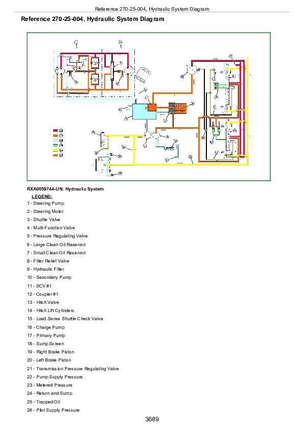
Reference 270-25-004, Hydraulic System Diagram
Section 290: OPERATOR STATION
Group 05: Preliminary Checks
Reference 290-05-001, Airflow Preliminary Check
Group 10: Operational Checks
Specifications
Reference 290-10-001, Air Conditioning Operational Checks (Standard)
Reference 290-10-002, Heating System Operational Checks (Standard)
Reference 290-10-003, CLIMATRAK CLIMATRAK is a trademark of Deere & Company (ATC) Operational Check (-902000)
Reference 290-10-005, CLIMATRAK CLIMATRAK is a trademark of Deere & Company (ATC) Operational Check (902001-)
Group 15: Tests And Adjustments
Essential Tools
Service Equipment and Tools
Specifications
Reference 290-15-001, Install Test Equipment
Reference 290-15-002, Isolate Circulation Blower Motor Circuit Malfunctions (Standard)
Reference 290-15-003, Isolate Pressurizer Blower Motor Circuit Malfunction (Standard)
Reference 290-15-004, Static Pressure Test (Standard)
Reference 290-15-005, Isolate Compressor Clutch Circuit Malfunction (Standard)
Reference 290-15-006, Deicing Switch Test (Standard)
Reference 290-15-007, Dual Pressure Switch (Low Side) Test
Reference 290-15-008, Dual Pressure Switch (High Side) Test
Reference 290-15-009, A/C System Testing (Standard)
Reference 290-15-010, CLIMATRAK CLIMATRAK is a trademark of Deere & Company (ATC) Light Code Tests (-902000)
Reference 290-15-011, CLIMATRAK CLIMATRAK is a trademark of Deere & Company (ATC) System Testing (-902000)
Reference 290-15-012, CLIMATRAK CLIMATRAK is a trademark of Deere & Company (ATC) Calibration Procedure (-902000)
Reference 290-15-021, CLIMATRAK CLIMATRAK is a trademark of Deere & Company (ATC) Recall, Record and Clear Codes (902001-)
Reference 290-15-022, CLIMATRAK CLIMATRAK is a trademark of Deere & Company (ATC) Calibration Procedure (902001-)
Reference 290-15-023, CLIMATRAK CLIMATRAK is a trademark of Deere & Company (ATC) Pressurizer Blower Test (902001-)
Reference 290-15-024, CLIMATRAK CLIMATRAK is a trademark of Deere & Company (ATC) Circulation Blower Test (902001-)
Reference 290-15-025, CLIMATRAK CLIMATRAK is a trademark of Deere & Company (ATC) System Static Pressure Test (902001-)
Reference 290-15-026, CLIMATRAK CLIMATRAK is a trademark of Deere & Company (ATC) Compressor Clutch Engagement Test (902001-)
Reference 290-15-028, CLIMATRAK CLIMATRAK is a trademark of Deere & Company (ATC) System Pressure Test (902001-)
Reference 290-15-029, CLIMATRAK CLIMATRAK is a trademark of Deere & Company (ATC) Compressor Clutch Cycling Test (902001-)
Reference 290-15-030, CLIMATRAK CLIMATRAK is a trademark of Deere & Company (ATC) A/C System Temperature Sensor Test (902001-)
Reference 290-15-031, CLIMATRAK CLIMATRAK is a trademark of Deere & Company (ATC) Temperature Drop Test (902001-)
Reference 290-15-032, CLIMATRAK CLIMATRAK is a trademark of Deere & Company (ATC) Water Valve Test (902001-)
Reference 290-15-033, CLIMATRAK CLIMATRAK is a trademark of Deere & Company (ATC) Air Flow Mode Control Test (902001-)
Reference 290-15-034, Remove Moisture From A/C System - CLIMATRAKCLIMATRAK is a trademark of Deere & Company (ATC) (902001-)
Group 20: Theory Of Operation
Reference 290-20-001, Air Conditioning Theory (Standard)
Reference 290-20-002, Air Seat Theory
Reference 290-20-003, Display Units Theory
Reference 290-20-004, Windshield Wiper / Washer Theory
Reference 290-20-005, Warning Horn Theory
Reference 290-20-006 CLIMATRAK CLIMATRAK is a trademark of Deere & Company (ATC) Theory (-902000)
Reference 290-20-007, Cab Air Circulation Theory (Standard)
Reference 290-20-008 CLIMATRAK CLIMATRAK is a trademark of Deere & Company (ATC) Theory of Operation (902001-)
Reference 290-20-009, Power Mirror Circuit Theory of Operation
Section 299: TOOLS
Group 10: Fabricated Tools
DFRW2-Needle Valve Test Hose Assembly
DFRW26-Test Lead For Automotive-Style Fuses
DFRW51-Electronic Circuit Load Tester
DFRW60 Through DFRW66-Extension and Tap-Out Harnesses
DFRW83-Nozzle Assembly
DFRW123-Steering Motor Bypass Hose
DFRW124-Engine Shut-Off Lead
DFRW126-Tap-Out Harness
DFRW129-Steering Motor Sensor Gage
DFRW130-Relay Circuit Test Lead
DFRW142-Water Valve Test Lead
DFRW167-CLIMATRAK CLIMATRAK is a trademark of Deere & Company (ATC) Water Valve Test Harness (902001-)
DFRW181, Test Hose Kit
Group 15: Test Kits
Reference 299-15-001 Test Kits
John Deere Tracks Tractors 8120T, 8220T, 8320T, 8420T, 8520T Diagnosis and Tests Service Technical Manual (TM1981)


