John Deere Tractors 5045E, 5055E, 5065E, 5075E Repair Service Manual (TM901519)
Catalog:
Model:
Complete Repair Service Technical Manual for John Deere Tractors 5045E, 5055E, 5065E & 5075E (FT4) North America, with all the workshop information to maintain, repair, and service like professional mechanics.
John Deere Tractors 5045E, 5055E, 5065E & 5075E (FT4) workshop technical manual (repair) includes:
* Numbered table of contents easy to use so that you can find the information you need fast.
* Detailed sub-steps expand on repair procedure information
* Numbered instructions guide you through every repair procedure step by step.
* Notes, cautions and warnings throughout each chapter pinpoint critical information.
* Bold figure number help you quickly match illustrations with instructions.
* Detailed illustrations, drawings and photos guide you through every procedure.
* Enlarged inset helps you identify and examine parts in detail.
TM901519 English - 5045E, 5055E, 5065E and 5075E (FT4) Tractors Repair Technical Manual Technical Manual.pdf
tm901528 French - Manuel technique de remise en état, tracteurs 5045E, 5055E, 5065E et 5075E (FT4).pdf
Total Pages: 954 pages
File Format: PDF (bookmarked, ToC, Searchable, Printable)
Language: English French
MAIN SECTIONS
Foreword
General Information
Safety
General Specifications (9x3 TSS Transmission)
General Specifications (12x12 PR Transmission)
Fuel and Lubricants
Serial Number Locations
Features and Accessories
Engine Repair
Engine
Cooling System
Fuel, Air Intake and Exhaust Systems
Fuel System
Air Intake System
Exhaust System
Electrical Repair
Battery, Starter and Alternator
Electrical System Components
Wiring Harness
Power Train Repair (12x12 PR Transmission)
Clutch Housing
Clutch Assembly
Transmission
Rear PTO
Differential
Final Drives
Mechanical Front Wheel Drive
Power Train Repair (9x3 TSS Transmission)
Clutch Housing
Clutch Assembly
Transmission
Rear PTO
Differential
Final Drives
Mechanical Front Wheel Drive
Steering and Brake Repair
Steering Repair
Brake Repair
Hydraulic Repair
Hydraulic Pump and Filter
JD Rockshaft
EATON Selective Control Valve (SCV)
Mid Mount Selective Control Valve (SCV)
Miscellaneous Repair
Front Axle
Wheels
3-Point Hitch
Hood
Operator Station Repair (OOS)
Seat and Support
Center Console
Roll-GardROLL-GARD is a trademark of Deere & Company.
Operator Platform
Fenders
Canopy (If Equipped)
Operator Station Repair (Cab)
Seat and Support
Control Console
Cab Components
Air Conditioning System
Heating System
TABLE OF CONTENTS
Section 10: General Information................18
Group 05: Safety................18
Recognize Safety Information................22
Understand Signal Words................23
Follow Safety Instructions................24
Handle Fluids Safely—Avoid Fires................25
Prevent Battery Explosions................26
Prepare for Emergencies................27
Prevent Acid Burns................28
Service Cooling System Safely................30
Avoid High-Pressure Fluids................31
Park Machine Safely................32
Support Machine Properly................33
Wear Protective Clothing................34
Work in Clean Area................35
Service Machines Safely................36
Work In Ventilated Area................37
Illuminate Work Area Safely................38
Replace Safety Signs................39
Use Proper Lifting Equipment................40
Service Tires Safely................41
Avoid Harmful Asbestos Dust................42
Avoid Heating Near Pressurized Fluid Lines................43
Remove Paint Before Welding or Heating................44
Use Proper Tools................45
Dispose of Waste Properly................46
Live With Safety................47
Group 10: General Specifications (9x3 TSS Transmission)................18
Machine Specifications................900
Repair Specifications................900
Ground Speed Estimates — Sync Shuttle Transmission................57
Service Recommendations for O-Ring Boss Fittings................80
Service Recommendations for Flat Face O-Ring Seal Fittings................82
Metric Bolt and Cap Screw Torque Values................84
Unified Inch Bolt and Cap Screw Torque Values................85
Glossary of Terms................87
Group 11: General Specifications (12x12 PR Transmission)................19
Machine Specifications................900
Repair Specifications................900
Ground Speed Estimates — PowrReverser PowrReverser is a trademark of Deere & Company Transmission................19
Service Recommendations for O-Ring Boss Fittings................80
Service Recommendations for Flat Face O-Ring Seal Fittings................82
Metric Bolt and Cap Screw Torque Values................84
Unified Inch Bolt and Cap Screw Torque Values................85
Glossary of Terms................87
Group 15: Fuel and Lubricants................19
Diesel Fuel................93
Handling and Storing Diesel Fuel................95
Lubricity of Diesel Fuel................96
Testing Diesel Fuel................97
BioDiesel Fuel................98
Do Not Use Galvanized Containers................100
Fill Fuel Tank................101
Diesel Engine Break-In Oil — Non-Emissions Certified and Certified Tier 1, Tier 2, Tier 3, Stage I, Stage II, and Stage III................103
Diesel Engine Oil — Interim Tier 4, Final Tier 4, Stage IIIB, and Stage IV................105
Oil Filters................107
Diesel Engine Coolant (engine with wet sleeve cylinder liners)................108
Operating in Warm Temperature Climates................110
Water Quality for Mixing with Coolant Concentrate................111
Testing Coolant Freeze Point................112
Transmission and Hydraulic Oil................114
Additional Information About Diesel Engine Coolants and John Deere LIQUID COOLANT CONDITIONER................116
Use Correct Transmission/Hydraulic Filter Element................118
Gear Oil................119
Grease................120
Mixing of Lubricants................121
Alternative and Synthetic Lubricants................122
Lubricant Storage................123
Group 20: Serial Number Locations................20
Serial Numbers................125
Product Identification Number................126
Record Engine Serial Number................127
Fuel Injection Pump Serial Number................128
Alternator Serial Number Location................129
Power Steering Valve Serial Number Location................130
Starter Serial Number Location................131
Transaxle Serial Number Location (12x12 PR Transmission)................132
Record Front Axle (2-WD) Serial Number................133
Record Mechanical Front Wheel Drive (MFWD) Serial Number................134
Group 25: Features and Accessories................136
Features and Accessories................136
Standard Features................137
Factory Installed Optional Equipment................139
Field Installed Optional Kits and Accessories................140
Section 20: Engine Repair................141
Group 05: Engine................141
Service Equipment and Tools................898
Specifications................900
John Deere Engine Repair—Use CTM................145
Remove Engine — Cab................146
Remove Engine — OOS................154
Install Engine — Cab................161
Install Engine — OOS................169
Remove and Install Rocker Arm Cover................176
Group 30: Cooling System................141
Special or Essential Tools................895
Specifications................900
Torques for Hardware................180
Remove and Inspect Radiator (OOS)................181
Remove and Inspect Radiator (Cab)................186
Water Pump — Exploded View................191
Cooling System Repair—Use CTM................192
Section 30: Fuel, Air Intake and Exhaust Systems................193
Group 05: Fuel System................193
Special or Essential Tools................895
Injection Pump, Nozzle and Governor Repair—Use CTM................202
Remove, Inspect and Install Fuel Tank (OOS)................203
Remove, Inspect and Install Fuel Tank (Cab)................206
Remove, Inspect and Install Fuel Cooler................210
Group 10: Air Intake System................193
Remove, Inspect, and Install Air Cleaner Elements................214
Remove, Inspect and Install Air Cleaner Assembly................217
Check Air Inlet Pipe with Turbocharger................219
Remove and Install Turbocharger................220
Turbocharger Repair................222
Group 15: Exhaust System................193
Other Material................899
Specifications................900
Service Exhaust System................226
Section 40: Electrical Repair................233
Group 05: Battery, Starter and Alternator................233
Starter Repair—Use CTM................237
Remove and Install Battery (OOS)................238
Remove and Install Battery (Cab)................240
Remove and Install Starter................242
Replace Alternator/Regulator................243
Group 10: Electrical System Components................233
Essential or Recommended Tools................245
Other Material................899
Specifications................900
Servicing Electronic Control Units................248
Keep Electronic Control Unit Connectors Clean................249
Repair Engine Electrical System Components—Use CTM................250
Replace Air Filter Restriction Sensor................251
Replace Coolant Temperature Sensor................252
Replace Engine Speed Sensor................253
Replace Engine Oil Pressure Sensor................254
Replace Key Switch (OOS)................255
Replace Key Switch (CAB)................256
Replace Light Switch (OOS)................257
Replace Light Switch (CAB)................259
Replace Turn Signal Switch (OOS)................261
Remove and Replace Turn Signal Switch (Cab)................263
Replace Wiper Control Switch................264
Remove And Install Wiper Motor................265
Remove and Install Instrument Panel................750
Remove and Replace Forward, Neutral, Reverse Lever (If Equipped)................270
Remove and Install Acceleration Potentiometer (Shuttle Control) (If Equipped)................272
Replace Horn Switch (If Equipped)................273
Replace Starter Relay................274
Replace Hand Throttle Position Sensor................275
Replace Foot Throttle Position Sensor................277
Replace Rear PTO ON/OFF Switch (OOS)................282
Replace Rear PTO ON/OFF Switch (Cab)................284
Replace Electro-Hydraulic Control (EHC) Unit—OOS................285
Replace Electro-Hydraulic Control (EHC) Unit—Cab................287
Replace Engine Control Unit (ECU) (2.9 L)................288
Replace Enable Proportional Solenoid Valve—PR Transmission................290
Replace Transmission Reverse Solenoid Valve—PR Transmission................292
Replace Transmission Forward Solenoid Valve—PR Transmission................293
Replace Clutch Pedal Position Sensor (PR Transmission)................294
Remove and Install Rear PTO Switch (TSS Transmission)—OOS................297
Remove and Install Rear PTO Switch (TSS Transmission)—Cab................304
Replace Neutral Start Switch................306
Replace Seat Switch (OOS)................307
Replace Seat Switch (Cab)................309
Replace Fuel Level Sender (OOS)................310
Replace Fuel Level Sender (Cab)................311
Group 15: Wiring Harness................234
Service Equipment and Tools................898
Essential Tools................895
Remove Connector Body from Blade Terminals................316
Replace WEATHER PACK WEATHER PACK is a trademark of Packard Electric. Connector................234
Install WEATHER PACK WEATHER PACK is a trademark of Packard Electric. Contact................234
Repair (Pull Type) METRI-PACK™ Connectors................321
Repair (Push Type) METRI-PACK™ Connectors................323
Exploded View—CINCH Flexbox Connectors................326
CINCH™ Flexbox Connectors................327
Repair DEUTSCH™ Connectors................331
Replace Positive Battery Cable (OOS)................335
Replace Negative Battery Cable (OOS)................336
Replace Battery Positive Cable (Cab)................337
Replace Engine Power Cable................338
Replace Hood Wiring Harness................340
Replace Beacon Lamp Wiring Harness (If Equipped)................341
Replace Left Rear Work Light Harness (OOS)................342
Replace Right Rear Work Light Harness (OOS)................344
Replace Front Console Wiring Harness—OOS (9x3 TSS Transmission)................346
Replace Front Console Wiring Harness—OOS (12x12 PowrReverser™ Transmission)................348
Replace Front Console Wiring Harness—Cab (9x3 TSS Transmission)................350
Replace Front Console Wiring Harness—Cab (12x12 PowrReverser PowrReverser is a trademark of Deere & Company Transmission)................235
Replace Transmission Wiring Harness—OOS (12x12 PowrReverser PowrReverser is a trademark of Deere & Company Transmission)................235
Replace Transmission Wiring Harness—OOS (9x3 TSS Transmission)................357
Replace Engine Harness................359
Replace Cab Power Harness................360
Replace Rear Wiring Harness—Cab (9x3 TSS Transmission)................362
Replace Rear Wiring Harness—Cab (12x12 PowrReverser™ Transmission)................365
Replace Transmission Harness—Cab (12x12 PowrReverser PowrReverser is a trademark of Deere & Company Transmission)................235
Replace Roof Harness—Cab................370
Replace Exhaust Filter Harness................372
Replace Injector Harness................374
Section 50: Power Train Repair (12x12 PR Transmission)................375
Group 05: Clutch Housing................375
John Deere Transmission Repair — Use CTM................488
Specifications................900
Separate Engine from Clutch Housing (PR)................380
Install Engine to Clutch Housing (PR)................388
Remove, Inspect, and Repair Clutch Pedal and Linkage (PR)................396
Group 10: Clutch Assembly................375
Specifications................900
John Deere Transmission Repair — Use CTM................488
Group 15: Transmission................375
Other Material................899
Specifications................900
John Deere Transmission Repair — Use CTM................488
Inspect and Repair Gear Shift Lever................475
Inspect and Repair Range Shift Lever................477
Group 21: Rear PTO................375
Other Material................899
Specifications................900
John Deere Transmission Repair — Use CTM................488
Group 26: Differential................375
Essential Tools................895
Service Equipment and Tools................898
Other Material................899
Specifications................900
Service Parts Kits................614
John Deere Transmission Repair — Use CTM................488
Group 30: Final Drives................375
Service Equipment and Tools................898
Other Material................899
Specifications................900
John Deere Transmission Repair — Use CTM................488
Group 35: Mechanical Front Wheel Drive................376
Mechanical Front Wheel Drive – If Equipped—Summary of References................506
Service Equipment and Tools................898
Essential Tools................895
Other Material................899
Specifications................900
MFWD Axle Repair — Use CTM................434
MFWD Dropbox Repair—Use CTM................435
Remove, Inspect and Install MFWD Drive Shaft(PR)................436
Remove and Install MFWD Axle Housing Assembly(PR)................437
Remove, Inspect and Install MFWD Axle Supports (Without Paddy Seal)(PR)................439
Section 51: Power Train Repair (9x3 TSS Transmission)................441
Group 05: Clutch Housing................441
John Deere Transmission Repair — Use CTM................488
Service Equipment and Tools................898
Other Material................899
Essential Tools................895
Specification................698
Separate Engine from Clutch Housing (TSS)................449
Install Engine to Clutch Housing (TSS)................457
Inspect and Repair Clutch Pedal and Linkage (TSS)................465
Inspect and Repair Clutch Pedal and Linkage (TSS- Cab)................467
Group 10: Clutch Assembly................441
Specification................698
John Deere Transmission Repair — Use CTM................488
Group 15: Transmission................441
Specifications................900
John Deere Transmission Repair — Use CTM................488
Inspect and Repair Gear Shift Lever................475
Inspect and Repair Range Shift Lever................477
Group 21: Rear PTO................441
Other Material................899
Specifications................900
John Deere Transmission Repair — Use CTM................488
Remove, Inspect and Install Rear PTO Lever and Linkage................483
Remove, Inspect and Install Rear PTO Lever and Linkage — (OOS)................485
Group 26: Differential................441
John Deere Transmission Repair — Use CTM................488
Group 30: Final Drives................441
Service Equipment and Tools................898
Other Material................899
Specifications................900
Remove and Install Final Drive Assembly................493
Remove and Inspect Planetary Drive Assembly................495
Install Planetary Drive Assembly................498
Remove, Inspect, and Install Axle Shaft Assembly................501
Group 35: Mechanical Front Wheel Drive................442
Mechanical Front Wheel Drive – If Equipped—Summary of References................506
Service Equipment and Tools................898
Essential Tools................895
Other Material................899
Specifications................900
MFWD Axle Repair—Use CTM................514
Inspect and Repair MFWD Lever and Linkage................515
Remove and Install MFWD Drop Gearbox................517
Disassemble and Inspect MFWD Drop Gear box................519
MFWD Drop Gearbox Cross Section................522
Assemble MFWD Drop Gearbox................524
Remove, Inspect and Install MFWD Drive Shaft................530
Remove and Install MFWD Axle Housing Assembly................531
Remove, Inspect and Install MFWD Axle Supports (Without Paddy Seal)................533
Section 60: Steering and Brake Repair................535
Group 05: Steering Repair................535
Other Material................899
Specifications................900
Service Parts Kits................614
Remove and Install Steering Wheel................540
Remove and Install Tilt/Telescoping Steering Column................542
Remove and Install Steering Column and Valve................544
Disassemble and Inspect Steering Valve - Sauer Danfoss................546
Assemble Steering Valve - Sauer Danfoss................550
Disassemble and Inspect Steering Valve - Eaton................555
Assemble Steering Valve - Eaton................560
Remove and Install Steering Cylinder—2WD Axle................566
Disassemble, Inspect, and Assemble Steering Cylinder—2WD Axle................570
Remove, Inspect and Install Tie Rod Assembly—2WD Axle................572
Remove and Install Steering Cylinder— MFWD Axle................575
Disassemble, Inspect, and Assemble Steering Cylinder—MFWD Axle................578
Remove, Inspect and Install Tie Rod Assembly—MFWD Axle................579
Inspect and Replace Steering Hydraulic Lines................582
Group 10: Brake Repair................535
Service Equipment and Tools................898
Other Material................899
Specifications................900
Remove and Install Brake Valve and Pedals................588
Disassemble and Inspect Brake Pedals and Valve................590
Brake Valve Cross Section................593
Assemble Brake Valve................595
Remove and Inspect Brakes................598
Install Brakes................600
Bleed Brakes................603
Adjust Brake Retractors................604
Inspect and Replace Brake Hydraulic Lines (Cab)................605
Inspect and Replace Brake Hydraulic Lines (OOS)................607
Section 70: Hydraulic Repair................609
Group 05: Hydraulic Pump and Filter................609
Essential Tools................895
Specifications................900
Service Parts Kits................614
Remove, Inspect, and Install Hydraulic Oil Pick-Up Screen................615
Remove and Install Hydraulic Pump................617
Remove Hydraulic Pump External Components................619
Disassemble and Inspect Hydraulic Pump................620
Assemble Hydraulic Pump................623
Install Hydraulic Pump External Components................625
Remove and Install Hydraulic Oil Filter/Manifold................627
Inspect and Replace Hydraulic Supply and Suction/Return Lines................628
Group 15: JD Rockshaft................609
Other Material................899
Specifications................900
Inspect and Repair Rockshaft Control Lever Assembly................633
Inspect and Repair Rockshaft Control Linkage................638
Inspect and Repair Draft Sensing Support Assembly................642
Replace Main Relief Valve................644
Replace Rockshaft Surge Relief Valve................646
Replace Rockshaft Control Valve................648
Remove and Install Rockshaft Case................652
Remove, Inspect, and Install Rockshaft Piston and Cylinder................655
Group 25: EATON Selective Control Valve (SCV)................609
Install Single Selective Control Valve (SCV)................661
Install Rear Coupler Bracket................664
Install Hydraulic Hoses................675
Install Second Selective Control Valve (SCV)................670
Assemble Rear Quick Coupler................673
Install Hydraulic Hoses................675
Group 30: Mid Mount Selective Control Valve (SCV)................609
Service Parts Kit................680
Other Material................899
Specifications................900
Remove and Install Mid Mount Control Valve................683
Remove, Inspect and Install Joystick and Cables—Mid Mount Valve................686
Disassemble, Inspect, and Assemble Joystick—Mid Mount Coupler................688
Disassemble, Inspect and Assemble Mid Mount Control Valve................690
Inspect and Replace Hydraulic Hoses—Mid Mount Coupler................694
Section 80: Miscellaneous Repair................696
Group 05: Front Axle................696
Specification................698
Remove and Install Front Axle—2WD................699
Remove and Install Front Axle — MFWD................702
Inspect and Replace Pivot Pin and Bushings—2WD Axle................706
Remove and Install Spindle Assembly—2WD................707
Inspect and Replace Spindle Shaft Bushings—2WD Axle................709
Group 10: Wheels................696
Specifications................900
Remove and Install Front or Rear Wheels................712
Inspect and Replace Front Wheel Bearings................713
Tighten Bolts—Rear Axle (M-20 Stud)................715
Tighten Nuts—Front Axle (MFWD)................716
Tighten Cap Screws—Front Axle (2WD)................717
Group 15: 3-Point Hitch................696
Specifications................900
Inspect and Repair Fixed Draft Links................720
Inspect and Repair Telescopic Draft Links (If Equipped)................721
Inspect and Repair Lift Link (If Equipped)................724
Inspect and Repair Lift Link (If Equipped)................724
Inspect and Repair Adjustable Lift Link (If Equipped)................728
Inspect and Repair Adjustable Lift Link (If Equipped)................728
Inspect and Repair Center Link................730
Group 25: Hood................696
Remove and Install Hood................733
Section 90: Operator Station Repair (OOS)................734
Group 05: Seat and Support................734
Remove and Install Seat and Support (OOS)................736
Disassemble, Inspect and Assemble Seat and Seat Switch................737
Group 06: Center Console................734
Remove and Install Cowl Cover (OOS)................741
Remove and Install Right-Side Control Console................743
Remove and Install Left-Side Control Console................746
Remove and Install Instrument Panel................750
Group 10: Roll-Gard™................734
Specifications................900
Remove and Install Roll-Gard™................754
ROPS Serial Number................758
Group 15: Operator Platform................734
Specifications................900
Remove Right-Side Platform and Step................761
Remove and Install Left-Side Platform and Handrail................769
Group 20: Fenders................734
Remove and Install Fenders................776
Group 25: Canopy (If Equipped)................734
Specifications................900
Remove and Install Canopy................781
Section 91: Operator Station Repair (Cab)................783
Group 05: Seat and Support................783
Remove and Install Seat and Support (Cab)................787
Group 10: Control Console................783
Specifications................900
Remove and Install Right-Side Control Console—Cab................790
Remove and Install Left-Side Control Console—Cab................792
Remove and Install Cowl Cover (Cab)................794
Remove and Install Front Control Console................795
Group 20: Cab Components................783
Essential Tools................895
Service Equipment and Tools................898
Other Material................899
Specifications................900
Remove, Inspect, and Install Cab Interior Recirculating Air Filters................802
Remove, Inspect, and Install Exterior Cab Intake Air Filter................804
Remove and Install Headliner................806
Remove and Install Left-Side Upholstery................809
Remove and Install Right-Side Upholstery................811
Remove and Install Windshield................813
Remove and Install Front Lower Windows................815
Remove and Install Rear Lower Window................817
Remove and Install Rear Upper Window................818
Remove and Install Side Windows................819
Remove and Install Cab Doors................821
Remove and Install Inner Roof for Air Conditioning Housing Repair................837
Remove and Install Inner Roof for Air Conditioning Housing Repair................837
Remove Cab................860
Remove Cab................860
Install Cab................882
Install Cab................882
Group 30: Air Conditioning System................783
Essential Tools................895
Service Equipment and Tools................898
Other Material................899
Specifications................900
Adjust A/C Temperature Control Switch................901
Recover/Recycle Air Conditioning Refrigerant................903
Replace Air Conditioning Receiver/Dryer................904
Remove, Inspect, and Install Air Conditioning Condenser................906
Remove, Inspect, and Install Air Conditioning Compressor................910
Test Volumetric Efficiency of Compressor................912
Test Compressor Shaft Seal Leakage................914
Disassemble and Assemble Compressor Clutch................916
Disassemble, Inspect, and Assemble Compressor................918
Check Compressor Clutch Hub Clearance................922
Inspect Compressor Manifold................923
Remove, Inspect, and Install Compressor Relief Valve................924
Remove Blower Motors................925
Remove Evaporator/Heater Core................926
Leak Test Evaporator/Heater Core................928
Install Evaporator/Heater Core................929
Service Expansion Valve................931
Expansion Valve Bench Test................932
Refrigerant Oil Information................934
Check Compressor Oil Charge................935
Determine Correct Refrigerant Oil Charge................936
Add Refrigerant Oil to System................938
System Information................939
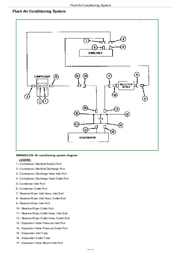
Flush Air Conditioning System................940
Evacuate Air Conditioning System................945
Charge Air Conditioning System................946
Group 35: Heating System................784
Adjust Heater Temperature Control Cable................949
Replace Heater Temperature Control Cable................951
Remove Heater Control Valve................954
Leak Test Heater Control Valve................955
Install Heater Control Valve................956
John Deere Tractors 5045E, 5055E, 5065E, 5075E Repair Service Manual (TM901519)


