TM101819 - Operation & Tests Technical Manual for John Deere Combines Models 9570 STS, 9670 STS, 9770 STS, 9870 STS
Catalog:
Model:
Complete Operation and Tests manual with electrical wiring diagrams for John Deere Combines 9570 STS, 9670 STS, 9770 STS, 9870 STS, with technicial information to maintain, diagnose, and service like professional mechanics.
John Deere Combines 9570 STS, 9670 STS, 9770 STS, 9870 STS Diagnostic manual includes:
* Numbered table of contents easy to use so that you can find the information you need fast.
* Detailed sub-steps expand on repair procedure information
* Numbered instructions guide you through every repair procedure step by step.
* Troubleshooting and electrical service procedures are combined with detailed wiring diagrams for ease of use.
* Notes, cautions and warnings throughout each chapter pinpoint critical information.
* Bold figure number help you quickly match illustrations with instructions.
* Detailed illustrations, drawings and photos guide you through every procedure.
* Enlarged inset helps you identify and examine parts in detail.
TM101819 English - John Deere Combines 9570 STS, 9670 STS, 9770 STS and 9870 STS with Flex Platform Models 630R, 615F, 618F, 620F, 622F, 625F, 630F, 635F Technical Manual (Operation and Tests).PDF
tm101814 Chinese - 9570 STS, 9670 STS, 9770 STS, 9870 STS Combines Diagnostic Technical Manual
tm101854 Portuguese - Manual Técnico de Diagnóstico das Colheitadeiras 9570 STS, 9670 STS, 9770 STS e 9870 STS
tm101859 Russian - 9570 STS, 9670 STS, 9770 STS, 9870 STS Combines Diagnostic Technical Manual
tm100219 English - 600 Series Corn Heads Diagnostic Technical Manual (Diagnosis and Tests).pdf
tm2166 English - 600 Series Rigid and Flex Platforms (Diagnosis and Tests)
tm9038 Russian - Жecткие и гибкие плaтфopмы cepии 600
tm2168 English - 90 Series Corn Heads (705101 - ) Diagnosis and Tests
tm2174 English - 925D, 930D and 936D (705101 - ) DraperPlatforms Diagnosis and Tests
tm2316 English - 615P Belt Pickup Diagnosis and Tests
tm9044 Russian - Диaгнocтикa и тecтиpoвaние пoлoтеннoгo пoдбopщ
Total Pages: 10,224 pages
File Format: PDF (bookmarked, ToC, Searchable, Printable)
Language: English
MAIN SECTIONS
Foreword
General
Safety
Combine and Component Identification
General Specifications
Diagnostic and Testing Procedures
Diagnostic Trouble Codes
Accessing Diagnostic Codes and Addresses
ADU - Armrest Display Unit
CAB - Control Unit CAB and Cab Power Module Diagnostic Trouble Codes
CDU - Cornerpost Display Unit
ECU - Control Unit ECU Diagnostic Trouble Codes
GreenStar Display Warning Messages and Fault Codes
GreenStar KeyCard and Data Storage Card Warning Messages
GreenStar Mobile Processor Warning Messages
HARVEST DOC Warning Messages
HMM - Harvest Moisture Meter
LC1 - Control Unit LC1 and Left Power Module 1 Diagnostic Trouble Codes
LC2 - Control Unit LC2 and Left Power Module 2 Diagnostic Trouble Codes
PTP - Start-Up Codes
PTP - Control Unit PTP Diagnostic Trouble Codes
RCU - Control Unit RCU and Right Power Module Diagnostic Trouble Codes
SFC - Control Unit SFC Diagnostic Trouble Codes
SSU - Control Unit SSU Diagnostic Trouble Codes
SSU - Last Exit Codes
LCR - StarFire Receiver 300 Diagnostic Trouble Codes
StarFire Receiver (iTC and 3000) Diagnostic Trouble Codes
StarFire Receiver Warning Messages
Terrain Compensation Module Diagnostics Trouble Codes
VCM - Control Unit VCM Diagnostic Trouble Codes
Guidance - Universal Row Guidance Diagnostic Trouble Codes
VTi - GreenStar Display 2100/2600
Observable Symptoms
Engine System
Air Intake and Cooling Systems
Electrical System
Power Train System
Four Wheel Drive System
Brake System
Hydraulic System
Main Gearcase System
Steering System
Heating, Ventilating and Air Conditioning System
Separator System
Engine System
General Information
Test Procedures and Adjustments
Engine Type Identification
Engine Diagnostics - Type A
Engine Diagnostics - Type B
Engine Diagnostics - Type C
Component Identification and Location
Air Intake and Cooling System
General Information
Test Procedures and Adjustments
Air Intake System Diagnostics
Cooling Package Type Identification
Cooling Package Diagnostics - Type A
Cooling Package Diagnostics - Type B
Component Identification and Location
Electrical System
How To Use This Diagnostic Information
Accessing Diagnostic Trouble Codes and Addresses
Diagnostic Addresses by Controller
Machine Setting Addresses
Diagnostic Trouble Codes, Warning Messages and Fault Codes
Calibration Procedures
Active Header Height Control Type Identification
Active Header Height Diagnostics - Type A
Active Header Height Diagnostics - Type B
Active Header Height Diagnostics - Type C
Active Header Height Diagnostics - Type D
Active Header Height Diagnostics - Type E
Active Header Height Diagnostics - Type F
Active Header Height Diagnostics - Type G
Active Header Height Diagnostics - Type H
Air Seat Diagnostics
Alternator and Battery Diagnostics
Area Counter Diagnostics
Armrest Display Unit Overall Diagnostics
Auxiliary Power Strip Outlet Diagnostics
Backup Alarm Type Identification
Backup Alarm Diagnostics - Type A
Backup Alarm Diagnostics - Type B
CAN Bus Diagnostics
Chassis Tilt Diagnostics
Chopper Raise/Lower Type Identification
Chopper Raise/Lower Diagnostics - Type A
Chopper Raise/Lower Diagnostics - Type B
Chopper Speed Sensor Diagnostics
Chopper Vane Angle Diagnostics
Clean Grain Elevator Speed Sensor Diagnostics
Cleaning Fan Speed Adjust Diagnostics
Cleaning Fan Speed Display Diagnostics
Control Unit CAB/CPM Overall Diagnostics
Control Unit CDU Overall Diagnostics
Control Unit ECU Overall Type Identification
Control Unit ECU Overall Diagnostics - Type A
Control Unit ECU Overall Diagnostics - Type B
Control Unit LC1/LPM1 Overall Diagnostics
Control Unit LC2/LPM2 Overall Diagnostics
Control Unit PTP Overall Diagnostics
Control Unit RCU/RPM Overall Diagnostics
Control Unit SFC Overall Diagnostics
Control Unit SSU Overall Diagnostics
Control Unit VCM Overall Diagnostics
Conveyor Auger Speed Sensor Diagnostics
Corn Head Chopper Speed Sensor Diagnostics
Cutterbar Pressure Adjust Diagnostics
Deck Plate Adjust Type Identification
Deck Plate Adjust Diagnostics - Type A
Deck Plate Adjust Diagnostics - Type B
Deck Plate Display Diagnostics
Deck Plate Resume Diagnostics
Discharge Beater Speed Sensor Diagnostics
Draper Belt Slippage Detection System Diagnostics
Draper Cutterbar Tilt Adjust Diagnostics
Draper Frame Float Type Identification
Draper Frame Float Adjust Diagnostics - Type A
Draper Frame Float Adjust Diagnostics - Type B
Draper Speed Adjust Type Identification
Draper Speed Adjust Diagnostics - Type A
Draper Speed Adjust Diagnostics - Type B
Electric Fuel Pump Type Identification
Electric Fuel Pump Diagnostics - Type A
Electric Fuel Pump Diagnostics - Type B
Electric Fuel Pump Diagnostics - Type C
Engine Air Filter Sensor Diagnostics
Engine and Fuel Control Type Identification
Engine and Fuel Control Diagnostics - Type A
Engine and Fuel Control Diagnostics - Type B
Engine and Fuel Control Diagnostics - Type C
Engine Coolant Temperature Sensor Diagnostics
Engine Oil Pressure Sensor Diagnostics
Feed Accelerator Speed Sensor Diagnostics
Feeder House Filter Switch Type Identification
Feeder House Filter Switch Diagnostics - Type A
Feeder House Filter Switch Diagnostics - Type B
Feeder House Pressure Sensor Diagnostics
Feeder House Reverse Diagnostics
Feeder House Speed Adjust Type Identification
Feeder House Speed Adjust Diagnostics - Type A
Feeder House Speed Adjust Diagnostics - Type B
Feeder House Speed Display Diagnostics
Folding Corn Head Diagnostics
Four Wheel Drive Diagnostics
Fuel Level Display Diagnostics
Glow Plug Diagnostics
Grain Level Switch Type Identification
Grain Level Switch Diagnostics - Type A
Grain Level Switch Diagnostics - Type B
Grain Loss Monitor Diagnostics
Grain Tank Cover Diagnostics
GreenStar - Data Card Type Identification
GreenStar - Data Card Diagnostics - Type A
GreenStar - Data Card Diagnostics - Type B
GreenStar - Display Type Identification
GreenStar - Display Diagnostics - Type A
GreenStar - Display Diagnostics - Type B
GreenStar - Display Diagnostics - Type C
GreenStar - Documentation Type Identification
GreenStar - Documentation Diagnostics - Type A
GreenStar - Documentation Diagnostics - Type B
GreenStar - Mobile Processor Diagnostics
GreenStar - RTK Type Identification
GreenStar - RTK Diagnostics - Type A
GreenStar - RTK Diagnostics - Type B
GreenStar - RTK Diagnostics - Type C
GreenStar - StarFire Receiver Type Identification
GreenStar - StarFire Receiver Diagnostics - Type A
GreenStar - StarFire Receiver Diagnostics - Type B
GreenStar - StarFire Receiver Diagnostics - Type C
GreenStar - StarFire Receiver Diagnostics - Type D
GreenStar - StarFire Receiver Diagnostics - Type E
GreenStar - StarFire Receiver Diagnostics - Type F
GreenStar - Steering - Auto Type Identification
GreenStar - Steering - Auto Diagnostics - Type A
GreenStar - Steering - Auto Diagnostics - Type B
GreenStar - Steering - Auto Diagnostics - Type C
GreenStar - Steering - Auto Diagnostics - Type D
GreenStar - Steering - Auto Diagnostics - Type E
GreenStar - Steering - Manual Type Identification
GreenStar - Steering - Manual Diagnostics - Type A
GreenStar - Steering - Manual Diagnostics - Type B
Ground Speed Display Type Identification
Ground Speed Display Diagnostics - Type A
Ground Speed Display Diagnostics - Type B
Harvest Monitor Diagnostics
Header Engage Type Identification
Header Engage Diagnostics - Type A
Header Engage Diagnostics - Type B
Header Identification Diagnostics
Header Raise/Lower Diagnostics
Heating, Ventilating and Air Conditioning Diagnostics
Horn Diagnostics
Hydraulic Oil Temperature Sensor Diagnostics
Hydrostatic Charge Pressure Switch Diagnostics
Hydrostatic Drive Control Diagnostics - Automatic Feed Rate Type Identification
Hydrostatic Drive Control Diagnostics - Automatic Feed Rate - Type A
Hydrostatic Drive Control Diagnostics - Automatic Feed Rate - Type B
Hydrostatic Drive Control Diagnostics - Manual
Lateral Tilt - Automatic Diagnostics
Lateral Tilt - Display Diagnostics
Lateral Tilt - Manual Diagnostics
Lighting - Beacon Lights Diagnostics
Lighting - Brake Light Diagnostics
Lighting - Dome Light Diagnostics
Lighting - Draper Transport Diagnostics
Lighting - Engine Service Lights Diagnostics
Lighting - Field Lights Type Identification
Lighting - Field Lights Diagnostics - Type A
Lighting - Field Lights Diagnostics - Type B
Lighting - Field Lights Diagnostics - Type C
Lighting - Field Lights Diagnostics - Type D
Lighting - Gullwing Service Lights Diagnostics
Lighting - Hazard Lights Type Identification
Lighting - Hazard Lights Diagnostics - Type A
Lighting - Hazard Lights Diagnostics - Type B
Lighting - Marker Lights Type Identification
Lighting - Marker Lights Diagnostics - Type A
Lighting - Marker Lights Diagnostics - Type B
Lighting - Panel Lights Diagnostics
Lighting - Road Lights Type Identification
Lighting - Road Lights Diagnostics - Type A
Lighting - Road Lights Diagnostics - Type B
Lighting - Road Lights Diagnostics - Type C
Lighting - Shoe Service Lights Diagnostics
Lighting - Side Finder Lights Diagnostics
Lighting - Unloading Auger Light Diagnostics
Lighting - Work Lights Diagnostics
Local Link System - CAB/CPM Diagnostics
Local Link System - LC1/LPM1 Diagnostics
Local Link System - LC2/LPM2 Diagnostics
Local Link System - RCU/RPM Diagnostics
Main Gearcase Filter Switch Diagnostics
Main Gearcase Pressure Sensor Diagnostics
Main Gearcase Temperature Sensor Diagnostics
Mass Flow Sensor Diagnostics
Mirror System - Aiming Diagnostics
Mirror System - Heater Diagnostics
Moisture Sensor Diagnostics
Parking Brake Alert Type Identification
Parking Brake Alert Diagnostics
Power Distribution - Fuse Center Diagnostics
Power Distribution - Wake-up Power Diagnostics
Quick Stop Diagnostics
Radio Diagnostics
Reel Fore/Aft Adjust Type Identification
Reel Fore/Aft Adjust Diagnostics - Type A
Reel Fore/Aft Adjust Diagnostics - Type B
Reel Raise/Lower Type Identification
Reel Raise/Lower Diagnostics - Type A
Reel Raise/Lower Diagnostics - Type B
Reel Raise/Lower Diagnostics - Type C
Reel Raise/Lower Diagnostics - Type D
Reel Resume - Fore/Aft Diagnostics
Reel Resume - Raise/Lower Diagnostics
Reel Reverse Diagnostics
Reel/Belt Speed - Automatic Adjust Diagnostics
Reel/Belt Speed - Manual Adjust Diagnostics
Remote Chaffer Adjust Diagnostics - Type Identification
Remote Chaffer Adjust Diagnostics - Type A
Remote Chaffer Adjust Diagnostics - Type B
Remote Sieve Adjust Diagnostics - Type Identification
Remote Sieve Adjust Diagnostics - Type A
Remote Sieve Adjust Diagnostics - Type B
Road/Field Diagnostics
Road Speed Limit Type Identification
Road Speed Limit Diagnostics - Type A
Road Speed Limit Diagnostics - Type B
Row Guidance Type Identification
Row Guidance Diagnostics - Type A
Row Guidance Diagnostics - Type B
Separator Engage Diagnostics
Service Brake Charge Pressure Diagnostics
Shoe Leveling Diagnostics
Start Aid Diagnostics
Starter Diagnostics
Straw Spreader Speed Adjust Diagnostics
Straw Spreader Speed Sensor Diagnostics
Tailings Elevator Speed Sensor Diagnostics
Tailings Monitor Diagnostics
Threshing Clearance Adjust Diagnostics
Threshing Clearance Display Diagnostics
Threshing Speed Adjust Diagnostics
Threshing Speed Display Diagnostics
Transmission - Differential Lock Diagnostics
Transmission - Parking Brake Engage Diagnostics
Transmission - Shift Lock Diagnostics
Transmission - Speed Limit Diagnostics
Transmission - Two Range Automatic Diagnostics
Unloading Auger Engage Diagnostics
Unloading Auger Fold Diagnostics
Unloading Auger Swing Diagnostics
Windshield Washer/Wiper Diagnostics
Circuit Code Listing
Connector Information
Connector Repair Procedures
Power Train System
General Information
Test Procedures and Adjustments
Final Drive Diagnostics
Transmission Type Identification
Transmission Diagnostics - Type A
Transmission Diagnostics - Type B
Hydrostatic Drive Type Identification
Hydrostatic Drive Diagnostics - Type A
Hydrostatic Drive Diagnostics - Type B
Hydrostatic Drive Diagnostics - Type C
Component Identification and Location
Four Wheel Drive System
General Information
Test Procedures and Adjustments
Two Speed Four Wheel Drive Type Identification
Two Speed Four Wheel Drive Diagnostics - Type A
Two Speed Four Wheel Drive Diagnostics - Type B
Component Identification and Location
Brake System
General Information
Test Procedures and Adjustments
Park Brake Type Identification
Park Brake Diagnostics - Type A
Park Brake Diagnostics - Type B
Service Brakes Type Identification
Service Brakes Diagnostics - Type A
Service Brakes Diagnostics - Type B
Component Identification and Location
Hydraulic System
General Information
Test Procedures And Adjustments
Basic Hydraulic System Type ID
Basic Hydraulic System Diagnostics - Type A
Basic Hydraulic System Diagnostics - Type B
Belt Pickup Drive Type Identification
Belt Pickup Drive Diagnostics - Type A
Belt Pickup Drive Diagnostics - Type B
Belt Pickup Drive Diagnostics - Type C
Chassis Tilt Diagnostics
Cutterbar Pressure Adjust Diagnostics
Deck Plate Adjust Diagnostics - Type Identification
Deck Plate Adjust Diagnostics - Type A
Deck Plate Adjust Diagnostics - Type B
Draper Auger Drive Diagnostics
Draper Belt Drive Type Identification
Draper Belt Drive Diagnostics - Type A
Draper Belt Drive Diagnostics - Type B
Draper Cutterbar Pressure Diagnostics
Draper Cutterbar Tilt Diagnostics
Draper Frame Float Diagnostics Type Identification
Draper Frame Float Diagnostics - Type A
Draper Frame Float Diagnostics - Type B
Draper Frame Float Diagnostics - Type C
Feeder House Gearcase Cooler Diagnostics
Feeder House Reverser Shift Diagnostics
Feeder House Speed Adjust Type Identification
Feeder House Speed Adjust Diagnostics - Type A
Feeder House Speed Adjust Diagnostics - Type B
Folding Corn Head Diagnostics
Header Raise/Lower Diagnostics
Hydraulic System Overheating Diagnostics
Lateral Tilt Type Identification
Lateral Tilt Diagnostics - Type A
Lateral Tilt Diagnostics - Type B
Multi-coupler Diagnostics
Reel Drive Type Identification
Reel Drive Diagnostics - Type A
Reel Drive Diagnostics - Type B
Reel Fore/Aft Type Identification
Reel Fore/Aft Diagnostics - Type A
Reel Fore/Aft Diagnostics - Type B
Reel Raise/Lower Type Identification
Reel Raise/Lower Diagnostics - Type A
Reel Raise/Lower Diagnostics - Type B
Reel Raise-Lower Diagnostics - Type C
Reel Raise/Lower Diagnostics - Type D
Spreader System Type Identification
Spreader Diagnostics - Type A
Spreader Diagnostics - Type B
Threshing Speed Adjust Diagnostics
Unloading Auger Swing Diagnostics
Windscreen Raise/Lower Diagnostics
Component Identification and Location
Main Gearcase System
General Information
Test Procedures and Adjustments
Main Gearcase Overall Diagnostics Type Identification
Main Gearcase Overall Diagnostics Type A
Main Gearcase Overall Diagnostics Type B
Main Gearcase Filter Restricted Diagnostics
Main Gearcase Pressure Low Diagnostics Type Identification
Main Gearcase Pressure Low Diagnostics - Type A
Main Gearcase Pressure Low Diagnostics - Type B
Main Gearcase Temperature High Diagnostics
Separator Engage Diagnostics
Unloading Auger Engage Diagnostics
Component Identification and Location
Steering System
General Information
Test Procedures and Adjustments
Steering System Type Identification
Steering Diagnostics - Type A
Steering Diagnostics - Type B
Component Identification and Location
Heating, Ventilating and Air Conditioning System
General Information
Test Procedures and Adjustments
Heating, Ventilation and Air Conditioning Diagnostics
Component Identification and Location
Separator System
General Information
Separator Vibration Diagnostics
Component Identification and Location
TABLE OF CONTENTS
Section 210: General................108
Group 05: Safety................108
Recognize Safety Information................112
Handle Fluids Safely—Avoid Fires................113
Prepare for Emergencies................114
Prevent Battery Explosions................115
Prevent Acid Burns................116
Handle Starting Fluid Safely................118
Avoid High-Pressure Fluids................119
Park Machine Safely................120
Support Machine Properly................121
Wear Protective Clothing................122
Protect Against Noise................123
Work in Clean Area................124
Work In Ventilated Area................125
Illuminate Work Area Safely................126
Service Machines Safely................127
Construct Dealer-Made Tools Safely................128
Service Cooling System Safely................129
Service Accumulator Systems Safely................130
Wait Before Opening High-Pressure Fuel System................131
Replace Safety Signs................132
Use Proper Lifting Equipment................133
Remove Paint Before Welding or Heating................134
Avoid Heating Near Pressurized Fluid Lines................135
Service Tires Safely................136
Avoid Harmful Asbestos Dust................137
Practice Safe Maintenance................138
Use Proper Tools................140
Decommissioning — Proper Recycling and Disposal of Fluids and Components................141
Live With Safety................142
Group 10: Combine and Component Identification................108
Identification Plates................144
Combine Identification Number................145
9570 STS, 9670 STS, 9770 STS Engine Serial Number (6068 and 6090 Engines)................109
9870 STS Engine Serial Number (6135 Engine)................109
Main Gearcase................148
Feeder House Reverser Gearcase................149
5 Speed Feeder House Gearcase (Optional)................109
Hydrostatic Drive Pump................151
Hydrostatic Drive Motor................152
STS Rotor Drive Gearcase................153
Transmission................154
Two Speed Four Wheel Drive Motors................155
Group 15: General Specifications................109
Operating Speeds — 9570 STS Combine................159
Specifications — 9570 STS Combine................162
Dimensions — 9570 STS Combine................165
Dimension Reference Points — 9570 STS Combine................167
Operating Speeds — 9670 STS and 9770 STS Combines................168
Specifications — 9670 STS Combine................171
Specifications — 9770 STS Combine................174
Dimensions — 9670 STS and 9770 STS Combines................177
Dimension Reference Points — 9670 STS and 9770 STS Combines................179
Operating Speeds — 9870 STS Combine................180
Specifications — 9870 STS Combine................183
Dimensions — 9870 STS Combine................186
Dimension Reference Points — 9870 STS Combine................188
Unified Inch Bolt and Screw Torque Values................189
Metric Bolt and Screw Torque Values................191
Face Seal Fittings Assembly and Installation—All Pressure Applications................193
Metric Face Seal Fitting Torque Chart—Standard Pressure Applications................194
SAE Face Seal Fitting Torque Chart—Standard Pressure Applications................196
External Hexagon Port Plug Torque Chart................198
O-Ring Boss Fitting Torque Chart................200
SAE Four Bolt Flange Fitting Torque Chart................202
Group 20: Diagnostic and Testing Procedures................110
Troubleshooting................205
Section 211: Diagnostic Trouble Codes................206
Group 1: Accessing Diagnostic Codes and Addresses................206
1 - Instructions For Accessing Diagnostic Trouble Codes And Addresses Using The Armrest Display Unit................206
Group 2: ADU - Armrest Display Unit................206
ADU 000158.03 - Key Switch Run (cc# 013) Voltage High................206
ADU 000158.04 - Key Switch Run (cc# 013) Voltage Low................206
ADU 000168.03 - CAB Power 2 (cc# 092) Voltage High................206
ADU 000168.04 - CAB Power 2 (cc# 092) Voltage Low................206
ADU 000442.00 - Armrest Display Unit Temperature High................206
ADU 000442.01 - Armrest Display Unit Temperature Low................206
ADU 000444.03 - ADU CPM Power 5 (cc# 062) Voltage High................206
ADU 000444.04 - ADU CPM Power (cc# 062) Voltage Low................206
ADU 001491.11 - Armrest Display Unit Lighting Indicates An Error................206
ADU 003587.02 - Armrest Display Unit Internal 1.5 VDC Power Supply Problem................206
ADU 003598.02 - Armrest Display Unit Internal 3.3 VDC Power Supply Problem................206
ADU 003599.02 - Armrest display unit internal 5.0 VDC Power Supply Problem................206
ADU 523436.14 - Armrest Display Unit Has Reset................206
ADU 523438.02 - Armrest Display Unit Has A Non-Volatile Memory Failure................206
ADU 523651.02 - Out Of Memory For External Object Pools................206
ADU 523773.03 - CAN 1 High (cc# 964) Voltage High................206
ADU 523773.04 - CAN 1 High (cc# 964) Voltage Low................206
ADU 523774.03 - CAN 1 Low (cc# 965) Voltage High................206
ADU 523774.04 - CAN 1 Low (cc# 965) Voltage Low................206
ADU 524050.12 - Clock Functionality May Be Invalid................206
ADU 524076.10 - Armrest Display Unit Switch 5 Problem................206
ADU 524077.10 - Armrest Display Unit Switch 4 Problem................206
ADU 524078.10 - Armrest Display Unit Switch 3 Problem................206
ADU 524080.10 - Armrest Display Unit Switch 2 Problem................206
ADU 524082.10 - Armrest Display Unit Switch 1 Problem................206
ADU 524215.03 - Implement CAN High Line Voltage High................206
ADU 524215.04 - Implement CAN High Line Voltage Low................206
ADU 524217.03 - Implement CAN Low Line Voltage High................206
ADU 524217.04 - Implement CAN Low Line Voltage Low................207
Group 3: CAB - Control Unit CAB and Cab Power Module Diagnostic Trouble Codes................207
CAB 000070.03 - Park Brake Engaged Indicator (cc# 519) Fault................207
CAB 000070.06 - Park Brake Engaged Indicator (cc# 519) Fault................207
CAB 000170.03 - Cab Air Temperature Sensor (cc# 766) Output High................207
CAB 000170.04 - Cab Air Temperature Sensor (cc# 766) Output Low................207
CAB 000171.03 - Cab Inlet Air Temperature Sensor (cc# 763) Output High................207
CAB 000171.04 - Cab Inlet Air Temperature Sensor (cc# 763) Output Low................207
CAB 000628.12 - Control Unit CAB Being Reprogrammed................207
CAB 000629.12 - Control Unit CAB Has Reset................207
CAB 000677.03 - Start Relay Signal (cc# 107) On When Commanded Off................207
CAB 000677.06 - Start Relay Signal (cc# 107) Off When Commanded On................207
CAB 000746.03 - Differential Lock Indicator (cc# 521) Fault................207
CAB 000746.06 - Differential Lock Indicator (cc# 521) Fault................207
CAB 000875.04 - Air Conditioner Low Pressure Switch Open................207
CAB 001231.09 - No Local CAN Bus Messages Present................207
CAB 001487.03 - Dimmer cc# 549 Out Of Range High................207
CAB 001487.04 - Dimmer cc# 549 Out Of Range Low................207
CAB 001491.03 - Cab Backlighting cc# 511 On When Commanded Off................207
CAB 001491.06 - Cab Backlighting cc# 511 Off When Commanded On................207
CAB 001497.03 - Unloading Auger Indicator cc# 533 On When Commanded Off................207
CAB 001497.06 - Unloading Auger Indicator cc# 533 Off When Commanded On................207
CAB 001503.03 - Armrest Switch Matrix Row Shorted To Voltage................207
CAB 001503.05 - Armrest Matrix Connection (cc# 928) Voltage Low................207
CAB 001503.11 - Armrest Switch Matrix Column Shorted To Ground................207
CAB 001504.04 - Seat Switched Closed For 8 Hours................207
CAB 001544.03 - Multifunction Control Handle Switch Row Shorted To Voltage................207
CAB 001544.11 - Multifunction Control Handle Switch Column Shorted To Ground................207
CAB 001547.03 - Core Temperature Sensor cc# 764 Output High................207
CAB 001547.04 - Core Temperature Sensor cc# 764 Output Low................207
CAB 001549.00 - Air Conditioner Temperature Door cc# 774 Position Voltage High With Door Fully Closed................207
CAB 001549.01 - Air Conditioner Temperature Door cc# 774 Position Voltage Low With Door Fully Open................207
CAB 001549.03 - Air Conditioner Temperature Door cc# 774 Position Voltage High................208
CAB 001549.04 - Air Conditioner Temperature Door cc# 774 Position Voltage Low................208
CAB 001549.06 - Temperature Door Actuator cc# 771 Off When Commanded On................208
CAB 001549.12 - Temperature Door Not Completing Requested Movement................208
CAB 001549.13 - Temperature Door Not Calibrated................208
CAB 001549.16 - Air Conditioner Temperature Door Position cc# 774 Voltage High With Door Fully Open................208
CAB 001549.18 - Air Conditioner Temperature Door Position cc# 774 Voltage Low When Fully Closed................208
CAB 001852.03 - Transmission Mode 1 Indicator (cc# 538) Has Voltage Present When CAB Has Turned Low Side Driver On................208
CAB 001852.06 - Transmission Mode 1 Indicator (cc# 538) Has No Voltage Present When CAB Has Turned Low Side Driver Off................208
CAB 001853.03 - Transmission Mode 2 Indicator (cc# 539) Has Voltage Present When CAB Has Turned Low Side Driver On................208
CAB 001853.06 - Transmission Mode 2 Indicator (cc# 539) Has No Voltage Present When CAB Has Turned Low Side Driver Off................208
CAB 001865.11 - Starter System Problem................208
CAB 001867.06 - Cab Power Module Micro Power cc# 012 Off When Commanded On................208
CAB 002348.03 - Cab Roof Lights 3, 4 High Beam (cc# 585) On When Commanded Off................208
CAB 002348.05 - Cab Roof Lights 3, 4 High Beam (cc# 585) Circuit Open................208
CAB 002348.06 - Cab Roof Lights 3, 4 High Beam (cc# 585) Off When Commanded On................208
CAB 002368.03 - Left Turn Trailer Indicator cc# 596 On When Commanded Off................208
CAB 002368.06 - Left Turn Trailer Indicator cc# 596 Off When Commanded On................208
CAB 002370.03 - Right Turn Combine Indicator cc# 597 On When Commanded Off................208
CAB 002370.06 - Right Turn Combine Indicator cc# 597 Off When Commanded On................208
CAB 002386.03 - Front Beacon Light (cc# 573) On When Commanded Off................208
CAB 002386.05 - Front Beacon Light (cc# 573) Open................208
CAB 002386.06 - Front Beacon Light (cc# 573) Off When Commanded On................208
CAB 002876.11 - Both Turn Signals (cc# 513 and 514) On At The Same Time................208
CAB 003509.03 - Control Unit CAB Sensor Supply 1 cc# 233 Out Of Range High................208
CAB 003509.04 - Control Unit CAB Sensor Supply 1 cc# 233 Out Of Range Low................208
CAB 003510.03 - Control Unit CAB Sensor Supply 2 cc# 243 Out Of Range High................208
CAB 003510.04 - Control unit CAB Sensor Supply 2 cc# 243 Out Of Range Low................208
CAB 003597.06 - CAB Protected Power cc# 552 Out Of Range Low................208
CAB 523319.03 - CAB Switched Power (cc# 932) On When Commanded Off................208
CAB 523319.06 - CAB Switched Power cc# 932 Off When Commanded On................209
CAB 523490.03 - High Idle Indicator cc# 529 On When Commanded Off................209
CAB 523490.06 - High Idle Indicator cc# 529 Off When Commanded On................209
CAB 523491.03 - Mid Idle Indicator cc# 528 Fault................209
CAB 523491.06 - Mid Idle Indicator cc# 528 Fault................209
CAB 523492.03 - Low Idle Indicator cc# 527 Fault................209
CAB 523492.06 - Low Idle Indicator cc# 527 Fault................209
CAB 523622.04 - Cab Power Module Power 5 cc# 062 Low At Module................209
CAB 523623.03 - Switched Auxiliary Power 1 (cc# 071) On When Commanded Off................209
CAB 523623.06 - Switched Auxiliary Power 1 (cc# 071) Off When Commanded On................209
CAB 523624.03 - Cab Roof Lights 3, 4 (cc# 584) On When Commanded Off................209
CAB 523624.05 - Cab Roof Lights 3, 4 (cc# 584) Open................209
CAB 523624.06 - Cab Roof Lights 3, 4 (cc# 584) Off When Commanded On................209
CAB 523625.00 - Cab Blower Fan Speed Adjust cc# 074 Voltage Out Of Range High At Maximum Setting................209
CAB 523625.01 - Cab Blower Fan Speed Adjust cc# 074 Out Of Range Low At Minimum Setting................209
CAB 523625.03 - Cab Blower Fan Speed Adjust cc# 074 Out Of Range High................209
CAB 523625.04 - Cab Blower Fan Speed Adjust cc# 074 Out Of Range Low................209
CAB 523625.13 - Cab Blower Fan Speed Adjust cc# 074 Not Calibrated................209
CAB 523625.16 - Cab Blower Fan Speed Adjust cc# 074 Out Of Range At Minimum Setting................209
CAB 523625.18 - Cab Blower Fan Speed Adjust cc# 074 Out Of Range At Maximum Setting................209
CAB 523626.14 - Right Rear Red Light (cc# 517) Output Driver Fault................209
CAB 523627.14 - Left Rear Red Light (cc# 518) Output Driver Fault................209
CAB 523628.14 - Front Beacon Light (cc# 573) Output Driver Fault................209
CAB 523629.03 - Left Amber Lights (cc# 516) On When Commanded Off................209
CAB 523629.05 - Left Amber Lights (cc# 516) Open................209
CAB 523629.06 - Left Amber Lights (cc# 516) Off When Commanded On................209
CAB 523630.03 - Cab Roof Lights 1, 6 (cc# 581) On When Commanded Off................209
CAB 523630.05 - Cab Roof Lights 1, 6 (cc# 581) Open................209
CAB 523630.06 - Cab Roof Lights 1, 6 (cc# 581) Off When Commanded On................209
CAB 523631.03 - Recirculation Fan Power cc# 082 On When Commanded Off................209
CAB 523631.05 - Recirculation Fan Power cc# 082 Open................209
CAB 523631.06 - Recirculation Fan Power cc# 082 Off When Commanded On................209
CAB 523632.03 - Cab Roof Lights 2, 5 (cc# 583) On When Commanded Off................210
CAB 523632.05 - Cab Roof Lights 2, 5 (cc# 583) Open................210
CAB 523632.06 - Cab Roof Lights 2, 5 (cc# 583) Off When Commanded On................210
CAB 523633.03 - Right Amber Lights (cc# 515) On When Commanded Off................210
CAB 523633.05 - Right Amber Lights (cc# 515) Open................210
CAB 523633.06 - Right Amber Lights (cc# 515) Off When Commanded On................210
CAB 523634.03 - Hazard Lights Indicator cc# 555 On When Commanded Off................210
CAB 523634.06 - Hazard Lights Indicator cc# 555 Off When Commanded On................210
CAB 523635.03 - Feedrate Enabled Indicator cc# 541 Fault................210
CAB 523635.06 - Feedrate Enabled Indicator cc# 541 Fault................210
CAB 523636.03 - Four Wheel Drive Low Indicator (cc# 536) Fault................210
CAB 523636.06 - Four Wheel Drive Low Indicator (cc# 536) Fault................210
CAB 523637.03 - Four Wheel Drive High Indicator (cc# 543) Fault................210
CAB 523637.06 - Four Wheel Drive High Indicator (cc# 543) Fault................210
CAB 523638.03 - Road/Field Indicator (cc# 534) Fault................210
CAB 523638.06 - Road/Field Indicator (cc# 534) Fault................210
CAB 523639.03 - Right Rear Red Light (cc# 517) On When Commanded Off................210
CAB 523639.05 - Right Rear Red Light (cc# 517) Open................210
CAB 523639.06 - Right Rear Red Light (cc# 517) Off When Commanded On................210
CAB 523640.03 - Left Rear Red Light (cc# 518) On When Commanded Off................210
CAB 523640.05 - Left Rear Red Light (cc# 518) Open................210
CAB 523640.06 - Left Rear Red Light (cc# 518) Off When Commanded On................210
CAB 523641.00 - Temperature Adjust cc# 075 Out Of Range At Maximum Setting................210
CAB 523641.01 - Temperature Adjust cc# 075 Out Of Range At Minimum Setting................210
CAB 523641.03 - Temperature Adjust cc# 075 Out Of Range High................210
CAB 523641.04 - Temperature Adjust cc# 075 Out Of Range Low................210
CAB 523641.13 - Temperature Adjust (cc# 075) Not Calibrated................210
CAB 523641.16 - Temperature Adjust cc# 075 Out Of Range At Minimum Setting................210
CAB 523641.18 - Temperature Adjust cc# 075 Out Of Range At Maximum Setting................210
CAB 523642.03 - Air Conditioner High Pressure Switch Open................210
CAB 523643.03 - Multifunction Control Handle Position 1 (cc# 935) Out Of Range High................210
CAB 523643.04 - Multifunction Control Handle Position 1 (cc# 935) Out Of Range Low................210
CAB 523644.11 - Separator Engage Problem................210
CAB 523645.11 - Header Engage Problem................211
CAB 523646.03 - Outlet Air Temperature Sensor Output cc# 761 Out Of Range High................211
CAB 523646.04 - Outlet Air Temperature Sensor Output cc# 761 Out Of Range Low................211
CAB 523647.03 - Temperature Door Actuator cc# 771 and/or cc# 773 On When Commanded Off................211
CAB 523647.06 - Temperature Door Actuator Low cc# 773 Off When Commanded On................211
CAB 523648.04 - Cab Power Module Power 4 cc# 052 Voltage Low At Module................211
CAB 523649.04 - Cab Power Module Power 3 cc# 042 Voltage Low At Module................211
CAB 523650.04 - Cab Power Module Power 2 cc# 032 Voltage Low At Module................211
CAB 523653.04 - Cab Power Module Power 1 cc# 022 Voltage Low At Module................211
CAB 523665.04 - Cab Power 1 (cc# 072) Voltage Low At Connector X555................211
CAB 523666.04 - Cab Power 1(cc# 072) Voltage Low At Connector X553................211
CAB 523667.03 - Chassis Tilt Engaged Indicator cc# 535 Fault................211
CAB 523667.06 - Chassis Tilt Engaged Indicator cc# 535 Fault................211
CAB 523668.03 - Function Active Indicator cc# 537 Fault................211
CAB 523668.06 - Function Active Indicator cc# 537 Fault................211
CAB 523672.03 - Pressurizer Fan Motor cc# 921 On When Commanded Off................211
CAB 523672.05 - Pressurizer Fan Motor cc# 921 Open................211
CAB 523672.06 - Pressurizer Fan Motor cc# 921 Off When Commanded On................211
CAB 523673.05 - Chassis Ground cc# 010 Not Connected................211
CAB 523746.03 - System Wake-up Power (cc# 006) On When Commanded Off................211
CAB 523746.04 - System Wake-up Power (cc# 006) Out Of Range Low................211
CAB 523746.06 - System Wake-Up Power (cc# 006) Off When Commanded On................211
Group 4: CDU - Cornerpost Display Unit................211
CDU 000168.09 - CAN Bus Message From Control Unit CAB Missing................211
CDU 000190.09 - CAN Bus Message From Control Unit ECU Missing................211
CDU 000628.12 - Control Unit CDU Being Reprogammed................211
CDU 000629.12 - Control Unit CDU Has Reset................211
CDU 000639.12 - CAN Bus 1 Message Is Not Arriving On Time Or Missing................211
CDU 000639.14 - No CAN Bus Messages Arriving................211
CDU 001388.09 - CAN Bus Message From Control Unit SFC Missing................211
CDU 001512.09 - CAN Bus Message From Control Unit RCU Missing................211
CDU 002391.09 - CAN Bus Message Missing From Control Unit VCM................211
CDU 002392.09 - CAN Bus Message From Control Unit LC2 Missing................211
CDU 003098.09 - CAN Bus Message From Control Unit LC1 Missing................212
CDU 520200.09 - CAN Bus Message From Control Unit PTP Missing................212
CDU 523370.03 - Cornerpost Switch Matrix Shorted High................212
CDU 523826.09 - CAN Bus Message From Control Unit SSU Missing................212
CDU 524189.09 - CAN Bus Message From Control Unit HMM Missing................212
Group 5: ECU - Control Unit ECU Diagnostic Trouble Codes................212
ECU 000091.09 - CAN Bus Message Not Received................212
ECU 000094.01 - Fuel Pressure Low................212
ECU 000094.03 - Fuel Pressure Sensor Voltage Out Of Range High................212
ECU 000094.04 - Fuel Pressure Sensor Voltage Out Of Range Low................212
ECU 000094.16 - Fuel Pressure High................212
ECU 000094.17 - Fuel Pressure Low................212
ECU 000094.18 - Fuel Pressure Low................212
ECU 000097.03 - Water in Fuel Sensor Voltage Out Of Range High................212
ECU 000097.04 - Water in Fuel Sensor Voltage Out Of Range Low................212
ECU 000097.16 - Water Detected In Fuel................212
ECU 000100.01 - Oil Pressure Low................212
ECU 000100.03 - Oil Pressure Sensor (cc# 5467) Voltage Out Of Range High................212
ECU 000100.04 - Oil Pressure Sensor (cc# 5467) Voltage Out Of Range Low................212
ECU 000100.18 - Oil Pressure Low................212
ECU 000100.31 - Oil Pressure Detected At Zero Engine Speed................212
ECU 000102.02 - Predicted Boost Pressure And Measured Boost Pressure Mismatch................212
ECU 000102.03 - Manifold Air Pressure Sensor (cc# 5468) Voltage Out Of Range High................212
ECU 000102.04 - Manifold Air Pressure Sensor (cc# 5468) Voltage Out Of Range Low................212
ECU 000103.00 - Turbocharger Speed Sensor (cc# 5435) Speed Too High................212
ECU 000103.02 - Turbocharger Speed Sensor (cc# 5435) Speed Incorrect................212
ECU 000103.05 - Turbocharger Speed Sensor cc# 5435 Open................212
ECU 000103.06 - Turbocharger Speed Sensor cc# 5435 Shorted................212
ECU 000103.08 - Turbocharger Speed Sensor (cc# 5435) Speed Incorrect................212
ECU 000103.31 - Turbocharger Speed Sensor (cc# 5435) Input Missing................212
ECU 000105.00 - Engine Manifold Air Temperature Too High................212
ECU 000105.03 - Engine Manifold Air Temperature Sensor Voltage Out Of Range High................212
ECU 000105.04 - Engine Manifold Air Temperature Sensor Voltage Out Of Range Low................212
ECU 000105.15 - Engine Manifold Air Temperature Too High................213
ECU 000105.16 - Engine Manifold Air Temperature Too High................213
ECU 000107.00 - Air Filter Plugged................213
ECU 000108.02 - Barometric Pressure Invalid................213
ECU 000110.00 - Engine Coolant Temperature High................213
ECU 000110.03 - Engine Coolant Temperature Sensor Voltage Out Of Range High................213
ECU 000110.04 - Engine Coolant Temperature Sensor Voltage Out Of Range Low................213
ECU 000110.15 - Engine Coolant Temperature High................213
ECU 000110.16 - Engine Coolant Temperature High................213
ECU 000110.17 - Engine Coolant Temperature Low................213
ECU 000157.01 - Fuel Pressure Low (6135)................213
ECU 000157.03 - Rail Pressure Sensor (cc# 5475) Voltage Out Of Range High - 6068, 6090. Fuel Pressure Sensor (cc# 5469) Voltage Out Of Range High - 6135................213
ECU 000157.04 - Rail Pressure Sensor (cc# 5475) Voltage Out Of Range Low - 6068, 6090. Fuel Pressure Sensor (cc# 5469) Voltage Out Of Range Low - 6135................213
ECU 000157.10 - Rail Pressure (cc# 5475) Drops Too Fast................213
ECU 000157.16 - Fuel Pressure High (6135)................213
ECU 000157.17 - Rail pressure (cc# 5475) Low During Starting................213
ECU 000157.18 - Fuel Pressure Low (6135)................213
ECU 000158.17 - Controller Not Powered Down Properly................213
ECU 000174.00 - Engine Fuel Temperature High................213
ECU 000174.03 - Engine Fuel Temperature Sensor Voltage Out Of Range High................213
ECU 000174.04 - Engine Fuel Temperature Sensor Voltage Out Of Range Low................213
ECU 000174.16 - Engine Fuel Temperature Too High................213
ECU 000189.00 - Engine Speed Derated................213
ECU 000412.00 - Exhaust Gas Recirculation Temperature High................213
ECU 000412.03 - Exhaust Temperature Sensor Out Of Range High................213
ECU 000412.04 - Exhaust Temperature Sensor Out Of Range Low................213
ECU 000412.15 - Exhaust Gas Recirculation Temperature High................213
ECU 000412.16 - Exhaust Gas Recirculation Temperature High................213
ECU 000611.03 - Short To Voltage In The Injector Wiring................213
ECU 000611.04 - Short To Ground In The Injector Wiring................213
ECU 000627.01 - Injector Pull-in Current Too Low Or Hold Current Incorrect................213
ECU 000627.18 - Low Voltage................213
ECU 000629.13 - Control Unit ECU Has Not Been Programmed................214
ECU 000636.02 - Electrical Noise On Engine Position Signal (cc# 5445)................214
ECU 000636.05 - Engine Position Signal (cc# 5445) Current Too Low................214
ECU 000636.06 - Engine Position Signal (cc# 5445) Current Too High................214
ECU 000636.08 - Engine Position Signal (cc# 5445) Missing................214
ECU 000636.10 - Engine Position Signal (cc# 5445) Has Incorrect Pulse Pattern................214
ECU 000637.02 - Electrical Noise On Engine Timing signal (cc# 5447)................214
ECU 000637.05 - Engine Timing Signal (cc# 5447) Current Too Low................214
ECU 000637.06 - Engine Timing Signal (cc# 5447) Current Too High................214
ECU 000637.07 - Position Relationship Between Engine Timing Signal (cc# 5447) and Engine Position Signal (cc# 5445) Not Correct................214
ECU 000637.08 - Engine Timing Signal (cc# 5447) Missing................214
ECU 000637.10 - Engine Timing Signal (cc# 5447) Has Incorrect Pulse Pattern................214
ECU 000641.04 - Turbocharger Actuator Learn Failures................214
ECU 000641.05 - Turbocharger Actuator Current Too Low................214
ECU 000641.12 - Communication Lost Between Turbocharger Controller and Control Unit ECU................214
ECU 000641.13 - Turbocharger Learn Error................214
ECU 000641.16 - Turbocharger Temperature High................214
ECU 000651.02 - Injector #1 Part Number Invalid................214
ECU 000651.05 - Current To injector #1 Less Than Expected................214
ECU 000651.06 - Current To Injector #1 Increases Too Rapidly................214
ECU 000651.07 - Fuel Flow To Cylinder #1 Lower Than Expected................214
ECU 000651.13 - Injector #1 Calibration String Is Not What Is Expected................214
ECU 000652.02 - Injector #2 Part Number Invalid................214
ECU 000652.05 - Current To Injector #2 Less Than Expected................214
ECU 000652.06 - Current To Injector #2 Increases Too Rapidly................214
ECU 000652.07 - Fuel Flow To Cylinder #2 Lower Than Expected................214
ECU 000652.13 - Injector #2 Calibration String Is Not What Is Expected................214
ECU 000653.02 - Injector #3 Part Number Invalid................214
ECU 000653.05 - Current To Injector #3 Less Than Expected................214
ECU 000653.06 - Current To Injector #3 Increases Too Rapidly................214
ECU 000653.07 - Fuel Flow To Cylinder #3 Is Lower Than Expected................214
ECU 000653.13 - Injector #3 Calibration String Is Not What Is Expected................214
ECU 000654.02 - Injector #4 Part Number Invalid................215
ECU 000654.05 - Current to Injector #4 Less Than Expected................215
ECU 000654.06 - Current to Injector #4 Increases Too Rapidly................215
ECU 000654.07 - Fuel Flow To Cylinder #4 Lower Than Expected................215
ECU 000654.13 - Injector #4 Calibration String Is Not What Is Expected................215
ECU 000655.02 - Injector #5 Part Number Invalid................215
ECU 000655.05 - Current To Injector #5 Less Than Expected................215
ECU 000655.06 - Current To Injector #5 Increases Too Rapidly................215
ECU 000655.07 - Fuel Flow To Cylinder #5 Lower Than Expected................215
ECU 000655.13 - Injector #5 Calibration String Is Not What Is Expected................215
ECU 000656.02 - Injector #6 Part Number Invalid................215
ECU 000656.05 - Current To Injector #6 Less Than Expected................215
ECU 000656.06 - Current To Injector #6 Increases Too Rapidly................215
ECU 000656.07 - Fuel Flow To Cylinder #6 Lower Than Expected................215
ECU 000656.13 - Injector #6 Calibration String Is Not What Is Expected................215
ECU 000676.03 - Relay Stuck Or Shorted To Battery................215
ECU 000676.05 - Open Circuit Or Relay Failed................215
ECU 001075.05 - Electric Fuel Pump Current Too Low................215
ECU 001075.06 - Electric Fuel Pump Current Too High................215
ECU 001075.12 - Electric Fuel Pump Failed................215
ECU 001136.00 - Engine Control Unit Temperature Too High................215
ECU 001136.16 - Engine Control Unit Temperature Too High................215
ECU 001172.03 - Turbocharger Compressor Inlet Temperature (cc# 5516) Out Of Range High................215
ECU 001172.04 - Turbocharger Compressor Inlet Temperature (cc# 5516) Out Of Range Low................215
ECU 001180.00 - Turbocharger Turbine Inlet Temperature Too High................215
ECU 001180.16 - Turbocharger Turbine Inlet Temperature Too High................215
ECU 001347.03 - cc# 178 Shorted To Battery Voltage................215
ECU 001347.05 - cc# 5424 Problem Detected................215
ECU 001347.07 - Rail Pressure Control Problem................215
ECU 001569.31 - Engine Protection - Power Derated Due To Other Faults................215
ECU 002000.13 - Engine Control Unit Security Violation................215
ECU 002630.00 - Aftercooler Outlet Air Temperature High................215
ECU 002630.03 - Aftercooler Outlet Air Temperature Signal (cc# 5455) Out Of Range High................215
ECU 002630.04 - Aftercooler Outlet Air Temperature Signal (cc# 5455) Out Of Range Low................216
ECU 002630.15 - Aftercooler Outlet Air Temperature High................216
ECU 002630.16 - Aftercooler Outlet Air Temperature................216
ECU 002659.02 - Exhaust Gas Recirculation Flow And Temperature Mismatch................216
ECU 002659.15 - Exhaust Gas Recirculation Flow Higher Than Expected................216
ECU 002659.17 - Exhaust Gas Recirculation Flow Lower Than Expected................216
ECU 002790.16 - Turbocharger Compressor Outlet Temperature High................216
ECU 002791.02 - Exhaust Gas Recirculation Valve Position Signal (cc# 5425) Voltage Mismatch................216
ECU 002791.03 - Exhaust Gas Recirculation Valve Position Signal (cc# 5425) Out Of Range High................216
ECU 002791.04 - Exhaust Gas Recirculation Valve Position Signal (cc# 5425) Out Of Range Low................216
ECU 002791.05 - Exhaust Gas Recirculation Valve Position Signal (cc# 5425) Current Below Normal................216
ECU 002791.06 - Exhaust Gas Recirculation Valve Position Signal (cc# 5425) Current Above Normal................216
ECU 002791.07 - Exhaust Gas Recirculation Valve Not Responding................216
ECU 002791.13 - Exhaust Gas Recirculation Valve Out Of Calibration................216
ECU 002791.14 - Exhaust Gas Recirculation Valve Turned Off................216
ECU 002791.31 - Exhaust Gas Recirculation Valve Position Error................216
ECU 002795.07 - Vane Position Feedback From Turbocharger Is Invalid................216
ECU 002795.12 - Unable To Obtain Turbocharger Vane Position................216
ECU 003509.03 - Sensor Supply Voltage #1 Out Of Range High................216
ECU 003509.04 - Sensor Supply Voltage #1 Out Of Range Low................216
ECU 003510.03 - Sensor Supply Voltage #2 (cc# 5416) Out Of Range High................216
ECU 003510.04 - Sensor Supply Voltage #2 (cc# 5416) Out Of Range Low................216
ECU 003511.03 - Sensor Supply Voltage #3 Out Of Range High................216
ECU 003511.04 - Sensor Supply Voltage #3 Out Of Range Low................216
ECU 003512.03 - Sensor Supply Voltage #4 Out Of Range High................216
ECU 003512.04 - Sensor Supply Voltage #4 Out Of Range Low................216
ECU 003513.03 - Sensor Supply Voltage #5 (cc# 5511) Out Of Range High................216
ECU 003513.04 - Sensor Supply Voltage #5 (cc# 5511) Out Of Range Low................216
ECU 003822.02 - Exhaust Gas Recirculation 2 Valve Position Signal (cc# 5515) Voltage Mismatch................216
ECU 003822.03 - Exhaust Gas Recirculation 2 Valve Position Signal (cc# 5515) Out Of Range High................216
ECU 003822.04 - Exhaust Gas Recirculation 2 Valve Position Signal (cc# 5515) Out Of Range Low................216
ECU 003822.05 - Exhaust Gas Recirculation 2 Valve Position Signal (cc# 5515) Current Below Normal................217
ECU 003822.06 - Exhaust Gas Recirculation 2 Valve Position Signal (cc# 5515) Current Above Normal................217
ECU 003822.07 - Exhaust Gas Recirculation 2 Valve Not Responding................217
ECU 003822.13 - Exhaust Gas Recirculation 2 Valve Out Of Calibration................217
ECU 003822.14 - Exhaust Gas Recirculation 2 Valve Turned Off................217
ECU 003822.31 - Exhaust Gas Recirculation 2 Valve Position Error................217
Group 6: GreenStar Display Warning Messages and Fault Codes................217
20 - CAN Bus Problem................217
21 - CAN Bus Problem................217
22 - Language Selection Problem................217
30 - CAN Bus Problem................217
31 - CAN Bus Problem................217
33 - Internal Error................217
40 - Parallel Tracking Problem................217
41 - Parallel Tracking Problem................217
44 - Parallel Tracking Problem................217
45 - Parallel Tracking Problem................217
46 - Parallel Tracking Problem................217
47 - Display Address Change................217
49 - CAN Bus Problem................217
50 - Automatic Steering Problem................217
52 - CAN Bus Problem................217
Section 212: Observable Symptoms................2086
Group 220: Engine System................2086
Section 220 Common Links................2086
Engine System Diagnostics................10914
Group 230: Air Intake and Cooling Systems................2086
Section 230 Common Links................2086
Air Intake System Diagnostics................10914
Engine Cooling Package Diagnostics................10914
Group 240: Electrical System................2086
Section 240 Common Links................2086
Active Header Height Control Diagnostics................10914
Air Seat Compressor Diagnostics................10914
Alternator and Battery Diagnostics................10914
Area Counter Diagnostics................10914
Armrest Control Unit - Overall Diagnostics................10914
Auxiliary Power Strip Outlet Diagnostics................10914
Backup Alarm Diagnostics................10914
CAN Bus Diagnostics................10914
Chassis Tilt Diagnostics................10914
Chopper Raise/Lower Diagnostics................10914
Chopper Speed Sensor Diagnostics................10914
Chopper Vane Angle Diagnostics................10914
Clean Grain Elevator Speed Sensor Diagnostics................10914
Cleaning Fan Speed Adjust Diagnostics................10914
Cleaning Fan Speed Display Diagnostics................10914
Control Unit CAB and Cab Power Module Overall Diagnostics................10914
Control Unit CDU Overall Diagnostics................10914
Control Unit ECU Overall Diagnostics................10914
Control Unit LC1 and Left Power Module 1 Overall Diagnostics................10914
Control Unit LC2 and Left Power Module 2 Overall Diagnostics................10914
Control Unit PTP Overall Diagnostics................10914
Control Unit RCU and Right Power Module Overall Diagnostics................10914
Control Unit SFC Overall Diagnostics................10914
Control Unit SSU Overall Diagnostics................10914
Control Unit VCM Overall Diagnostics................10914
Conveyor Auger Speed Sensor Diagnostics................10914
Corn Head Chopper Speed Sensor Diagnostics................10914
Cutterbar Pressure Adjust Diagnostics................10914
Deck Plate Adjust Diagnostics................10914
Deck Plate Display Diagnostics................10914
Deck Plate Resume Diagnostics................10914
Discharge Beater Speed Sensor Diagnostics................10914
Draper Belt Slippage Detection System Diagnostics................10914
Draper Cutterbar Tilt Adjust Diagnostics................10914
Draper Frame Float Adjust Diagnostics................10914
Draper Speed Adjustment Diagnostics................10914
Electric Fuel Pump Diagnostics................10914
Engine Air Filter Sensor Diagnostics................10914
Engine and Fuel Control Diagnostics................10914
Engine Coolant Temperature Sensor Diagnostics................10914
Engine Oil Pressure Sensor Diagnostics................10914
Feed Accelerator Speed Sensor Diagnostics................10914
Feeder House Filter Switch Diagnostics................10914
Feeder House Pressure Sensor Diagnostics................10914
Feeder House Reverse Diagnostics................10914
Feeder House Speed Adjust Diagnostics................10914
Feeder House Speed Display Diagnostics................10914
Four Wheel Drive Diagnostics................10914
Folding Corn Head Diagnostics................10914
Fuel Level Display Diagnostics................10914
Glow Plug Diagnostics................10914
Grain Level Switch Diagnostics................10914
Grain Loss Monitor Diagnostics................10914
Grain Tank Cover Diagnostics................10914
GreenStar - Data Card Diagnostics................10914
GreenStar - Display Diagnostics................10914
GreenStar - Documentation Diagnostics................10914
GreenStar - Mobile Processor Diagnostics................10914
GreenStar - RTK Diagnostics................10914
GreenStar - StarFire Diagnostics................10914
GreenStar Steering - Auto Diagnostics................10914
GreenStar Steering - Manual Diagnostics................10914
Ground Speed Display Diagnostics................10914
Harvest Monitor................2088
Header Engage Diagnostics................10914
Header Identification Diagnostics................10914
Header Raise/Lower Diagnostics................10914
Heating, Ventilating and Air Conditioning Diagnostics................10914
Horn Diagnostics................10914
Hydraulic Oil Temperature Sensor Diagnostics................10914
Hydrostatic Charge Pressure Switch Diagnostics................10914
Hydrostatic Drive Control Diagnostics - Automatic Feed Rate................2088
Hydrostatic Drive Control Diagnostics - Manual................2088
Lateral Tilt - Automatic Diagnostics................10914
Lateral Tilt - Display Diagnostics................10914
Lateral Tilt - Manual Diagnostics................10914
Lighting - Beacon Light Diagnostics................10914
Lighting - Dome Light Diagnostics................10914
Lighting - Draper Transport Diagnostics................10914
Lighting - Engine Service Lights Diagnostics................10914
Lighting - Field Lights Diagnostics................10914
Lighting - Gullwing Service Lights Diagnostics................10914
Lighting - Hazard Lights Diagnostics................10914
Lighting - Marker Lights Diagnostics................10914
Lighting - Panel Lights Diagnostics................10914
Lighting - Road Lights Diagnostics................10914
Lighting - Shoe Service Lights Diagnostics................10914
Lighting - Side Finder Lights Diagnostics................10914
Lighting - Unloading Auger Light Diagnostics................10914
Lighting - Work Lights Diagnostics................10914
Local Link System - CAB and Cab Power Module Diagnostics................10914
Local Link System - LC1 and Left Power Module 1 Diagnostics................10914
Local Link System - LC2 and Left Power Module 2 Diagnostics................10914
Local Link System - RCU and Right Power Module Diagnostics................10914
Main Gearcase Filter Switch Diagnostics................10914
Main Gearcase Pressure Sensor Diagnostics................10914
Main Gearcase Temperature Sensor Diagnostics................10914
Mass Flow Sensor Diagnostics................10914
Mirror System - Aiming Diagnostics................10914
Mirror System - Heater Diagnostics................10914
Moisture Sensor Diagnostics................10914
Parking Brake Alert Diagnostics................10914
Power Distribution - Fuse Center Diagnostics................10914
Power Distribution - Wake-up Power Diagnostics................10914
Quick-Stop Diagnostics................10914
Radio System Diagnostics................10914
Reel Fore/Aft Adjust Diagnostics................10914
Reel Raise/Lower Diagnostics................10914
Reel Resume - For/Aft Diagnostics................10914
Reel Resume - Raise/Lower Diagnostics................10914
Reel Reverse Diagnostics................10914
Reel/Belt Speed - Automatic Adjust Diagnostics................10914
Reel/Belt Speed - Manual Adjust Diagnostics................10914
Remote Chaffer Adjust Diagnostics................10914
Remote Sieve Adjust Diagnostics................10914
Road/Field Diagnostics................10914
Road Speed Limit Diagnostics................10914
Row Guidance Diagnostics................10914
Shoe Leveling Diagnostics................10914
Separator Engage Diagnostics................10914
Service Brake Charge Pressure Diagnostics................10914
Straw Spreader Speed Adjust Diagnostics................10914
Straw Spreader Speed Sensor Diagnostics................10914
Start Aid Diagnostics................10914
Starter Diagnostics................10914
Tailings Elevator Speed Sensor Diagnostics................10914
Tailings Monitor Diagnostics................10914
Threshing Clearance Adjust Diagnostics................10914
Threshing Clearance Display Diagnostics................10914
Threshing Speed Adjust Diagnostics................10914
Threshing Speed Display Diagnostics................10914
Transmission - Differential Lock Diagnostics................10914
Transmission - Parking Brake Engage Diagnostics................10914
Transmission - Two Range Automatic Diagnostics................10914
Transmission - Shift Lock Diagnostics................10914
Transmission - Speed Limit Diagnostics................10914
Unloading Auger Engage Diagnostics................10914
Unloading Auger Fold Diagnostics................10914
Unloading Auger Swing Diagnostics................10914
Windshield Washer/Wiper Diagnostics................10914
Group 250: Power Train System................2090
Section 250 Common Links................2090
Final Drive Diagnostics................10914
Transmission Diagnostics................10914
Hydrostatic Drive Diagnostics................10914
Group 255: Four Wheel Drive System................2090
Section 255 Common Links................2090
Two Speed Four Wheel Drive Diagnostics................10914
Group 260: Brake System................2090
Section 260 Common Links................2090
Parking Brake Diagnostics................10914
Service Brake Diagnostics................10914
Group 270: Hydraulic System................2090
Section 270 Common Links................2090
Basic Hydraulic System Diagnostics................10914
Belt Pickup Drive Diagnostics................10914
Chassis Tilt Diagnostics................10914
Cutterbar Pressure Adjust Diagnostics................10914
Deck Plate Adjust Diagnostics................10914
Draper Auger Drive Diagnostics................10914
Draper Belt Drive Diagnostics................10914
Draper Cutterbar Tilt Diagnostics................10914
Draper Cutterbar Pressure Diagnostics................10914
Draper Frame Float Diagnostics................10914
Feeder House Gearcase Cooler Diagnostics................10914
Feeder House Reverser Shift Diagnostics................10914
Feeder House Speed Adjust Diagnostics................10914
Folding Corn Head Diagnostics................10914
Header Raise/Lower Diagnostics................10914
Hydraulic System Overheating Diagnostics................10914
Lateral Tilt Diagnostics................10914
Multi-coupler Diagnostics................10914
Reel Drive Diagnostics................10914
Reel Fore/Aft Diagnostics................10914
Reel Raise/Lower Diagnostics................10914
Spreader Diagnostics................10914
Threshing Speed Adjust Diagnostics................10914
Unloading Auger Swing Diagnostics................10914
Windscreen Raise/Lower Diagnostics................10914
Group 275: Main Gearcase System................2091
Section 275 Common Links................2091
Main Gearcase Overall Diagnostics................10914
Main Gearcase Filter Restricted Diagnostics................10914
Main Gearcase Pressure Low Diagnostics................10914
Main Gearcase Temperature High Diagnostics................10914
Separator Engage Diagnostics................10914
Unloading Auger Engage Diagnostics................10914
Group 280: Steering System................2092
Section 280 Common Links................2092
Steering Diagnostics................10914
Group 290: Heating, Ventilating and Air Conditioning System................2092
Section 290 Common Links................2092
Heating, Ventilating and Air Conditioning System Diagnostics................10914
Group 300: Separator System................2092
Section 300 Common Links................2092
Separator Vibration Diagnostics................10914
Section 220: Engine System................2298
Group 05: General Information................10907
General Information................10907
Group 10: Test Procedures and Adjustments................10871
Test Procedures and Adjustments................10871
Group 15A: Engine Type Identification................10075
Engine Type Identification................10075
Group 15B: Engine Diagnostics - Type A................2298
Theory of Operation................10910
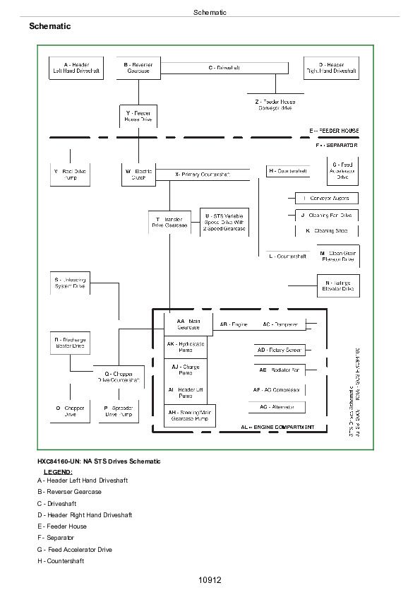
Schematic................10912
Diagnostics................10914
Group 15C: Engine Diagnostics - Type B................2298
Theory of Operation................10910
Schematics................10878
Diagnostics................10914
Group 15D: Engine Diagnostics - Type C................2298
Theory of Operation................10910
Schematic................10912
Diagnostics................10914
Group 20: Component Identification and Location................10948
Component Identification and Location................10948
Section 230: Air Intake and Cooling System................2624
Group 05: General Information................10907
General Information................10907
Group 10: Test Procedures and Adjustments................10871
Test Procedures and Adjustments................10871
Group 15A: Air Intake System Diagnostics................10914
Theory of Operation................10910
Schematics................10878
Diagnostics................10914
Group 15B: Cooling Package Type Identification................10075
Engine Cooling System Type Identification................10075
Group 15C: Cooling Package Diagnostics - Type A................2624
Theory of Operation................10910
Schematics................10878
Diagnostics................10914
Group 15D: Cooling Package Diagnostics - Type B................2624
Theory of Operation................10910
Schematic................10912
Diagnostics................10914
Group 20: Component Identification and Location................10948
Component Identification and Location................10948
Section 240: Electrical System................2774
Group 5: How To Use This Diagnostic Information................2774
General Information................10907
Group 10A: Accessing Diagnostic Trouble Codes and Addresses................2774
Armrest Display Unit (ADU) Diagnostic Addresses................2833
Armrest Display Unit (ADU) Diagnostic Trouble Code Menu................2839
Group 10B: Diagnostic Addresses by Controller................2774
Diagnostic Addresses - ADU - Armrest Display Unit................2850
Diagnostic Addresses - CAB - Control Unit CAB, 0 - 99................2857
Diagnostic Addresses - CAB - Control Unit CAB, 100 - 151................2873
Diagnostic Addresses - CAB - Control Unit CAB, 152 - 256................2887
Diagnostic Addresses - CDU - Corner Post Display Unit, 1 - 48................2901
Diagnostic Addresses - CDU - Corner Post Display Unit, 49 - 236................2914
Diagnostic Addresses - ECU - Control Unit ECU................2929
Diagnostic Addresses - HMM - Harvest Monitoring Module................2938
Diagnostic Addresses - LC1 - Control Unit LC1, 1 - 152................2945
Diagnostic Addresses - LC1 - Control Unit LC1, 153 - 236................2962
Diagnostic Addresses - LC2 - Control Unit LC2, 1 - 150................2979
Diagnostic Addresses - LC2 - Control Unit LC2, 151 - 236................2989
Diagnostic Addresses - PTP - Control Unit PTP................2998
Diagnostic Addresses - RCU - Control Unit RCU, 1 - 150................3011
Diagnostic Addresses - RCU - Control Unit RCU, 151 - 236................3028
Diagnostic Addresses - SFC - Control Unit SFC................3044
Diagnostic Addresses - SSU - Control Unit SSU................3047
Diagnostic Addresses - VCM - Control Unit VCM................3055
Diagnostic Addresses - GreenStar Display 2100/2600................3063
Diagnostic Addresses - StarFire Receiver 300................3072
Diagnostic Addresses - Control Unit iTC (StarFire iTC)................3076
Diagnostic Addresses - Control Unit iTC (StarFire 3000)................3083
Group 10C: Machine Setting Addresses................2774
Machine Setting Addresses - ADU - Armrest Display Unit................3093
Machine Setting Addresses - CAB - Control Unit CAB................3095
Machine Setting Addresses - CDU - Corner Post Display Unit................3109
Machine Setting Addresses - HMM - Harvest Monitoring Module................3111
Machine Setting Addresses - LC1 - Control Unit LC1................3112
Machine Setting Addresses - LC2 - Control Unit LC2................3124
Machine Setting Addresses - PTP - Control Unit PTP................3129
Machine Setting Addresses - RCU - Control Unit RCU................3134
Machine Setting Addresses - SFC - Control Unit SFC................3142
Machine Setting Addresses - SSU - Control Unit SSU................3144
Machine Setting Addresses - VCM - Control Unit VCM................3146
Group 10D: Diagnostic Trouble Codes, Warning Messages and Fault Codes................2775
Diagnostic Trouble Codes - ADU - Armrest Display Unit................3151
Diagnostic Trouble Codes - CAB - Control Unit CAB and Cab Power Module................3153
Diagnostic Trouble Codes - CDU - Cornerpost Display Unit................3164
Diagnostic Trouble Codes - ECU - Engine Control Unit................3166
Diagnostic Trouble Codes - HMM - Moisture Sensor................3183
Diagnostic Trouble Codes - LC1 - Control Unit LC1 and Left Power Module 1, Table 1 of 2................3185
Diagnostic Trouble Codes - LC1 - Control Unit LC1 and Left Power Module 1, Table 2 of 2................3197
Diagnostic Trouble Codes - LC2 - Control Unit LC2 and Left Power Module 2................3213
Diagnostic Trouble Codes - PTP - Control Unit PTP................3228
Codes - PTP - Startup Codes................3239
Diagnostic Trouble Codes - RCU - Control Unit RCU and Right Power Module................3241
Diagnostic Trouble Codes - SFC - Control Unit SFC................3253
Diagnostic Trouble Codes - SSU - Control Unit SSU................3255
Codes - SSU - Last Exit Codes................3263
Diagnostic Trouble Codes - VCM - Control Unit VCM, Table 1 of 2................3267
Diagnostic Trouble Codes - VCM - Control Unit VCM, Table 2 of 2................3277
Diagnostic Trouble Codes - GreenStar Display................3285
Diagnostic Trouble Codes - VTi (GreenStar Display 1800, 2100, and 2600)................3288
Diagnostic Trouble Codes - GreenStar Mobile Processor................3292
Diagnostic Trouble Codes - GreenStar Harvest Doc Harvest Doc is a trademark of Deere & Company................2775
Diagnostic Trouble Codes - KeyCard................3294
Diagnostic Trouble Codes - LCR - StarFire 300................3295
Diagnostic Trouble Codes - StarFire (iTC and 3000)................3297
Diagnostic Trouble Codes - StarFire Receiver................3301
Diagnostic Trouble Codes - Terrain Compensation Module................3302
Group 10E: Calibration Procedures................2776
Calibration Procedures - When to Calibrate................3307
Calibration Procedures - User Calibrations................3309
Calibration Procedures - Repair................3311
Calibration Procedures - Automatic Shift - Multi-Function Lever Position................3312
Calibration Procedures - Automatic Shift - Hydrostatic and Transmission Solenoids................3316
Calibration Procedures - Automatic Shift - Hydrostatic Pump................3319
Calibration Procedures - Automatic Shift - Front Hydrostatic Motor................3324
Calibration Procedures - Automatic Shift - Transmission Brake and Clutch Pressure................3328
Calibration Procedures - Automatic Steering Calibration................3332
Calibration Procedures - Cab Temperature Adjust................3333
Calibration Procedures - Cab Temperature Control Door................3337
Calibration Procedures - Chassis Tilt Position Sensor................3340
Calibration Procedures - Chopper Vane Position Sensor................3343
Calibration Procedures - Feeder House Range................3348
Calibration Procedures - Folding Auger Position Sensor................3352
Calibration Procedures - Hazard Lights Current................3356
Calibration Procedures - Lateral Tilt Angle Sensor................3359
Calibration Procedures - Recirculation Fan Speed Adjust................3364
Calibration Procedures - Chaffer Actuator................3368
Calibration Procedures - Sieve Actuator................3371
Group 15A: Active Header Height Control Type Identification................10075
Active Header Height Control Type Identification................10075
Group 15B: Active Header Height Diagnostics - Type A................2776
Theory of Operation................10910
Schematic................10912
Diagnostics................10914
Group 15C: Active Header Height Diagnostics - Type B................2776
Theory of Operation................10910
Schematic................10912
Diagnostics................10914
Group 15D: Active Header Height Diagnostics - Type C................2777
Theory of Operation................10910
Schematic................10912
Diagnostics................10914
Group 15E: Active Header Height Diagnostics - Type D................2777
Theory of Operation................10910
Schematic................10912
Diagnostics................10914
Group 15F: Active Header Height Diagnostics - Type E................2777
Theory of Operation................10910
Schematic................10912
Diagnostics................10914
Group 15G: Active Header Height Diagnostics - Type F................2777
Theory of Operation................10910
Schematics................10878
Diagnostics................10914
Group 15H: Active Header Height Diagnostics - Type G................2777
Theory of Operation................10910
Schematic................10912
Diagnostics................10914
Group 15I: Active Header Height Diagnostics - Type H................2777
Theory of Operation................10910
Schematics................10878
Diagnostics................10914
Group 15J: Air Seat Diagnostics................10914
Theory of Operation................10910
Schematic................10912
Diagnostics................10914
Group 15K: Alternator and Battery Diagnostics................10914
Theory of Operation................10910
Schematic................10912
Diagnostics................10914
Group 15L: Area Counter Diagnostics................10914
Theory of Operation................10910
Schematic................10912
Diagnostics................10914
Group 15M: Armrest Display Unit Overall Diagnostics................10914
Theory of Operation................10910
Schematic................10912
Diagnostics................10914
Group 15N: Auxiliary Power Strip Outlet Diagnostics................10914
Theory of Operation................10910
Schematic................10912
Diagnostics................10914
Group 15O: Backup Alarm Type Identification................10075
Backup Alarm Type Identification................10075
Group 15P: Backup Alarm Diagnostics - Type A................2778
Theory of Operation................10910
Schematic................10912
Diagnostics................10914
Group 15Q: Backup Alarm Diagnostics - Type B................2778
Theory of Operation................10910
Schematic................10912
Diagnostics................10914
Group 15R: CAN Bus Diagnostics................10914
Theory of Operation................10910
Schematic................10912
Diagnostics................10914
Group 15S: Chassis Tilt Diagnostics................10914
Theory of Operation................10910
Schematic................10912
Diagnostics................10914
Group 15T: Chopper Raise/Lower Type Identification................10075
Chopper Raise-Lower Type Identification................10075
Group 15U: Chopper Raise/Lower Diagnostics - Type A................2779
Theory of Operation................10910
Schematic................10912
Diagnostics................10914
Group 15V: Chopper Raise/Lower Diagnostics - Type B................2779
Theory of Operation................10910
Schematic................10912
Diagnostics................10914
Group 15W: Chopper Speed Sensor Diagnostics................10914
Theory of Operation................10910
Schematic................10912
Diagnostics................10914
Group 15X: Chopper Vane Angle Diagnostics................10914
Theory of Operation................10910
Schematic................10912
Diagnostics................10914
Group 15Y: Clean Grain Elevator Speed Sensor Diagnostics................10914
Theory of Operation................10910
Schematic................10912
Diagnostics................10914
Group 15Z: Cleaning Fan Speed Adjust Diagnostics................10914
Theory of Operation................10910
Schematic................10912
Diagnostics................10914
Group 15AA: Cleaning Fan Speed Display Diagnostics................10914
Theory of Operation................10910
Schematic................10912
Diagnostics................10914
Group 15AB: Control Unit CAB/CPM Overall Diagnostics................10914
Theory of Operation................10910
Schematic................10912
Diagnostics................10914
Group 15AC: Control Unit CDU Overall Diagnostics................10914
Theory of Operation................10910
Schematic................10912
Diagnostics................10914
Group 15AD: Control Unit ECU Overall Type Identification................10075
Control Unit ECU Overall Type Identification................10075
Group 15AE: Control Unit ECU Overall Diagnostics - Type A................2780
Theory of Operation................10910
Schematic................10912
Diagnostics................10914
Group 15AF: Control Unit ECU Overall Diagnostics - Type B................2780
Theory of Operation................10910
Schematic................10912
Diagnostics................10914
Group 15AG: Control Unit LC1/LPM1 Overall Diagnostics................10914
Theory of Operation................10910
Schematic................10912
Diagnostics................10914
Group 15AH: Control Unit LC2/LPM2 Overall Diagnostics................10914
Theory of Operation................10910
Schematic................10912
Diagnostics................10914
Group 15AI: Control Unit PTP Overall Diagnostics................10914
Theory of Operation................10910
Schematic................10912
Diagnostics................10914
Group 15AJ: Control Unit RCU/RPM Overall Diagnostics................10914
Theory of Operation................10910
Schematic................10912
Diagnostics................10914
Group 15AK: Control Unit SFC Overall Diagnostics................10914
Theory of Operation................10910
Schematic................10912
Diagnostics................10914
Group 15AL: Control Unit SSU Overall Diagnostics................10914
Theory of Operation................10910
Schematic................10912
Diagnostics................10914
Group 15AM: Control Unit VCM Overall Diagnostics................10914
Theory of Operation................10910
Schematic................10912
Diagnostics................10914
Group 15AN: Conveyor Auger Speed Sensor Diagnostics................10914
Theory of Operation................10910
Schematic................10912
Diagnostics................10914
Group 15AO: Corn Head Chopper Speed Sensor Diagnostics................10914
Theory of Operation................10910
Schematic................10912
Diagnostics................10914
Group 15AP: Cutterbar Pressure Adjust Diagnostics................10914
Theory of Operation................10910
Schematic................10912
Diagnostics................10914
Group 15AQ: Deck Plate Adjust Type Identification................10075
Deck Plate Adjust Type Identification................10075
Group 15AR: Deck Plate Adjust Diagnostics - Type A................2781
Theory of Operation................10910
Schematic................10912
Diagnostics................10914
Group 15AS: Deck Plate Adjust Diagnostics - Type B................2781
Theory of Operation................10910
Schematic................10912
Diagnostics................10914
Group 15AT: Deck Plate Display Diagnostics................10914
Theory of Operation................10910
Schematic................10912
Diagnostics................10914
Group 15AU: Deck Plate Resume Diagnostics................10914
Theory of Operation................10910
Schematic................10912
Diagnostics................10914
Group 15AV: Discharge Beater Speed Sensor Diagnostics................10914
Theory of Operation................10910
Schematic................10912
Diagnostics................10914
Group 15XX: Draper Belt Slippage Detection System Diagnostics................10914
Theory of Operation................10910
Schematic................10912
Group 15AW: Draper Cutterbar Tilt Adjust Diagnostics................10914
Theory of Operation................10910
Schematic................10912
Diagnostics................10914
Group 15AX: Draper Frame Float Type Identification................10075
Type Identification................10075
Group 15AY: Draper Frame Float Adjust Diagnostics - Type A................2782
Theory of Operation................10910
Schematic................10912
Diagnostics................10914
Group 15AZ: Draper Frame Float Adjust Diagnostics - Type B................2782
Theory of Operation................10910
Schematic................10912
Diagnostics................10914
Group 15BA: Draper Speed Adjust Type Identification................10075
Draper Speed Adjust Type Identification................10075
Group 15BB: Draper Speed Adjust Diagnostics - Type A................2783
Theory of Operation................10910
Schematics................10878
Diagnostics................10914
Group 15BC: Draper Speed Adjust Diagnostics - Type B................2783
Theory of Operation................10910
Schematic................10912
Diagnostics................10914
Group 15BD: Electric Fuel Pump Type Identification................10075
Electric Fuel Pump Type Identification................10075
Group 15BE: Electric Fuel Pump Diagnostics - Type A................2783
Theory of Operation................10910
Schematic................10912
Diagnostics................10914
Group 15BF: Electric Fuel Pump Diagnostics - Type B................2783
Theory of Operation................10910
Schematic................10912
Diagnostics................10914
Group 15BG: Electric Fuel Pump Diagnostics - Type C................2783
Theory of Operation................10910
Schematic................10912
Diagnostics................10914
Group 15BH: Engine Air Filter Sensor Diagnostics................10914
Theory of Operation................10910
Schematic................10912
Diagnostics................10914
Group 15BI: Engine and Fuel Control Type Identification................10075
Engine And Fuel Control Type Identification................10075
Group 15BJ: Engine and Fuel Control Diagnostics - Type A................2783
Theory of Operation................10910
Schematics................10878
Diagnostics................10914
Group 15BK: Engine and Fuel Control Diagnostics - Type B................2784
Theory of Operation................10910
Schematics................10878
Diagnostics................10914
Group 15BL: Engine and Fuel Control Diagnostics - Type C................2784
Theory of Operation................10910
Schematics................10878
Diagnostics................10914
Group 15BM: Engine Coolant Temperature Sensor Diagnostics................10914
Theory of Operation................10910
Schematic................10912
Diagnostics................10914
Group 15BN: Engine Oil Pressure Sensor Diagnostics................10914
Theory of Operation................10910
Schematic................10912
Diagnostics................10914
Group 15BO: Feed Accelerator Speed Sensor Diagnostics................10914
Theory of Operation................10910
Schematic................10912
Diagnostics................10914
Group 15BP: Feeder House Filter Switch Type Identification................10075
Feeder House Filter Switch Type Identification................10075
Group 15BQ: Feeder House Filter Switch Diagnostics - Type A................2784
Theory of Operation................10910
Schematic................10912
Diagnostics................10914
Section 250: Power Train System................8655
Group 05: General Information................10907
General Information................10907
Group 10: Test Procedures and Adjustments................10871
Test Procedures and Adjustments................10871
Front Motor Regulation Set Point Adjustment.................8759
Hydrostatic High Pressure Test - Hydrostatic Drive - Two-Range Automatic Transmission- Diagnostic................8760
Hydrostatic Charge Pressure Test - Hydrostatic Drive - Two-Range Automatic Transmission- Diagnostic................8763
Hydrostatic System Flushing Procedure................8769
Multi-Function Lever Response - Hydrostatic Drive - Two-Range Automatic Transmission - Diagnostic................8770
Two-Range Automatic Transmission - Shift Adjust - Diagnostic................8773
Two-Range Automatic Transmission Regulated Pressure Test................8775
Group 15A: Final Drive Diagnostics................10914
Theory of Operation................10910
Schematic................10912
Diagnostics................10914
Group 15B: Transmission Type Identification................10075
Type Identification................10075
Group 15C: Transmission Diagnostics - Type A................8655
Theory of Operation................10910
Schematic................10912
Diagnostics................10914
Group 15D: Transmission Diagnostics - Type B................8655
Theory of Operation................10910
Schematic................10912
Diagnostics................10914
Group 15E: Hydrostatic Drive Type Identification................10075
Hydrostatic Drive Type Identification................10075
Group 15F: Hydrostatic Drive Diagnostics - Type A................8655
Theory of Operation................10910
Schematic................10912
Diagnostics................10914
Group 15G: Hydrostatic Drive Diagnostics - Type B................8656
Theory of Operation................10910
Schematic................10912
Diagnostics................10914
Group 15H: Hydrostatic Drive Diagnostics - Type C................8656
Theory of Operation................10910
Schematic................10912
Diagnostics................10914
Group 20: Component Identification and Location................10948
Component Identification and Location................10948
Section 255: Four Wheel Drive System................9044
Group 05: General Information................10907
General Information................10907
Group 10: Test Procedures and Adjustments................10871
Test Procedures and Adjustments................10871
Group 15A: Two Speed Four Wheel Drive Type Identification................10075
Type Identification................10075
Group 15B: Two Speed Four Wheel Drive Diagnostics - Type A................9044
Theory of Operation................10910
Schematic................10912
Diagnostics................10914
Group 15C: Two Speed Four Wheel Drive Diagnostics - Type B................9044
Theory of Operation................10910
Schematic................10912
Diagnostics................10914
Group 20: Component Identification and Location................10948
Component Identification and Location................10948
Section 260: Brake System................9171
Group 05: General Information................10907
General Information................10907
Group 10: Test Procedures and Adjustments................10871
Test Procedures and Adjustments................10871
Group 15A: Park Brake Type Identification................10075
Type Identification................10075
Group 15B: Park Brake Diagnostics - Type A................9171
Theory of Operation................10910
Schematic................10912
Diagnostics................10914
Group 15C: Park Brake Diagnostics - Type B................9171
Theory of Operation................10910
Schematic................10912
Diagnostics................10914
Group 15D: Service Brakes Type Identification................10075
Type Identification................10075
Group 15E: Service Brakes Diagnostics - Type A................9171
Theory of Operation................10910
Schematic................10912
Diagnostics................10914
Group 15F: Service Brakes Diagnostics - Type B................9171
Theory of Operation................10910
Schematic................10912
Diagnostics................10914
Group 20: Component Identification and Location................10948
Component Identification and Location................10948
Section 270: Hydraulic System................9310
Group 05: General Information................10907
General Information................10907
Group 10: Test Procedures And Adjustments................9310
Test Procedures and Adjustments................10871
Header Lift Accumulator Precharge Test................9368
600D - Accumulator Precharge Pressure Test................9310
Overall Accumulator Precharge Testing................9387
Group 15A: Basic Hydraulic System Type ID................9310
Basic Hydraulic System Type Identification................10075
Group 15B: Basic Hydraulic System Diagnostics - Type A................9310
Theory of Operation................10910
Schematic................10912
Diagnostics................10914
Group 15C: Basic Hydraulic System Diagnostics - Type B................9310
Theory of Operation................10910
Schematic................10912
Diagnostics................10914
Group 15D: Belt Pickup Drive Type Identification................10075
Belt Pickup Type Identification................10075
Group 15E: Belt Pickup Drive Diagnostics - Type A................9310
Theory of Operation................10910
Schematic................10912
Diagnostics................10914
Group 15F: Belt Pickup Drive Diagnostics - Type B................9310
Theory of Operation................10910
Schematic................10912
Diagnostics................10914
Group 15G: Belt Pickup Drive Diagnostics - Type C................9310
Theory of Operation................10910
Schematic................10912
Diagnostics................10914
Group 15H: Chassis Tilt Diagnostics................10914
Theory of Operation................10910
Schematic................10912
Diagnostics................10914
Group 15I: Cutterbar Pressure Adjust Diagnostics................10914
Theory of Operation................10910
Schematic................10912
Diagnostics................10914
Group 15J: Deck Plate Adjust Diagnostics - Type Identification................10075
Type Identification................10075
Group 15K: Deck Plate Adjust Diagnostics - Type A................9311
Theory of Operation................10910
Schematic................10912
Diagnostics................10914
Group 15L: Deck Plate Adjust Diagnostics - Type B................9311
Theory of Operation................10910
Schematic................10912
Diagnostics................10914
Group 15M: Draper Auger Drive Diagnostics................10914
Theory of Operation................10910
Schematic................10912
Diagnostics................10914
Group 15N: Draper Belt Drive Type Identification................10075
Type Identification................10075
Group 15O: Draper Belt Drive Diagnostics - Type A................9311
Theory of Operation................10910
Schematic................10912
Diagnostics................10914
Group 15P: Draper Belt Drive Diagnostics - Type B................9311
Theory of Operation................10910
Schematic................10912
Diagnostics................10914
Group 15Q: Draper Cutterbar Pressure Diagnostics................10914
Theory of Operation................10910
Schematic................10912
Diagnostics................10914
Group 15R: Draper Cutterbar Tilt Diagnostics................10914
Theory of Operation................10910
Schematic................10912
Diagnostics................10914
Group 15S: Draper Frame Float Diagnostics Type Identification................10075
Draper Frame Float Type Identification................10075
Group 15T: Draper Frame Float Diagnostics - Type A................9312
Theory of Operation................10910
Schematic................10912
Diagnostics................10914
Group 15U: Draper Frame Float Diagnostics - Type B................9312
Theory of Operation................10910
Schematics................10878
Diagnostics................10914
Group 15V: Draper Frame Float Diagnostics - Type C................9312
Theory of Operation................10910
Schematics................10878
Diagnostics................10914
Group 15W: Feeder House Gearcase Cooler Diagnostics................10914
Theory of Operation................10910
Schematic................10912
Diagnostics................10914
Group 15X: Feeder House Reverser Shift Diagnostics................10914
Theory of Operation................10910
Schematic................10912
Diagnostics................10914
Group 15Y: Feeder House Speed Adjust Type Identification................10075
Feeder House Speed Adjust Type Identification................10075
Group 15Z: Feeder House Speed Adjust Diagnostics - Type A................9313
Theory of Operation................10910
Schematic................10912
Diagnostics................10914
Group 15AA: Feeder House Speed Adjust Diagnostics - Type B................9313
Theory of Operation................10910
Schematic................10912
Diagnostics................10914
Group 15AB: Folding Corn Head Diagnostics................10914
Theory of Operation................10910
Schematic................10912
Diagnostics................10914
Group 15AC: Header Raise/Lower Diagnostics................10914
Theory of Operation................10910
Schematic................10912
Diagnostics................10914
Group 15AD: Hydraulic System Overheating Diagnostics................10914
Theory of Operation................10910
Schematics................10878
Diagnostics................10914
Group 15AE: Lateral Tilt Type Identification................10075
Lateral Tilt Type Identification................10075
Group 15AF: Lateral Tilt Diagnostics - Type A................9313
Theory of Operation................10910
Schematic................10912
Diagnostics................10914
Group 15AG: Lateral Tilt Diagnostics - Type B................9313
Theory of Operation................10910
Schematic................10912
Diagnostics................10914
Group 15AH: Multi-coupler Diagnostics................10914
Theory of Operation................10910
Schematic................10912
Diagnostics................10914
Group 15AI: Reel Drive Type Identification................10075
Type Identification................10075
Group 15AJ: Reel Drive Diagnostics - Type A................9314
Theory of Operation................10910
Schematic................10912
Diagnostics................10914
Group 15AK: Reel Drive Diagnostics - Type B................9314
Theory of Operation................10910
Schematic................10912
Diagnostics................10914
Group 15AL: Reel Fore/Aft Type Identification................10075
Type Identification................10075
Group 15AM: Reel Fore/Aft Diagnostics - Type A................9314
Theory of Operation................10910
Schematic................10912
Diagnostics................10914
Group 15AN: Reel Fore/Aft Diagnostics - Type B................9314
Theory of Operation................10910
Schematic................10912
Diagnostics................10914
Group 15AO: Reel Raise/Lower Type Identification................10075
Reel Raise-Lower Type Identification................10129
Group 15AP: Reel Raise/Lower Diagnostics - Type A................9314
Theory of Operation................10910
Schematic................10912
Diagnostics................10914
Group 15AQ: Reel Raise/Lower Diagnostics - Type B................9314
Theory of Operation................10910
Schematic................10912
Diagnostics................10914
Group 15AR: Reel Raise-Lower Diagnostics - Type C................9315
Theory of Operation................10910
Schematic................10912
Diagnostics................10914
Group 15AS: Reel Raise/Lower Diagnostics - Type D................9315
Theory of Operation................10910
Schematic................10912
Diagnostics................10914
Group 15AT: Spreader System Type Identification................10244
Spreader System Type Identification................10244
Group 15AU: Spreader Diagnostics - Type A................9315
Theory of Operation................10910
Schematic................10912
Diagnostics................10914
Group 15AV: Spreader Diagnostics - Type B................9315
Theory of Operation................10910
Schematic................10912
Diagnostics................10914
Group 15AW: Threshing Speed Adjust Diagnostics................10914
Theory of Operation................10910
Schematic................10912
Diagnostics................10914
Group 15AX: Unloading Auger Swing Diagnostics................10914
Theory of Operation................10910
Schematic................10912
Diagnostics................10914
Group 15AY: Windscreen Raise/Lower Diagnostics................10914
Theory of Operation................10910
Schematic................10912
Diagnostics................10914
Group 20: Component Identification and Location................10948
Component Identification and Location................10948
Section 275: Main Gearcase System................10542
Group 05: General Information................10907
General Information................10907
Group 10: Test Procedures and Adjustments................10871
Test Procedures and Adjustments................10871
Group 15A: Main Gearcase Overall Diagnostics Type Identification................10075
Main Gearcase Overall Type Identification................10570
Group 15B: Main Gearcase Overall Diagnostics Type A................10542
Theory of Operation................10910
Schematics................10878
Diagnostics................10914
Group 15C: Main Gearcase Overall Diagnostics Type B................10542
Theory of Operation................10910
Schematic................10912
Diagnostics................10914
Group 15D: Main Gearcase Filter Restricted Diagnostics................10914
Theory of Operation................10910
Schematics................10878
Diagnostics................10914
Group 15E: Main Gearcase Pressure Low Diagnostics Type Identification................10611
Main Gearcase Pressure Low Diagnostics Type Identification................10611
Group 15F: Main Gearcase Pressure Low Diagnostics - Type A................10542
Theory of Operation................10910
Schematic................10912
Diagnostics................10914
Group 15G: Main Gearcase Pressure Low Diagnostics - Type B................10542
Theory of Operation................10910
Schematic................10912
Diagnostics................10914
Group 15H: Main Gearcase Temperature High Diagnostics................10914
Theory of Operation................10910
Schematic................10912
Diagnostics................10914
Group 15I: Separator Engage Diagnostics................10914
Theory of Operation................10910
Schematics................10878
Diagnostics................10914
Group 15J: Unloading Auger Engage Diagnostics................10914
Theory of Operation................10910
Schematics................10878
Diagnostics................10914
Group 20: Component Identification and Location................10948
Component Identification and Location................10948
Section 280: Steering System................10752
Group 05: General Information................10907
General Information................10907
Group 10: Test Procedures and Adjustments................10871
Test Procedures and Adjustments................10871
Group 15A: Steering System Type Identification................10778
Steering System Type Identification................10778
Group 15B: Steering Diagnostics - Type A................10752
Theory of Operation................10910
Schematic................10912
Diagnostics................10914
Group 15C: Steering Diagnostics - Type B................10752
Theory of Operation................10910
Schematic................10912
Diagnostics................10914
Group 20: Component Identification and Location................10948
Component Identification and Location................10948
Section 290: Heating, Ventilating and Air Conditioning System................10847
Group 05: General Information................10907
General Information................10907
Group 10: Test Procedures and Adjustments................10871
Test Procedures and Adjustments................10871
Group 15: Heating, Ventilation and Air Conditioning Diagnostics................10914
Theory of Operation................10910
Schematics................10878
Diagnostics................10914
Group 20: Component Identification and Location................10948
Component Identification and Location................10948
Section 300: Separator System................10905
Group 05: General Information................10907
General Information................10907
Group 15: Separator Vibration Diagnostics................10914
Theory of Operation................10910
Schematic................10912
Diagnostics................10914
Group 20: Component Identification and Location................10948
Component Identification and Location................10948
TM101819 - Operation & Tests Technical Manual for John Deere Combines Models 9570 STS, 9670 STS, 9770 STS, 9870 STS


