John Deere PowerTech 13.5L OEM Diesel Engines Base Engine Repair Component Technical Manual (CTM415)
Catalog:
Model:
John Deere PowerTech™ 13.5L OEM Diesel Engines Base Engine Repair - (Worldwide Edition) Component Technical Manual (including maintenance, overhaul, disassembling & assembling, adjustment, tune-up, operation, inspecting, diagnosis & troubleshooting…) is divided into different sections. Each section covers a specific component or system with detailed illustrations. A table of contents is placed at the beginning of each section. Pages are easily found by category, and each page is expandable for great detail. The printer-ready PDF documents work like a charm on all kinds of devices.
This manual contains high quality images, circuit diagrams, instructions to help you to maintenance, troubleshoot, diagnose, and repair. This document is printable, without restrictions, contains searchable text, bookmarks, crosslinks for easy navigation.
CTM415 English - PowerTech™ 13.5L OEM Diesel Engines Base Engine Repair - (Worldwide Edition) Component Technical Manual (CTM).pdf
ctm418 German - PowerTech™ 13,5-l-OEM-Dieselmotoren Reparatur des Grundmotors -: (Weltweite Ausgabe).pdf
TABLE OF CONTENTS
Section 01: General Information................20
Group 000: Safety................20
Avoid Heating Near Pressurized Fluid Lines................24
Avoid High-Pressure Fluids................25
Avoid Hot Exhaust................26
Avoid Static Electricity Risk When Refueling................27
Construct Dealer-Made Tools Safely................29
Decommissioning — Proper Recycling and Disposal of Fluids and Components................30
Follow Safety Instructions................31
Handle Agricultural Chemicals Safely................32
Handle Fluids Safely—Avoid Fires................34
Handling Batteries Safely................35
Illuminate Work Area Safely................37
Install All Guards................38
Live With Safety................39
Park Machine Safely................40
Practice Safe Maintenance................41
Precautions for Welding................43
Prepare for Emergencies................45
Prevent Acid Burns................46
Prevent Battery Explosions................48
Prevent Machine Runaway................49
Protect Against High Pressure Spray................50
Protect Against Noise................51
Recognize Safety Information................52
Remove Paint Before Welding or Heating................53
Replace Safety Signs................54
Service Cooling System Safely................55
Service Machines Safely................56
Stay Clear of Rotating Drivelines................57
Support Machine Properly................58
Understand Signal Words................59
Use Proper Lifting Equipment................60
Use Proper Tools................61
Use Steps and Handholds Correctly................62
Wait Before Opening High-Pressure Fuel System................579
Wear Protective Clothing................64
Work in Clean Area................65
Work In Ventilated Area................66
Group 001: Engine Identification and Applications................21
Engine Model Designation................69
Engine Serial Number Plate Information................71
Engine Option Code Label................72
Group 002: Fuels, Lubricants and Coolant................21
Diesel Fuel................75
Diesel Fuel Additive Products................77
BioDiesel Fuel................78
Minimizing the Effect of Cold Weather on Diesel Engines................80
Handling and Storing Diesel Fuel................82
Lubricity of Diesel Fuel................83
Testing Diesel Fuel................84
Fuel Filters................85
Engine Oil and Filter Service Intervals................86
Diesel Engine Oil — Tier 3 and Stage III................87
Diesel Engine Break-In Oil — Non-Emissions Certified and Certified Tier 1, Tier 2, Tier 3, Stage I, Stage II, and Stage III................89
Oil Filters................91
Grease................92
Alternative and Synthetic Lubricants................93
Lubricant Storage................94
Mixing of Lubricants................95
Diesel Engine Coolant (engine with wet sleeve cylinder liners)................96
Supplemental Coolant Additives................98
Operating in Warm Temperature Climates................99
Additional Information About Diesel Engine Coolants and John Deere LIQUID COOLANT CONDITIONER................100
Diesel Engine Coolant................102
Testing Diesel Engine Coolant................103
Drain Intervals for Diesel Engine Coolant................104
Section 02: Repair and Adjustments................105
Group 010: Engine Rebuild Guide, Break-In and Tune-Up................105
Engine Overhaul Guidelines................113
Engine Repair Stand................114
Safety Precautions................115
Disconnect Turbocharger Oil Inlet Line................116
Install Adapter on Repair Stand................118
Engine Lifting Procedure................119
Mount Engine on Repair Stand................121
Clean Engine................123
6135 Engine Disassembly Sequence................105
Sealant Application Guidelines................127
6135 Engine Assembly Sequence................105
Engine Break-In Guidelines................132
Perform Engine Break-In................133
Check Crankcase Ventilation System................135
Check Air Intake System................136
Check Exhaust System................138
Check and Service Cooling System................139
Check Electrical System................140
Group 020: Cylinder Head and Valves................105
Remove and Install Rocker Arm Cover................144
Clean and Inspect Crankcase Ventilation Assembly................146
Replace Rocker Arm Cover Gasket................147
Check and Adjust Valve Assembly Clearances and Injector Preload................148
Remove Rocker Arm Assembly................157
Remove Cylinder Head................159
Diagnosing Head Gasket Joint Failures................163
Head Gasket Inspection and Repair Sequence................165
Disassemble and Inspect Rocker Arms and Shaft Assembly................167
Preliminary Cylinder Head and Valve Checks................169
Assemble Rocker Arms and Shaft Assembly................171
Check Valve Height in Relation to Head Surface (Valve Recess)................172
Remove Valve Assembly................173
Inspect and Measure Valve Springs................175
Inspect Valve Rotators................176
Clean, Inspect, and Measure Valves................177
Grind Valves................178
Clean and Inspect Cylinder Head................179
Check Cylinder Head Flatness................181
Measure Cylinder Head Thickness................182
Measure Valve Guide ID................183
Replace Valve Guides................184
Clean and Inspect Valve Seats................186
Valve Seat — Grinding................187
Remove Valve Seat Inserts................189
Measure Valve Seat Bore in Cylinder Head................190
Install Valve Seat Inserts................191
Install Valves................192
Replace Unit Injector Sleeve in Cylinder Head Using JDG981................732
Replace Unit Injector Sleeve in Cylinder Head Using JDG1184................742
Remove Unit Injector Sleeve Using JDG10014................746
Clean and Inspect Top Deck of Cylinder Block................213
Measure Cylinder Liner Standout (Height Above Block)................241
Install Cylinder Head................216
Torque-Turn Cylinder Head Cap Screws................218
Install Rocker Arm Assembly................221
Complete Final Assembly for Cylinder Head Installation................225
Group 030: Cylinder Block, Liners, Pistons, and Rods................106
Remove and Install Cylinder Block Front Plate................229
Preliminary Liner, Piston, and Rod Checks................232
Connecting Rods—General Information................234
Remove Piston Spray Jets................235
Remove Pistons and Connecting Rods................237
Measure Cylinder Liner Standout (Height Above Block)................241
Remove Cylinder Liners Using D01062AA or D01073AA Cylinder Liner Puller................243
Remove Cylinder Liners Using JDG1145 Cylinder Liner Service Set................245
Visually Inspect Cylinder Liners................248
Deglaze Cylinder Liners................251
Clean Cylinder Liners................252
Cylinder Liner Manufacturing Date Code Explanation................253
Disassemble Piston/Rod Assembly and Clean Piston................255
Check Piston Oil Control Ring Groove Wear................257
Inspect Piston Pin and Pin Bore in Piston................258
Determine Piston-to-Liner Clearance................260
Measure Liner Flange Thickness................262
Inspect and Measure Connecting Rod Bearings................263
Inspect Connecting Rod and Cap................265
Inspect Piston Pins and Rod Bushings................269
Complete Disassembly of Cylinder Block (If Required)................271
Inspect and Clean Cylinder Block................273
Cylinder Block — Inspect and Reclaim................275
Cylinder Block — Measurements................289
Install Cylinder Liner Shim................290
Install Cylinder Liner O-Rings and Packings................291
Install Cylinder Liners................293
Assemble Pistons and Connecting Rods................295
Install Pistons and Connecting Rods................297
Torque-Turn Connecting Rod Cap Screws................301
Check Engine Rotation for Excessive Tightness................303
Install Piston Spray Jets................304
Measure Piston Protrusion................306
Complete Final Assembly................383
Group 040: Crankshaft, Main Bearings, and Flywheel................107
Crankshaft Rubber Damper Torque Sequence................310
Inspect Crankshaft Vibration Damper................311
Check Crankshaft End Play................313
Remove Crankshaft Rubber Damper and Pulley................314
Remove Viscous Damper and Front Crankshaft Oil Seal................316
Remove Timing Gear Cover................319
Check Flywheel Housing Face Runout................321
Check Flywheel Face Flatness................323
Remove Flywheel................324
Inspect and Repair Flywheel................325
Replace Flywheel Ring Gear................326
Remove and Install Flywheel Housing................327
Install Flywheel................329
Remove Rear Crankshaft Oil Seal and Housing Assembly................332
Crankshaft Unitized Rear Oil Seal — Removal................335
Crankshaft Unitized Rear Oil Seal and Housing — Installation................337
Crankshaft and Main Bearing Failure Analysis................342
Remove Crankshaft Main Bearings................343
Check Main Bearing-to-Journal Oil Clearance................345
Remove Crankshaft................346
Inspect Crankshaft................348
Measure Assembled ID of Bearings and OD of Crankshaft Journals................350
Measure Assembled ID of Main Bearing Caps (Without Bearings)................351
Replace Crankshaft Drive Gear................352
Inspect Thrust Bearings................354
Thrust Bearing New Part Specifications................355
Install Main and Thrust Bearing Inserts in Block................356
Install Crankshaft................358
Install Crankshaft Rear Oil Seal Housing................362
Install Crankshaft Rear Oil Seal and Wear Sleeve Assembly................364
Install Timing Gear Cover................366
Install Crankshaft Rubber Damper and Front Oil Seal................372
Install Viscous Damper Assembly and Front Oil Seal................377
Complete Final Assembly................383
Group 050: Camshaft and Timing Gear Train................108
Camshaft Timing Pin................385
Check and Adjust Camshaft-to-Crankshaft Timing................386
Adjust Front Timing Gear Backlash Using JDG993................735
Adjust Front Timing Gear Backlash Without Using JDG993................735
Remove and Install Camshaft................399
Replace Fuel Supply Pump Drive Pin................406
Visually Inspect Camshaft and Roller Followers................407
Inspect and Measure Camshaft Bushing ID and Journal OD................408
Measure Camshaft Lobe Lift Height................409
Inspect Camshaft Position Sensor Lobe................410
Replace Camshaft Bushings................411
SAE “A” (Front) and SAE “B” (Rear) Auxiliary Drive Assembly................417
SAE B Rear Auxiliary Drive — Removal and Installation................419
Align SAE “A” Front Auxiliary Drive Adapter................421
Group 060: Lubrication System................109
Oil Filter and Oil Conditioning Housing Assembly................425
Remove Oil Filter and Valve Housing/Oil Cooler Cover and Valve Housing................427
Inspect and Replace Oil Filter Adapter................428
Remove, Inspect, and Install Oil Pressure Regulating Valve................429
Remove, Inspect, and Install Oil Cooler and Oil Filter Bypass Valves................430
Remove, Inspect, and Install Oil Pressure Relief Valve................432
Remove, Clean, and Inspect Engine Oil Cooler................433
Install Oil Cooler/Oil Filter Valve Housing Assembly or Oil Cooler Cover/Valve Housing Assembly................436
Remove Engine Oil Pump................439
Clean and Inspect Oil Pump and Drive Gear................441
Install Engine Oil Pump................442
Remove Engine Oil Pan................445
Remove and Install Oil Pickup Tube................446
Install Engine Oil Pan................447
Oil Dipstick Tube Assembly — Installation................451
Oil Dipstick Tube Assembly — Removal................454
Group 070: Cooling System................109
Replace Bearings in Fan Drive Assembly................459
Inspect and Check Belt Tensioner Spring Tension................463
Replace Belt Tensioner Assembly................465
Remove Coolant Pump................467
Clean and Inspect Coolant Pump Parts................469
Install Coolant Pump................471
Remove and Install Thermostat Cover and Thermostats................472
Test Thermostat Opening Temperature................474
Remove and Install Thermostat Housing and Coolant Tubes................476
Remove and Install Coolant Heater—if Equipped................478
Bleed Air from Coolant System................480
Group 080: Air Intake and Exhaust System................110
Extending Turbocharger Life................485
Remove and Install Variable Geometry Turbocharger Actuator................488
Remove and Install Actuator Linkage................490
Remove Turbocharger................494
Turbocharger — Failure Analysis................499
Turbocharger Seven-Step Inspection................502
Perform Radial Bearing Clearance Test................508
Turbocharger — Repair................510
Prelube Turbocharger................511
Install Turbocharger................512
Turbocharger Break-In................517
Recommendations for Turbocharger Use................518
Remove, Inspect, and Install EGR Cooler................519
Exhaust Manifold — Remove................535
Exhaust Manifold — Install................536
Remove, Inspect, and Install Intake Manifold................530
Remove, Inspect, and Install EGR Valve (Tier 3/Stage III A)................532
Group 081: Air Intake and Exhaust System — PowerTech™ E Engines................110
Exhaust Manifold — Remove................535
Exhaust Manifold — Install................536
Turbocharger — Remove................538
Turbocharger — Install................540
Air Intake Manifold — Remove................543
Air Intake Manifold — Install................544
Group 082: Air Intake and Exhaust System — Marine Engines................111
Air Intake Manifold (Marine) — Removal................552
Air Intake Manifold (Marine) — Installation................558
Exhaust Manifold (Marine) — Removal................565
Exhaust Manifold (Marine) — Installation................568
Turbocharger (Marine) — Removal................571
Turbocharger (Marine) — Installation................574
Group 090: Fuel System................579
Fuel System................579
Group 100: Starting and Charging Systems................111
Remove and Install Alternator (OEM Engines)................582
Remove and Install Starter Motor (OEM Engines)................584
Section 03: Theory of Operation................585
Group 120: Base Engine Operation — PowerTech Plus................585
General Engine Operation................611
Lubrication System Operation................614
Cooling System Operation................617
Fuel System Theory of Operation................620
Head Gasket Joint Construction and Operation................621
Intake and Exhaust System Operation................623
Exhaust Gas Recirculator (EGR) Exhaust Gas Recirculator (EGR) & Variable Geometry Turbocharger (VGT) Operation{pgNO}585 Variable Geometry Turbocharger (VGT) Operation................602
Turbocharger Operation................624
How the Turbocharger is Lubricated................626
Group 121: Base Engine Operation — PowerTech & PowerTech E................585
General Engine Operation................611
Lubrication System Operation................614
Cooling System Operation................617
Fuel System Theory of Operation................620
Head Gasket Joint Construction and Operation................621
Intake and Exhaust System Operation................623
Turbocharger Operation................624
How the Turbocharger is Lubricated................626
Section 04: Diagnostics................627
Group 150: Observable Diagnostics and Tests................627
About this Section of the Manual................629
13.5L - L1 - Excessive Oil Consumption................627
13.5L - L2 Engine Oil Pressure High................627
13.5L - L3 - Engine Oil Pressure Low................627
13.5L - L4 - Fuel in Oil................627
13.5L - L5 - Soot or Sludge in the Oil................627
13.5L - C1 - Engine Coolant Temperature Above Normal................627
13.5L - C2 - Engine Coolant Temperature Below Normal................627
13.5L Engines - C3 - Coolant in Oil or Oil in Coolant................627
13.5L Engines - C4 - Coolant Leaking from Weep Hole................627
Dynamometer Test................642
Check Cylinder Compression................643
Engine Oil Consumption................646
Check Engine Oil Pressure................647
Check for Excessive Engine Crankcase Pressure (Blow-By) (Base Pressure)................648
Check for Turbocharger Oil Seal Leak................659
Inspect Thermostat and Test Opening Temperature................660
Cooling System Pressure Test................662
Charge Air Cooler Test................665
Check for Head Gasket Failures................667
Check Intake Manifold Pressure (Turbo Boost)................670
Check Intake Manifold Pressure (Turbo Boost) — Fix Geometry Turbocharger................671
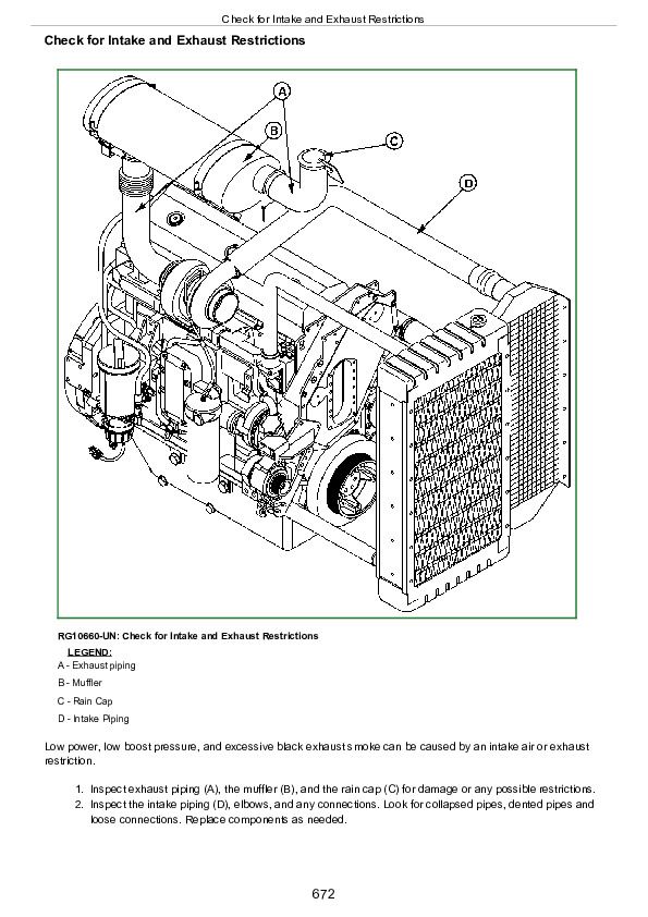
Check for Intake and Exhaust Restrictions................672
Check for Intake Air Leaks................674
Check for Exhaust Air Leaks................676
Check Camshaft-to-Crankshaft Timing................677
Check Crankshaft Position Sensor Depth................679
Check Engine Cranking Speed................681
EGR Cooler Test................682
Excessive Engine Vibration................683
Section 05: Tools and Other Materials................774
Group 170: Special Tools................687
75240................687
D01062AA................692
D01168AA................693
D01200AA................694
D01218AA................695
D01300AA................696
D05012ST-A................697
D05104ST................698
D05223ST................699
D01073AA................700
D17006BR................701
D17015BR................702
D17024BR................703
D17525CI................704
D17526CI................705
D17527CI................706
DFRG3................707
DFRG4................709
DFRG9................710
DFRG11................712
JDE41296................714
JDG164A................715
JDG451................716
JDG782A................717
JDG820................718
JDG839................719
JDG967................720
JDG968................721
JDG969A................722
JDG970B................723
JDG971................724
JDG972................725
JDG973................726
JDG974A................727
JDG975................728
JDG976................729
JDG977................730
JDG978................731
JDG981................732
JDG981-1................733
JDG982A................734
JDG993................735
JDG996................736
JDG1020................737
JDG1069................738
JDG1144................739
JDG1145................740
JDG1167................741
JDG1184................742
JDG1333................743
JDG1334................744
JDG1847................745
JDG10014................746
JDG10194................747
JDG10199................748
JDG10200................749
JDG10246A................750
JDG10249................751
JDG10357B................752
JDG10539A................753
JDG10668................754
JDG10996................755
JDG10997................756
JDG11008................757
JDG11056................758
JDG11084................759
JDG11334P3................760
JDG11373................761
JDG11374................762
JDG11544................763
JDG11831................764
JDG11860................765
JDG11864................766
JT01674A................767
JT05412................768
JT05697A................769
JT05993................770
JT07336................771
Group 180: Lubricants, Sealants, and Other Materials................774
Other Materials................774
Section 06: Specifications................776
Group 200: Repair and General OEM Specifications................776
General OEM Engine Specifications................778
Unified Inch Bolt and Screw Torque Values................779
Metric Bolt and Screw Torque Values................781
Engine Rebuild Guide, Break-In and Tune-Up (Group 010) Specifications................783
Cylinder Head and Valves (Group 020) Specifications................784
Cylinder Block, Liners, Pistons and Rods (Group 030) Specifications................787
Crankshaft, Main Bearings and Flywheel (Group 040) Specifications................790
Camshaft and Timing Gear Train (Group 050) Specifications................792
Lubrication System (Group 060) Specifications................793
Cooling System (Group 070) Specifications................795
Air Intake and Exhaust System (Group 080) Specifications — Variable Geometry Turbocharger................796
Air Intake and Exhaust System (Group 081) Specifications — Fixed Geometry Turbocharger................797
Starting and Charging Systems (Group 100) Specifications................798
Group 210: Diagnostic Specifications................776
Observable Diagnostics and Test Specifications................800
Dynamometer Test Specifications (OEM Engines)................801
Intake Manifold Pressure (Turbocharger Boost) Specifications................804
John Deere PowerTech 13.5L OEM Diesel Engines Base Engine Repair Component Technical Manual (CTM415)


