Komatsu Bulldozers D39EX, D39PX Repair Service Manuals
Catalog:
Model:
Complete service repair manual with Electrical Wiring Diagrams for Komatsu Bulldozers D39EX, D39PX, with all the technical information to maintain, diagnose, repair, and service like professional mechanics.
Komatsu Bulldozers D39EX,PX workshop service repair manual includes:
* Numbered table of contents easy to use so that you can find the information you need fast.
* Detailed sub-steps expand on repair procedure information
* Numbered instructions guide you through every repair procedure step by step.
* Troubleshooting and electrical service procedures are combined with detailed wiring diagrams for ease of use.
* Notes, cautions and warnings throughout each chapter pinpoint critical information.
* Bold figure number help you quickly match illustrations with instructions.
* Detailed illustrations, drawings and photos guide you through every procedure.
* Enlarged inset helps you identify and examine parts in detail.
SEBM023809 - Bulldozer D39EX,PX-21 Shop Manual (SN1001&up).pdf
SEBM023810 - Bulldozer D39EX,PX-21 Shop Manual (SN1001&up).pdf
SEN04041-05 - Bulldozer D39EX,PX-22 Shop Manual (SN3001&up).pdf
PRODUCT DETAILS:
Total Pages: 1,920 pages
File Format: PDF
Language: English
TABLE OF CONTENTS
01 GENERAL ... 01-1
10 STRUCTURE AND FUNCTION, MAINTENANCE STANDARD ... 10-1
20 TESTING AND ADJUSTING ... 20-1
30 DISASSEMBLY AND ASSEMBLY ... 30-1
90 OTHERS ...90-1
SEBM023809 - Bulldozer D39EX,PX-21 Shop Manual (SN1001&up)...2
COVER...2
CONTENTS...3
SAFETY...8
SAFETY NOTICE...8
FOREWORD...10
GENERAL...10
HOW TO READ THE SHOP MANUAL...11
HOISTING INSTRUCTIONS...12
METHOD OF DISASSEMBLING, CONNECTING PUSH-PULL TYPE COUPLER...13
COATING MATERIALS...15
STANDARD TIGHTENING TORQUE...17
ELECTRIC WIRE CODE...20
CONVERSION TABLE...21
UNITS...27
01 GENERAL...28
SPECIFICATION DRAWING...29
SPECIFICATIONS...30
WEIGHT TABLE...34
TABLE OF FUEL, COOLANT AND LUBRICANTS...36
10 STRUCTURE AND FUNCTION, MAINTENANCE STANDARD...37
COOLING SYSTEM...38
ENGINE CONTROL...39
POWER TRAIN...41
POWER TRAIN SYSTEM...42
HST HYDRAULIC EQUIPMENT ARRANGEMENT DIAGRAM...43
STEERING, BRAKE CONTROL...44
DAMPER...50
SOLENOID VALVE...51
FINAL DRIVE...53
HST PUMP...57
SAFETY-SUCTION VALVE...62
CUT-OFF VALVE...65
CHARGE SAFETY VALVE...66
CHARGE PUMP...68
HST BRAKE QUICK RETURN CIRCUIT...69
TOWING VALVE...70
PARKING BRAKE VALVE...71
AS VALVE...73
HST MOTOR...75
STEERING, DIRECTIONAL PPC VALVE...86
INCHING VALVE...95
AUTOMATIC GEARSHIFITING VALVE...97
FRAME ASSEMBLY...102
TRACK FRAME, RECOIL SPRING...103
IDLER...105
TRACK ROLLER ...107
CARRIER ROLLER...108
SPROCKET...109
TRACK SHOE...111
ARRANGEMENT OF HYDRAULIC EQUIPMENT FOR WORK EQUIPMENT...115
WORK EQUIPMENT CONTROL...116
HYDRAULIC TANK, FILTER...118
HYDRAULIC PUMP...119
WORK EQUIPMENT CYLINDER...120
SUCTION VALVE...122
CONTROL VALVE...124
CLSS...132
WORK EQUIPMENT PPC VALVE...142
WORK EQUIPMENT ...149
CUTTING EDGE, END BIT...152
CAB RELATED...153
SAFETY MECHANISM WHEN STARTING ENGINE...154
GEARSHIFT CONTROL SYSTEM...155
PARKING BRAKE CONTROL SYSTEM...156
COMPONENT EQUIPMENT OF SYTEM...157
MONITOR SYSTEM...159
SENSORS...163
20 TESTING AND ADJUSTING...166
STANDARD VALUE TABLE...167
STANDARD VALUE TABLE FOR ENGINE...167
STANDARD VALUE FOR CHASSIS...168
STANDARD VALUE TABLE FOR ELECTRICAL PARTS...172
TESTING AND ADJUSTING...175
TOOLS FOR TESTING AND ADJUSTING...176
MEASURING ENGINE SPEED...177
MEASURING EXHAUST COLOR...178
MEASURING BLOW-BY PRESSURE...179
MEASURING INTAKE AIR PRESSURE (BOOST PRESSURE)...180
ADJUSTING VALVE CLEARANCE...181
TESTING AND ADJUSTING FUEL INJECTION TIMING...183
MEASURING COMPRESSION PRESSURE...184
ADJUSTING ENGINE STOP SOLENOID LINKAGE...185
MEASURING ENGINE OIL PRESSURE...186
BLEEDING AIR FROM FUEL CIRCUIT...187
TESTING AND ADJUSTING TENSION OF AIR CONDITIONER COMPRESSOR BELT...188
MEASURING AND ADJUSTING HST OIL PRESSURE...189
MEASURING SOLENOID VALVE OUTPUT PRESSURE...194
MEASURING AND ADJUSTING WORK EQUIPMENT MAIN RELIEF PRESSURE...195
MEASURING PPC VALVE OUTPUT PRESSURE...197
MEASURING LEAKAGE INSIDE CYLINDER...198
BLEEDING AIR FROM HYDRAULIC CYLINDERS...198
TESTING AND ADJUSTING TRACK SHOE TENSION...199
TESTING AND ADJUSTING TRAVEL DEVIATION...200
ADJUSTING FUEL CONTROL LINKAGE...203
ADJUSTING DECELERATION PEDAL LINKAGE...205
ADJUSTING BRAKE PEDAL LINKAGE...206
ADJUSTING STEERING/DIRECTIONAL/GEAR SHIFT LEVER AND LOCK LEVER...208
ADJUSTING BLADE CONTROL LEVER AND LOCK LEVER...211
ADJUSTING WORK EQUIPMENT PPC VALVE...212
PROCEDURE FOR RELEASING PARKING BRAKE...213
PROCEDURE FOR INSPECTING DIODE...215
TROUBLESHOOTING...216
POINTS TO REMEMBER WHEN TROUBLESHOOTING...217
SEQUENCE OF EVENTS IN TROUBLESHOOTING...218
POINTS TO REMEMBER WHEN CARRYING OUT MAINTENANCE...219
CHECKS BEFORE TROUBLESHOOTING...227
METHOD OF USING TROUBLESHOOTING CHARTS...228
TYPES AND LOCATIONS OF CONNECTORS...229
CONNECTOR ARRANGEMENT DIAGRAM...231
CONNECTION TABLE FOR CONNECTOR PIN NUMBERS...233
TROUBLESHOOTING FOR ELECTRICAL SYSTEM (E-MODE)...255
TABLE OF FAILURE MODES AND CAUSES (ELECTRICAL SYSTEM)...256
ELECTRICAL CIRCUIT DIAGRAM FOR EACH SYSTEM...258
E-1 WHEN STARTING SWITCH IS TURNED ON, STARTING MOTOR DOES NOT ROTATE...260
E-2 ENGINE DOES NOT START (ENGINE STOP SOLENOID DOES NOT OPERATE NORMALLY)...262
E-3 HEADLAMP DOES NOT LIGHT UP...263
E-4 WHEN STARTING SWITCH IS TURNED TO HEAT POSITION, ENGINE IS NOT HEATED...265
E-5 WINDSHEILD WIPER DOES NOT OPERATE...266
E-6 WASHING WATER DOES NOT SPOUT ...268
E-7 AIR CONDITIONER DOES NOT WORK...270
A) AIR DOES NOT BLOW OUT...270
B) AIR IS NOT COOLED...273
E-8 PARKING BRAKE CANNOT BE RELEASED (PARKING BRAKE SOLENOID DOES NOT OPERATE)...277
E-9 TRAVEL SPEED CONTROL IS ABNORMAL...278
A) WHEN GEAR SHIFT SWITCH IS PRESSED, GEAR SPEED DOES NOT CHANGE OR GEAR SPEED CHANGES BY ITSELF (GEAR SHIFT SWITCH OR CONTRO...278
B) GEAR SPEED CANNOT BE SELECTED NORMALLY (TRAVEL SPEED CHANGEOVER SOLENOID IS ADNORMAL...279
E-10 BACKUP ALARM DOES NOT SOUND DURING REVERSE TRAVEL...281
E-11 HORN DOES NOT SOUND...283
TROUBLESHOOTING FOR HYDRAULIC AND MECHANICAL SYSTEM (H-MODE)...284
TABLE OF FAILURE MODES AND CAUSES (HYDRAULIC AND MECHANICAL SYSTEMS)...285
H-1 MACHINE DOES NOT TRAVEL IN EITHER DIRECTION OR IT STOPS SUDDENLY...287
H-2 MACHINE DOES NOT TRAVEL IN ONE DIRECTION...288
H-3 MACHINE TRAVELS WHILE TRAVEL LEVER IS IN NEUTRAL...288
H-5 MACHINE DEVIATES WHILE TRAVEL LEVER IS IN PARTIAL POSITION ...288
H-7 MACHINE SWINGS MOMENTARILY WHEN IT STARTS ON FLAT GROUND...288
H-11 TURNING TIME LAG IS LARGE...288
H-12 WHEN OPERATOR INTENDS TO TURN GRADUALLY, MACHINE TURNS SHARPLY...288
H-13 MACHINE DOES NOT RETURN QUICKLY TO STRAIGHT TRAVEL POSITION...288
H-14 MACHINE IS NOT DECELERATED SMOOTHLY OR TRAVEL SPEED CANNOT BE CONTROLLED ON DOWNHILL GROUND...288
H-15 MACHINE DEVIATES WHEN IT IS DECELERATED...288
H-4 MACHINE DEVIATES WHEN TRAVEL LEVER IS MOVED TO STROKE END...289
H-6 MACHINE MOVES BACK WHEN OPERATOR STARTS ON UPHILL GROUND...289
H-8 MACHINE STARTS SHARPLY...289
H-9 MACHINE SWINGS MOMENTARILY WHEN IT STARTS...290
H-10 STARTING TIME LAG IS LARGE...291
H-16 MAXIMUM TRAVEL SPEED IS LOW OR OUTPUT POWER IS INSUFFICIENT OR ACCELERATION IS LOW...292
H-17 ENGINE STALLS...293
H-18 HST NOISE IS LARGE...294
H-19 HST OIL TEMPERATURE RISES TOO HIGH...295
H-20 GEAR SPEED DOES NOT CHANGE...295
H-21 ABNORMAL SOUND IS HEARD FROM AROUND WORK EQUIPMENT PUMP OR HST PUMP...296
H-22 ANY WORK EQUIPMENT DOES NOT MOVE...296
H-23 SPEED OR POWER OF EACH WORK EQUIPMENT IS LOW...297
H-24 SPEED OR POWER OF BLADE LIFT OF BLADE TILT CYLINDER IS LOW...297
H-25 SPEED OR POWER OF BLADE ANGLE CYLINDER IS LOW...298
H-26 HYDRAULIC DRIFT OF BLADE LIFT CYLINDER IS LARGE...299
H-27 HYDRAULIC DRIFT OF BLADE TILT CYLINDER IS LARGE...299
H-28 HYDRAULIC DRIFT OF BLADE ANGLE CYLINDER IS LARGE...300
TROUBLESHOOTING FOR MACHINE MONITOR SYSTEM (M-MODE)...301
TABLE OF FAILURE MODES AND CAUSES ( MACHINE MONITOR SYSTEMS)...302
ELECTRIC CIRCUIT DIAGRAM FOR EACH SYSTEM...303
M-1 WHEN STARTING SWITCH IS TURNED ON, MONITOR PANEL IS NOT TURNED ON...305
M-2 TROUBLE IN PREHESTING CAUTION LAMP...306
A) PREHEATING MONITOR DOES NOT LIGHT UP...306
B) PREHEATING MONITOR KEEPS LIGHTING UP...306
M-3 CAUTION ITEM LIGHTS UP...307
A) CHARGE CAUTION LAMP LIGHTS UP WHILE ENGINE IS RUNNING...307
B) OIL PRESSURE CAUTION LAMP LIGHTS UP WHILE ENGINE IS RUNNING...308
C) HST FILTER CLOGGING LAMP LIGHTS UP (WHILE FILTER IS NOT CLOGGED)...308
M-4 TROUBLE IS HST OIL TEMPERATURE GAUGE...309
A) GAUGE DOES NOT RISE ABOVE C (LOWEST POINT)...309
B) GAUGE DOES NOT LOWER BELOW H (HIGHEST POINT)...309
C) HST OIL TEMPERATURE INDICATED BY GAUGE IS DIFFERENT FROM ACTUAL TEMPERATURE...310
M-5 TROUBLE IN ENGINE WATER TEMPERATURE GAUGE...311
A) GAUGE DOES NOT RISE ABOVE C (LOWEST POINT)...311
B) GAUGE DOES NOT LOWER BELOW H (HIGHEST POINT)...311
C) HST OIL TEMPERATURE INDICATED BY GAUGE IS DIFFERENT FROM ACTUAL TEMPERATURE...312
M-6 TROUBLE IN FUEL LEVEL GAUGE...313
A) GAUGE DOES NOT RISE ABOVE E (LOWEST POINT)...313
B) GAUGE DOES NOT LOWER BELOW F (HIGHEST POINT)...313
C) FUEL LEVEL INDICATED BY GAUGE IS DIFFERENT FROM ACTUAL LEVEL...314
M-7 SERVICE METER DOES NOT OPERATE AFTER ENGINE IS STARTED...315
M-8 MONITOR PANEL LAMP DOES NOT LIGHT UP (WHILE HEADLAMP IS NORMAL)...316
M-9 TROUBLE IN DISPLAY OF TRAVEL SPEED (WHILE ACTUAL TRAVEL SPEED IS NORMAL)...317
A) TRAVEL SPEED IS NOT DISPLAYED...317
B) DISPLAYED SPEED IS DIFFERENT FROM ACTUAL TRAVEL SPEED...317
30 DISASSEMBLY AND ASSEMBLY...321
METHOD OF USING MANUAL...322
PRECAUTIONS WHEN CARRYING OUT OPERATION...323
SPECIAL TOOL LIST...325
SKETCHES OF SPECIAL TOOLS...327
REMOVAL OF FUEL INJECTION PUMP ASSEMBLY...328
INSTALLATION OF FUEL INJECTION PUMP ASSEMBLY...330
REMOVAL OF CYLINDER HEAD ASSEMBLY...332
INSTALLATION OF CYLINDER HEAD ASSEMBLY...337
REMOVAL OF ENGINE FRONT SEAL...339
INSTALLATION OF ENGINE FRONT SEAL...340
REMOVAL OF ENGINE REAR SEAL...341
INSTALLATION OF ENGINE REAR SEAL...342
REMOVAL OF RADIATOR GUARD ASSEMBLY...343
INSTALLATION OF RADIATOR GUARD ASSEMBLY...345
DISASSEMBLY OF RADIATOR, OIL COOLER, AND CHARGE AIR COOLER ASSEMBLIES...346
ASSEMBLY OF RADIATOR, OIL COOLER, AND CHARGE AIR COOLER ASSEMBLIES...348
REMOVAL OF ENGINE ASSEMBLY...350
INSTALLATION OF ENGINE ASSEMBLY...352
REMOVAL OF DAMPER...353
INSTALLATION OF DAMPER...353
REMOVAL OF TRAVEL MOTOR AND FINAL DRIVE ASSEMBLY...354
INSTALLATION OF TRAVEL MOTOR AND FINAL DRIVE ASSEMBLY...355
DISASSEMBLY OF TRAVEL MOTOR AND FINAL DRIVE ASSEMBLY...356
ASSEMBLY OF TRAVEL MOTOR AND FINAL DRIVE ASSEMBLY...360
REMOVAL OF IDLER AND RECOIL SPRING ASSEMBLY...365
INSTALLATION OF IDLER AND RECOIL SPRING ASSEMBLY...365
DISASSEMBLY OF RECOIL SPRING ASSEMBLY...366
ASSEMBLY OF RECOIL SPRING ASSEMBLY...367
DISASSEMBLY OF IDER ASSEMBLY...369
ASSEMBLY OF IDER ASSEMBLY...370
DISASSEMBLY OF TRACK ROLLER ASSEMBLY...372
ASSEMBLY OF TRACK ROLLER ASSEMBLY...373
DISASSEMBLY OF CARRIER ROLLER ASSEMBLY...376
ASSEMBLY OF CARRIER ROLLER ASSEMBLY...377
SPREADING TRACK SHOE ASSEMBLY...378
INSTALLATION OF TRACK SHOE ASSEMBLY...379
REMOVAL OF HST PUMP ASSEMBLY...380
INSTALLATION OF HST PUMP ASSEMBLY...381
REMOVAL OF MAIN CONTROL VALVE ASSEMBLY...382
INSTALLATION OF MAIN CONTROL VALVE ASSEMBLY...383
DISASSEMBLY OF MAIN CONTROL VALVE ASSEMBLY...384
ASSEMBLY OF MAIN CONTROL VALVE ASSEMBLY...388
DISASSEMBLY OF HYDRAULIC CYLINDER ASSEMBLIES...392
ASSEMBLY OF HYDRAULIC CYLINDER ASSEMBLIES...393
REMOVAL OF BLADE ASSEMBLY...395
INSTALLATION OF BLADE ASSEMBLY...396
REMOVAL OF OPERATOR'S CAB FRAME ASSEMBLY...397
INSTALLATION OF OPERATOR'S CAB FRAME ASSEMBLY...400
REMOVAL OF FUEL TANK ASSEMBLY...401
INSTALLTION OF FUEL TANK ASSEMBLY...401
REMOVAL OF HYDRAULIC TANK ASSEMBLY...402
INSTALLATION OF HYDRAULIC TANK ASSEMBLY...403
90 OTHERS ...405
HYDRAULIC CIRCUIT DIAGRAM (1/2) D39EX-21: 1001-1200; D39PX-21: 1001-1208...406
HYDRAULIC CIRCUIT DIAGRAM (1/2) D39EX-21: 1201 and up; D39PX-21: 1209 and up...407
HYDRAULIC CIRCUIT DIAGRAM (2/2)...408
ELECTRICAL CIRCUIT DIAGRAM (1/2)...409
ELECTRICAL CIRCUIT DIAGRAM (2/2)...410
ELECTRICAL CIRCUIT DIAGRAM FOR AIR CONDITIONER...411
SEBM023810 - Bulldozer D39EX,PX-21 Shop Manual (SN1001&up)...412
COVER...412
CONTENTS...413
01 GENERAL...446
SPECIFICATION DRAWING...447
SPECIFICATIONS...448
WEIGHT TABLE...452
TABLE OF FUEL, COOLANT AND LUBRICANTS...454
10 STRUCTURE AND FUNCTION, MAINTENANCE STANDARD...455
COOLING SYSTEM...456
ENGINE CONTROL...457
POWER TRAIN...458
POWER TRAIN SYSTEM...459
HST HYDRAULIC EQUIPMENT ARRANGEMENT DIAGRAM...460
STEERING, BRAKE CONTROL...462
DAMPER...468
SOLENOID VALVE...469
FINAL DRIVE...471
HST PUMP...474
SAFETY-SUCTION VALVE...479
CUT-OFF VALVE...482
CHARGE SAFETY VALVE...483
CHARGE PUMP...485
HST BRAKE QUICK RETURN CIRCUIT...486
TOWING VALVE...487
PARKING BRAKE VALVE...488
AS VALVE...490
HST MOTOR...492
STEERING, DIRECTIONAL PPC VALVE...503
INCHING VALVE...512
AUTOMATIC GEARSHIFTING VALVE...514
FRAME ASSEMBLY...519
TRACK FRAME, RECOIL SPRING...520
IDLER...522
TRACK ROLLER...524
CARRIER ROLLER...525
SPROCKET...526
TRACK SHOE...528
ARRANGEMENT OF HYDRAULIC EQUIPMENT FOR WORK EQUIPMENT...532
WORK EQUIPMENT CONTROL...533
HYDRAULIC TANK, FILTER...535
HYDRAULIC PUMP...536
WORK EQUIPMENT CYLINDER...537
SUCTION VALVE...539
CONTROL VALVE...541
CLSS...549
WORK EQUIPMENT PPC VALVE...559
WORK EQUIPMENT ...566
CUTTING EDGE, END BIT...569
CAB RELATED...570
SAFETY MECHANISM WHEN STARTING ENGINE...571
GEARSHIFT CONTROL SYSTEM...572
PARKING BRAKE CONTROL SYSTEM...573
COMPONENT EQUIPMENT OF SYSTEM...574
MONITOR SYSTEM...576
SENSORS...580
20 TESTING AND ADJUSTING...583
STANDARD VALUE TABLE FOR ENGINE...584
STANDARD VALUE TABLE FOR CHASSIS...585
STANDARD VALUE TABLE FOR ELECTRICAL SYSTEM...590
TESTING AND ADJUSTING...592
TOOLS LIST FOR TESTING AND ADJUSTING...593
MEASURING ENGINE SPEED...596
MEASURING EXHAUST COLOR...597
MEASURING BLOW-BY PRESSURE...598
MEASURING INTAKE AIR PRESSURE (BOOST PRESSURE)...599
ADJUSTING VALVE CLEARANCE...600
TESTING ADJUSTING FUEL INJECTION TIMING...602
MEASURING COMPRESSION PRESSURE...603
ADJUSTING ENGINE STOP SOLENOIDE LINKAGE...604
MEASURING ENGINE OIL PRESSURE...605
BLEEDING AIR FROM FUEL CIRCUIT...606
REPLACEMENT OF FAN BELT...607
TESTING AND ADJUSTING TENSION OF AIR CONDITIONER COMPRESSOR BELT...609
MEASURING AND ADJUSTING HST OIL PRESSURE...610
MEASURING SOLENOID VALVE OUTPUT PRESSURE...615
MEASURING AND ADJUSTING WORK EQUIPMENT MAIN RELIEF PRESSURE...616
MEASURING PPC VALVE OUTPUT PRESSURE...618
MEASURING LEAKAGE INSIED CYLINDER...619
BLEEDING AIR FROM HYDRAULIC CYLINDERS...619
TESTING AND ADJUSTING TRACK SHOE TENSION...620
TESTING AND ADJUSTING TRAVEL DEVIATION...621
ADJUSTING FUEL CONTROL LINKAGE...624
ADJUSTING DECELERATOR PEDAL LINKAGE...626
ADJUSTING BRAKE PEDAL LINKAGE...627
ADJUSTING STEERING/DIRECTIONAL/GEAR SHIFT LEVER AND LOCK LEVER...629
ADJUSTING BLADE CONTROL LEVER AND LOCK LEVER...632
ADJUSTING WORK EQUIPMENT PPC VALVE...633
PROCEDURE FOR RELEASING PARKING BRAKE...634
PROCEDURE FOR INSPECTING DIODE...636
TROUBLESHOOTING...637
POINTS TO REMEMBER WHEN TROUBLESHOOTING...638
SEQUENCE OF EVENTS IN TROUBLESHOOTING...639
HANDLING OF ELECTRIC EQUIPMENT AND HYDRAULIC COMPONENT...640
CHECKS BEFORE TROUBLESHOOTING...650
METHOD OF USING TROUBLESHOOTING CHARTS...651
TYPES AND LOCATIONS OF CONNECTORS...652
CONNECTOR ARRANGEMENT DIAGRAM...654
CONNECTION TABLE FOR CONNECTOR PIN NUMBERS...656
T-BRANCH BOX AND T-BRANCH ADAPTER TABLE...692
TROUBLESHOOTING FOR ELECTRICAL SYSTEM (E-MODE)...695
TABLE OF FAILURE MODES AND CAUSES (ELECTRICAL SYSTEM)...696
ELECTRICAL CIRCUIT DIAGRAM FOR EACH SYSTEM...698
E-1. WHEN STARTING SWITCH IS TURNED ON, STARTING MOTOR DOES NOT ROTATE...700
E-2. ENGINE DOES NOT START (ENGINE STOP SOLENOID DOES NOT OPERATE NORMALLY)...702
E-3. HEADLAMP DOES NOT LIGHT UP...703
E-4. WHEN STARTING SWITCH IS TURNED TO HEAT POSITION, ENGINE IS NOT HEATED...705
E-5. WINDSHIELD WIPER DOES NOT OPERATE...706
E-6. WASHING WATER DOES NOT SPOUT...708
E-7. AIR CONDITIONER DOES NOT WORK...710
(a) AIR DOES NOT BLOW OUT...710
(b) AIR IS NOT COOLED...713
E-8. PARKING BRAKE CANNOT BE RELEASED (PARKING BRAKE SOLENOID DOES NOT OPERATE)...717
E-9. TRAVEL SPEED CONTROL IS ABNORMAL...718
(a) WHEN GEAR SHIFT SWITCH IS PRESSED, GEAR SPEED DOES NOT CHANGE OR GEAR SPEED CHANGES BY ITSELF (GEAR SHIFT SWITCH OR CONTROLLER IS ABNORMAL)...718
(b) GEAR SPEED CANNOT BE SELECTED NORMALLY (TRAVEL SPEED CHANGEOVER SOLENOID IS ABNORMAL)...719
E-10. BACKUP ALARM DOES NOT SOUND DURING REVERSE TRAVEL...721
E-11. HORN DOES NOT SOUND...723
TROUBLESHOOTING FOR HYDRAULIC AND MECHANICAL SYSTEM (H-MODE)...724
TABLE OF FAILURE MODES AND CAUSES (HYDRAULIC AND MECHANICAL SYSTEMS)...725
H-1. MACHINE DOES NOT TRAVEL IN EITHER DIRECTION OR IT STOPS SUDDENLY...727
H-2. MACHINE DOES NOT TRAVEL IN ONE DIRECTION...728
H-3. MACHINE TRAVELS WHILE TRAVEL LEVER IS IN NEUTRAL...728
H-5. MACHINE DEVIATES WHILE TRAVEL LEVER IS IN PARTIAL POSITION...728
H-7. MACHINE SWINGS MOMENTARILY WHEN IT STARTS ON FLAT GROUND...728
H-11. TURNING TIME LAG IS LARGE...728
H-12. WHEN OPERATOR INTENDS TO TURN GRADUALLY, MACHINE TURNS SHARPLY...728
H-13. MACHINE DOES NOT RETURN QUICKLY TO STRAIGHT TRAVEL POSITION...728
H-14. MACHINE IS NOT DECELERATED SMOOTHLY OR TRAVEL SPEED CANNOT BE CONTROLLED ON DOWNHILL GROUND...728
H-15. MACHINE DEVIATES WHEN IT IS DECELERATED...728
H-4. MACHINE DEVIATES WHEN TRAVEL LEVER IS MOVED TO STROKE END...729
H-6. MACHINE MOVES BACK WHEN OPERATOR STARTS ON UPHILL GROUND...729
H-8. MACHINE STARTS SHARPLY...729
H-9. MACHINE SWINGS MOMENTARILY WHEN IT STARTS...730
H-10. STARTING TIME LAG IS LARGE...731
H-16. MAXIMUM TRAVEL SPEED IS LOW OR OUTPUT POWER IS INSUFFICIENT OR ACCELERATION IS LOW...732
H-17. ENGINE STALLS...733
H-18. HST NOISE IS LARGE...734
H-19. HST OIL TEMPERATURE RISES TOO HIGH...735
H-20. GEAR SPEED DOES NOT CHANGE...735
H-21. ABNORMAL SOUND IS HEARD FROM AROUND WORK EQUIPMENT PUMP OR HST PUMP...736
H-22. ANY WORK EQUIPMENT DOES NOT MOVE...736
H-23. SPEED OR POWER OF EACH WORK EQUIPMENT IS LOW...737
H-24. SPEED OR POWER OF BLADE LIFT OF BLADE TILT CYLINDER IS LOW...737
H-25. SPEED OR POWER OF BLADE ANGLE CYLINDER IS LOW...738
H-26. HYDRAULIC DRIFT OF BLADE LIFT CYLINDER IS LARGE...739
H-27. HYDRAULIC DRIFT OF BLADE TILT CYLINDER IS LARGE...739
H-28. HYDRAULIC DRIFT OF BLADE ANGLE CYLINDER IS LARGE...740
TROUBLESHOOTING FOR MACHINE MONITOR SYSTEM (M-MODE)...741
TABLE OF FAILURE MODES AND CAUSES (MACHINE MONITOR SYSTEM)...742
ELECTRIC CIRCUIT DIAGRAM FOR EACH SYSTEM...743
M-1. WHEN STARTING SWITCH IS TURNED ON , MONITOR PANEL IS NOT TURNED ON...745
M-2. TROUBLE IN PREHEATING CAUTION LAMP...746
(a) PREHEATING MONITOR DOES NOT LIGHT UP...746
(b) PREHEATING MONITOR KEEPS LIGHTING UP...746
M-3. CAUTION ITEM LIGHTS UP...747
(a) CHARGE CAUTION LAMP LIGHTS UP WHILE ENGINE IS RUNNING...747
(b) OIL PRESSURE CAUTION LAMP LIGHTS UP WHILE ENGINE IS RUNNING...748
(c) HST FILTER CLOGGING CAUTION LAMP LIGHTS UP (WHILE FILTER IS NOT CLOGGED)...748
M-4. TROUBLE IN HST OIL TEMPERATURE GAUGE...749
(a) GAUGE DOES NOT RISE ABOVE C (LOWEST POINT)...749
(b) GAUGE DOES NOT LOWER BELOW H (HIGHEST POINT)...749
(c) HST OIL TEMPERATURE INDICATED BY GAUGE IS DIFFERENT FROM ACTUAL TEMPERATURE...750
M-5. TROUBLE IN ENGINE WATER TEMPERATURE GAUGE...751
(a) GAUGE DOES NOT RISE ABOVE C (LOWEST POINT)...751
(b) GAUGE DOES NOT LOWER BELOW H (HIGHEST POINT)...751
(c) ENGINE WATER TEMPERATURE INDICATED BY GAUGE IS DIFFERENT FROM ACTUAL TEMPERATURE...752
M-6. TROUBLE IN FUEL LEVEL GAUGE...753
(a) GAUGE DOES NOT RISE ABOVE E (LOWEST POINT)...753
(b) GAUGE DOES NOT LOWER BELOW F (HIGHEST POINT)...753
(c) FUEL LEVEL INDICATED BY GAUGE IS DIFFERENT FROM ACTUAL LEVEL...754
M-7. SERVICE METER DOES NOT OPERATE AFTER ENGINE IS STARTED...755
M-8. MONITOR PANEL LAMP DOES NOT LIGHT UP (WHILE HEADLAMP IS NORMAL)...756
M-9. TROUBLE IN DISPLAY OF TRAVEL SPEED (WHILE ACTUAL TRAVEL SPEED IS NORMAL)...757
(a) TRAVEL SPEED IS NOT DISPLAYED...757
(b) DISPLAYED SPEED IS DIFFERENT FROM ACTUAL TRAVEL SPEED...757
TROUBLESHOOTING FOR ENGINE SYSTEM (S-MODE)...759
METHOD OF USING TROUBLESHOOTING CHARTS...760
S-1 STARTING PERFORMANCE IS POOR (STARTING ALWAYS TAKES TIME)...764
S-2 ENGINE DOES NOT START ...765
S-3 ENGINE DOES NOT PICK UP SMOOTHLY (FOLLOW-UP IS POOR) ...768
S-4 ENGINE STOPS DURING OPERATIONS...769
S-5 ENGINE DOES NOT ROTATE SMOOTHLY (HUNTING)...770
S-6 ENGINE LACKS OUTPUT (OR LACKS POWER)...771
S-7 EXHAUST SMOKE IS BLACK (INCOMPLETE COMBUSTION)...772
S-8 OIL CONSUMPTION IS EXCESSIVE (OR EXHAUST SMOKE IS BLUE)...773
S-9 OIL BECOMES CONTAMINATED QUICKLY...774
S-10 FUEL CONSUMPTION IS EXCESSIVE...775
S-11 OIL IS IN COOLANT, OR COOLANT SPURTS BACK, OR COOLANT LEVEL GOES DOWN ...776
S-12 OIL PRESSURE CAUTION LAMP LIGHTS UP (DROP IN OIL PRESSURE)...777
S-13 OIL LEVEL RISES (WATER, FUEL IN OIL)...778
S-14 COOLANT TEMPERATURE BECOMES TOO HIGH (OVERHEATING)...779
S-15 ABNORMAL NOISE IS MADE...780
S-16 VIBRATION IS EXCESSIVE...781
30 DISASSEMBLY AND ASSEMBLY...783
HOW TO READ THIS MANUAL...784
COATING MATERIALS LIST...786
SPECIAL TOOL LIST...789
SKETCHES OF SPECIAL TOOLS...791
REMOVAL OF FUEL INJECTION PUMP ASSEMBLY...792
INSTALLATION OF FUEL INJECTION PUMP ASSEMBLY...794
REMOVAL OF CYLINDER HEAD ASSEMBLY...796
INSTALLATION OF CYLINDER HEAD ASSEMBLY...801
REMOVAL OF ENGINE FRONT SEAL...803
INSTALLATION OF ENGINE FRONT SEAL...804
REMOVAL OF ENGINE REAR SEAL...805
INSTALLATION OF ENGINE REAR SEAL...806
REMOVAL OF RADIATOR GUARD ASSEMBLY...807
INSTALLATION OF RADIATOR GUARD ASSEMBLY...809
DISASSEMBLY OF RADIATOR, OIL COOLER, AND CHARGE AIR COOLER ASSEMBLIES...810
ASSEMBLY OF RADIATOR, OIL COOLER, AND CHARGE AIR COOLER ASSEMBLIES...812
REMOVAL OF ENGINE ASSEMBLY...814
INSTALLATION OF ENGINE ASSEMBLY...816
REMOVAL OF DAMPER...817
INSTALLATION OF DAMPER...817
REMOVAL OF TRAVEL MOTOR AND FINAL DRIVE ASSEMBLY...818
INSTALLATION OF TRAVEL MOTOR AND FINAL DRIVE ASSEMBLY...819
DISASSEMBLY OF TRAVEL MOTOR AND FINAL DRIVE ASSEMBLY...820
ASSEMBLY OF TRAVEL MOTOR AND FINAL DRIVE ASSEMBLY...824
REMOVAL OF IDLER AND RECOIL SPRING ASSEMBLY...829
INSTALLATION OF IDLER AND RECOIL SPRING ASSEMBLY...829
DISASSEMBLY OF RECOIL SPRING ASSEMBLY...830
ASSEMBLY OF RECOIL SPRING ASSEMBLY...831
DISASSEMBLY OF IDLER ASSEMBLY...833
ASSEMBLY OF IDLER ASSEMBLY...834
DISASSEMBLY OF TRACK ROLLER ASSEMBLY...836
ASSEMBLY OF TRACK ROLLER ASSEMBLY...837
DISASSEMBLY OF CARRIER ROLLER ASSEMBLY...840
ASSEMBLY OF CARRIER ROLLER ASSEMBLY...841
SPREADING TRACK SHOE ASSEMBLY...842
INSTALLATION OF TRACK SHOE ASSEMBLY...843
REMOVAL OF HST PUMP ASSEMBLY...844
INSTALLATION OF HST PUMP ASSEMBLY...845
REMOVAL OF MAIN CONTROL VALVE ASSEMBLY...846
INSTALLATION OF MAIN CONTROL VALVE ASSEMBLY...847
DISASSEMBLY OF MAIN CONTROL VALVE ASSEMBLY...848
ASSEMBLY OF MAIN CONTROL VALVE ASSEMBLY...852
DISASSEMBLY OF HYDRAULIC CYLINDER ASSEMBLIES...856
ASSEMBLY OF HYDRAULIC CYLINDER ASSEMBLIES...857
REMOVAL OF BALDE ASSEMBLY...859
INSTALLATION OF BLADE ASSEMBLY...860
REMOVAL OF OPERATOR'S CAB FRAME ASSEMBLY...861
INSTALLATION OF OPERATO'S CAB FRAME ASSEMBLY...865
REMOVAL OF FUEL TANK ASSEMBLY...866
INSTALLATION OF FUEL TANK ASSEMBLY...866
REMOVAL OF HYDRAULIC TANK ASSEMBLY...867
INSTALLATION OF HYDRAULIC TANK ASSEMBLY...868
90 OTHERS...869
HYDRAULIC CIRCUIT DIAGRAM (1/2)(D39EX-21 SERIAL NO.1001-1200 D39PX-21 SERIAL NO.1001-1208)...870
HYDRAULIC CIRCUIT DIAGRAM (1/2) (D39EX-21 SERIAL NO.1201 AND UP D39PX-21 SERIAL NO.1209 AND UP)...871
HYDRAULIC CIRCUIT DIAGRAM (2/2)...872
ELECTRICAL CIRCUIT DIAGRAM (1/2)...873
ELECTRICAL CIRCUIT DIAGRAM (2/2)...874
ELECTRICAL CIRCUIT DIAGRAM FOR AIR CONDITIONER...875
SEN04041-05 - Bulldozer D39EX,PX-22 Shop Manual (SN3001&up)...876
COVER...876
00 Index and foreword...0
100 Index...877
Composition of shop manual...878
Table of contents...880
200 Foreword and general information...889
Safety notice...890
How to read the shop manual...895
Explanation of terms for maintenance standard...897
Handling of electric equipment and hydraulic component...899
Handling of connectors newly used for engines...908
How to read electric wire code...911
Precautions when carrying out operation...914
Method of disassembling and connecting push-pull type coupler...917
Standard tightening torque table...920
Conversion table...924
01 General...0
100 Specification and technical data...931
Specification dimensional drawing...932
Specifications...933
Weight table...937
Table of fuel, coolant and lubricants...939
10 Structure, function and maintenance standard...0
100 Engine and cooling system...941
Engine system parts...942
Cooling system...943
Cooling fan pump...944
Cooling fan motor...945
Oil cooler bypass valve...950
200 Power train...955
Power train...956
Power train system...957
Damper...958
HST hydraulic equipment arrangement diagram...959
Steering and brake control...960
Solenoid valve...962
Final drive...969
HST pump...972
HST motor...984
Charge pump...994
300 Undercarriage and frame...997
Main frame...998
Track frame and idler cushion...1000
Idler...1002
Track roller...1004
Carrier roller...1006
Sprocket...1008
Track shoe...1010
410 Hydraulic system, Part 1...1017
Arrangement of hydraulic equipment for work equipment...1018
Work equipment control...1020
Hydraulic tank and filter...1022
Work equipment and fan pump...1024
Control valve...1032
CLSS...1044
Functions and operation of each valve...1047
420 Hydraulic system, Part 2...1057
Blade PPC valve...1058
Accumulator...1064
500 Work equipment...1067
Work equipment...1068
Cutting edge and end bit...1072
Ripper...1073
Work equipment cylinder...1074
Piston valve...1077
600 Cab and its attachments...1079
ROPS cab...1080
Cab mount...1081
Canopy mount...1082
Air conditioner...1083
700 Electrical system...1087
Monitor system...1088
Engine control...1090
Engine control system...1091
Cooling control system...1092
HST control system...1094
Parking brake control system...1100
KOMTRAX system...1102
Component equipment of system...1104
PCCS lever (for steering)...1112
Sensor...1115
20 Standard value table...0
100 Standard service value table...1127
Standard service value table for engine...1128
Standard service value table for chassis...1129
30 Testing and adjusting...0
110 Testing and adjusting, Part 1...1137
Tools for testing, adjusting, and troubleshooting...1139
Sketches of special tools...1142
Measuring engine speed...1143
Measuring intake air pressure (boost pressure)...1144
Measuring exhaust gas color (boost pressure)...1146
Adjusting valve clearance...1147
Measuring compression pressure...1149
Measuring blow-by pressure...1152
Testing engine oil pressure...1154
Handling fuel system equipment...1155
Releasing residual pressure in fuel system...1155
Bleeding air from fuel circuit...1156
Measuring fuel pressure...1157
Measuring fuel discharge, return and leakage...1159
Testing leakage in fuel system...1163
Measurement of fan circuit pressure and fan speed...1164
Adjustment of fan speed sensor...1165
Handling reduced cylinder mode operation...1166
Handling no-injection cranking operation...1166
Handling controller voltage circuit...1167
Check of muffler and muffler stack for looseness and damage...1168
Check of muffler function...1168
Check of installed condition of cylinder head and manifolds...1169
Check of engine piping for damage and looseness...1169
Replacing alternator belt...1170
120 Testing and adjusting, Part 2...1173
Adjusting decelerator pedal...1174
Testing and adjusting HST oil pressure...1176
Measuring solenoid valve outlet pressure...1181
Testing travel deviation...1184
Adjusting parking brake lever...1185
Simple brake performance test procedure...1187
Adjusting brake pedal...1188
Method of releasing parking brake (Procedure for emergency escape)...1190
Testing and adjusting idler clearance...1192
Testing and adjusting track shoe tension...1193
Testing work equipment pressure...1194
Testing work equipment PPC valve...1196
Adjusting play of work equipment PPC valve...1198
Adjusting work equipment lock lever...1199
Testing internal leakage of work equipment cylinder...1200
Releasing residual pressure in hydraulic circuit...1202
Bleeding air from hydraulic circuit...1203
Adjusting play of blade center ball...1204
Procedure for testing diodes...1205
Preparation work for troubleshooting for electrical system...1206
How to start operation of KOMTRAX terminal...1210
Lamp display of KOMTRAX terminal...1213
130 Testing and adjusting, Part 3...1217
Special functions of monitor panel (EMMS)...1218
Items to be adjusted when electric/hydraulic devices are adjusted/replaced...1280
Adjustment procedure after replacement of HST controller...1281
Adjustment procedure after replacement of monitor panel...1283
Pm-clinic...1284
40 Troubleshooting...0
100 Failure code table and fuse locations...1295
Failure code table...1296
Before carrying out troubleshooting for electrical system (E-mode)...1302
200 General information on troubleshooting...1305
Points to remember when troubleshooting...1306
Sequence of events in troubleshooting...1307
Testing before troubleshooting...1308
Classification and procedures of troubleshooting...1309
Information contained in troubleshooting table...1312
Connection table for connector pin numbers...1314
T- branch box and T- branch adapter table...1350
310 Troubleshooting by failure code (Display of code), Part 1...1355
Failure code [6091NX] HST charge filter element: Clogging...1357
Failure code [AA10NX] Air cleaner: Clogging...1358
Failure code [AB00MA] Alternator: Malfunction...1360
Failure code [B@BAZG] Engine oil: Lowering of oil pressure...1361
Failure code [B@BCNS] Coolant: Overheat...1362
Failure code [B@CRNS] HST oil: Overheating...1363
Failure code [B@CRZG] HST oil: Lowering of oil pressure...1364
Failure code [CA111] Engine controller: Abnormality in controller...1365
Failure code [CA115] Abnormal engine Ne and Bkup speed sensors: Abnormal speed sensor signal...1365
Failure code [CA122] Charge pressure sensor tool high: Excessively high voltage detected...1366
Failure code [CA123] Charge pressure sensor too low: Excessively low voltage detected...1368
Failure code [CA131] Decelerator pedal sensor tool high: Excessively high voltage detected...1370
Failure code [CA132] Decelerator pedal sensor too low: Excessively low voltage detected...1372
Failure code [CA144] Coolant temperature sensor too high: Excessively high voltage detected...1374
Failure code [CA145] Coolant temperature sensor too low: Excessively low voltage detected...1376
Failure code [CA153] Charge air temperature sensor too high: Excessively high voltage detected...1378
Failure code [CA154] Charge temperature sensor too low: Excessively low voltage detected...1380
Failure code [CA187] Sensor power source 2 too low: Excessively low voltage detected...1382
Failure code [CA221] Atmospheric pressure sensor too high: Excessively high voltage detected...1384
Failure code [CA222] Atmospheric pressure sensor too low: Excessively low voltage detected...1386
Failure code [CA227] Sensor power source 2 too high: Excessively high voltage detected...1388
Failure code [CA234] Engine over speed: Excessively high speed...1390
Failure code [CA238] Abnormal power source for Ne speed sensor: Excessively low voltage detected...1391
Failure code [CA271] IMV/PCV1 short circuit: Short circuit...1392
Failure code [CA272] IMV/PCV1 disconnection: Disconnection...1394
320 Troubleshooting by failure code (Display of code), Part 2...1397
Failure code [CA322] Injector No. 1 system disconnection or short circuit: disconnection, short circuit...1400
Failure code [CA324] Injector No. 3 system disconnection or short circuit: disconnection, short circuit...1402
Failure code [CA331] Injector No. 2 system disconnection or short circuit: disconnection, short circuit...1404
Failure code [CA332] Injector No. 4 system disconnection or short circuit: disconnection, short circuit...1406
Failure code [CA342] Engine controller data matching error: matching error...1408
Failure code [CA351] Injector drive circuit abnormality: Abnormal circuit...1410
Failure code [CA352] Sensor power source 1 too low: Excessively low voltage detected...1412
Failure code [CA386] Sensor power source 1 too high: Excessively high voltage detected...1414
Failure code [CA428] Water in fuel sensor too high: Excessively high voltage detected...1416
Failure code [CA429] Water in fuel sensor too low: Excessively low voltage detected...1418
Failure code [CA435] Abnormal engine oil pressure switch: Abnormal signal circuit...1420
Failure code [CA441] Power source voltage too low: Excessively low voltage detected...1422
Failure code [CA442] Power source voltage too high: Excessively high voltage has occurred in the controller power source circuit...1424
Failure code [CA449] Common rail pressure too high (2): Excessively high pressure trouble occurred...1426
Failure code [CA451] Common rail pressure sensor too high: Excessively high voltage detected...1428
Failure code [CA452] Common rail pressure sensor too low: Excessively low voltage detected...1430
Failure code [CA488] Charge temperature too high and torque derated: Exceeded upper control limit of temperature...1432
Failure code [CA553] Common rail pressure too high (1): Excessively high pressure detected...1433
Failure code [CA559] Loss of pressure feed from supply pump (1): Loss of pressure feed detected...1434
Failure code [CA689] Abnormal engine Ne speed sensor: Abnormal signal...1436
Failure code [CA731] Abnormal engine Bkup speed sensor phase: Abnormal phase...1438
Failure code [CA757] Loss of all engine controller data: Loss of all data...1440
Failure code [CA778] Abnormal engine Bkup speed sensor: Abnormal Bkup signal...1442
Failure code [CA1633] Abnormal KOMNET: Abnormal communication...1444
Failure code [CA2185] Decelerator pedal sensor power source too high: Excessively high voltage detected...1446
Failure code [CA2186] Decelerator pedal sensor power source too low: Excessively low voltage detected...1448
Failure code [CA2249] Loss of pressure feed from supply pump (2): Loss of pressure feed detected...1450
Failure code [CA2311] Abnormal IMV solenoid: Abnormal resistance...1452
Failure code [CA2555] Air intake heater relay disconnection: Disconnection...1454
Failure code [CA2556] Air intake heater relay short circuit: Short circuit...1456
330 Troubleshooting by failure code (Display of code), Part 3...1459
Failure code [D130KA] Neutral safety relay: Disconnection...1462
Failure code [D130KB] Neutral safety relay: Short circuit...1464
Failure code [DAFRKR] CAN communication (Monitor panel - HST controller): Defective communication (Abnormality in objective component system)...1466
Failure code [DAFRMC] CAN communication (Monitor panel - ENGINE controller): Defective communication (Abnormality in objective component system)...1469
Failure code [DAJ000] HST controller: Memory error...1472
Failure code [DAJ0KK] HST controller: Lowing of source voltage...1474
Failure code [DAJ0KQ] HST controller: Machine code error...1476
Failure code [DAJ0KT] HST controller: Memory error...1477
Failure code [DAJ5KK] HST controller sensor 5 V power supply No.1: Lowing of source voltage/Input...1478
Failure code [DAJ6KK] HST controller sensor 5 V power supply No.2: Lowing of source voltage/Input...1480
Failure code [DAJRKR] CAN communication (HST controller - Monitor panel): Defective communication (Abnormality in objective component system)...1482
Failure code [DB2RKR] CAN communication (HST controller - Engine controller): Defective communication (Abnormality in objective component system)...1485
Failure code [DD12KA] Shift up switch: Disconnection...1488
Failure code [DD12KB] Shift up switch: Short circuit...1490
Failure code [DD13KA] Shift down switch: Disconnection...1492
Failure code [DD13KB] Shift down switch: Short circuit...1494
Failure code [DD14KB] Travel lock limit switch 1: Short circuit...1496
Failure code [DD1NL4] Fan rotation selector switch: Disagreement of ON, OFF Signals...1498
Failure code [DDDCKB] Reverse travel speed switch: Short circuit...1500
Failure code [DDP6KA] Brake oil pressure sensor: Disconnection...1502
Failure code [DDP6KB] Brake oil pressure sensor: Short circuit...1504
Failure code [DDP6MA] Brake oil pressure sensor: Malfunction...1506
Failure code [DDQ2KA] Travel lock limit switch 1: Disconnection...1508
Failure code [DDT0L4] Shift mode switch: Disagreement of ON/ OFF Signals...1510
Failure code [DDU1FS] Travel lock limit switches 1 and 2: Fixing...1512
Failure code [DDU1KA] Travel lock limit switch 2: Disconnection...1514
Failure code [DDU1KY] Travel lock limit switch 2: Short circuit with power supply line...1516
Failure code [DGS1KA] HST oil temperature sensor: Disconnection...1518
Failure code [DGS1KX] HST oil temperature sensor: Out of Input signal range...1520
340 Troubleshooting by failure code (Display of code), Part 4...1523
Failure code [DHH5KA] Left HST pump pressure sensor: Disconnection...1526
Failure code [DHH5KB] Left HST pump pressure sensor: Short circuit...1528
Failure code [DHH6KA] Right HST pump pressure sensor: Disconnection...1530
Failure code [DHH6KB] Right HST pump pressure sensor: Short circuit...1532
Failure code [DK10KA] Fuel dial sensor: Disconnection...1534
Failure code [DK10KB] Fuel dial sensor: Short circuit...1536
Failure code [DK30KA] Steering angle sensor 1: Disconnection...1538
Failure code [DK30KB] Steering angle sensor 1: Short circuit...1540
Failure code [DK30KX] Steering angle sensor: Out of input signal range...1542
Failure code [DK30KZ] Steering angle sensor: Disconnection or short circuit...1543
Failure code [DK30L8] Steering angle sensor: Disagreement of analog signals...1544
Failure code [DK31KA] Steering angle sensor 2: Disconnection...1546
Failure code [DK31KB] Steering angle sensor 2: Short circuit...1548
Failure code [DK40KA] Brake pedal sensor: Disconnection...1550
Failure code [DK40KB] Brake pedal sensor: Short circuit...1552
Failure code [DK55KX] Directional potentiometer: Out of input signal range...1554
Failure code [DK55KZ] Directional potentiometer: Disconnection or short circuit...1555
Failure code [DK55L8] Directional potentiometer: Disagreement of analog signals...1556
Failure code [DK56KA] Directional potentiometer 1: Disconnection...1558
Failure code [DK56KB] Directional potentiometer 1: Short circuit...1560
Failure code [DK57KA] Directional potentiometer 2: Disconnection...1562
Failure code [DK57KB] Directional potentiometer 2: Short circuit...1564
Failure code [DLM0KX] HST motor speed sensors: Out of input signal range...1566
Failure code [DLM1KA] Left HST motor speed sensor: Disconnection...1568
Failure code [DLM1KB] Left HST motor speed sensor: Short circuit...1570
Failure code [DLM1MA] Left HST motor speed sensor: Malfunction...1572
Failure code [DLM2KA] Right HST motor speed sensor: Disconnection...1574
Failure code [DLM2KB] Right HST motor speed sensor: Short circuit...1576
Failure code [DLM2MA] Right HST motor speed sensor: Malfunction...1578
Failure code [DLM3KA] Fan speed sensor: Disconnection...1580
Failure code [DLM3KB] Fan speed sensor: Short circuit...1582
350 Troubleshooting by failure code (Display of code), Part 5...1585
Failure code [DN21FS] Brake pedal and proximity switch: Fixing...1588
Failure code [DV00KB] Caution buzzer: Short circuit...1590
Failure code [DV20KB] Back alarm buzzer: Short circuit...1591
Failure code [DW4BKA] Parking brake solenoid valve: Disconnection...1592
Failure code [DW4BKB] Parking brake solenoid valve: Short circuit...1594
Failure code [DW4BKY] Parking brake solenoid valve: Short circuit with power supply line...1596
Failure code [DW7BKA] Fan reverse solenoid valve: Disconnection...1598
Failure code [DW7BKB] Fan reverse solenoid valve: Short circuit...1600
Failure code [DW7BKY] Fan reverse solenoid valve: Short circuit with power supply line...1601
Failure code [DW7EKA] Slow brake solenoid valve: Disconnection...1602
Failure code [DW7EKB] Slow brake solenoid valve: Short circuit...1606
Failure code [DW7EKY] Slow brake solenoid valve: Short circuit with power supply line...1608
Failure code [DWN5KA] Fan EPC solenoid valve: Disconnection...1610
Failure code [DWN5KB] Fan EPC solenoid valve: Short circuit...1612
Failure code [DWN5KY] Fan EPC solenoid valve: Short circuit with power supply line...1614
Failure code [DXA4KA] LF HST pump EPC solenoid valve: Disconnection...1616
Failure code [DXA4KB] LF HST pump EPC solenoid valve: Short circuit...1618
Failure code [DXA4KY] LF HST pump EPC solenoid valve: Short circuit with power supply line...1620
Failure code [DXA5KA] LR HST pump EPC solenoid valve: Disconnection...1622
Failure code [DXA5KB] LR HST pump EPC solenoid valve: Short circuit...1624
Failure code [DXA5KY] LR HST pump EPC solenoid valve: Short circuit with power supply line...1626
Failure code [DXA6KA] RF HST pump EPC solenoid valve: Disconnection...1628
Failure code [DXA6KB] RF HST pump EPC solenoid valve: Short circuit...1630
Failure code [DXA6KY] RF HST pump EPC solenoid valve: Short circuit with power supply line...1631
Failure code [DXA7KA] RR HST pump EPC solenoid valve: Disconnection...1632
Failure code [DXA7KB] RR HST pump EPC solenoid valve: Short circuit...1634
Failure code [DXA7KY] RR HST pump EPC solenoid valve: Short circuit with power supply line...1636
Failure code [DXK1KA] Left HST motor EPC solenoid valve: Disconnection...1638
Failure code [DXK1KB] Left HST motor EPC solenoid valve: Short circuit...1639
Failure code [DXK1KY] Left HST motor EPC solenoid valve: Short circuit with power supply line...1640
Failure code [DXK2KA] Right HST motor EPC solenoid valve: Disconnection...1641
Failure code [DXK2KB] Right HST motor EPC solenoid valve: Short circuit...1642
Failure code [DXK2KY] Right HST motor EPC solenoid valve: Short circuit with power supply line...1643
400 Troubleshooting of electrical system (E-mode)...1645
E-1 Engine does not start (Starting motor does not rotate)...1648
E-2 Engine is not preheated...1651
E-3 When starting switch is turned ON, any item does not light up...1654
E-4 Charge level caution flashes while engine is running...1656
E-5 Emergency warning items flash while engine is running...1658
E-6 Preheating pilot lamp does not light up during preheating operation...1664
E-7 The coolant temperature gauge does not indicate correctly...1666
E-8 The HST oil temperature gauge does not indicate correctly...1667
E-9 Fuel level gauge does not indicate properly...1668
E-10 Gear speed, set travel speed, and shift mode indicator does not display normally...1670
E-11 Multi-information unit does not display normally...1670
E-12 Caution lamp does not flash or does not go off...1671
E-13 Caution buzzer does not sound or does not stop...1672
E-14 Reverse travel speed setting switch does not function...1674
E-15 Shift mode switch does not function...1676
E-16 Buzzer cancel switch does not function...1678
E-17 Information switch does not function...1680
E-18 The fan cleaning does not operate or cannot be reset...1682
E-19 Backup alarm does not sound...1684
E-20 The horn does not sound or does not stop...1685
E-21 Work equipment does not move...1686
E-22 Headlamp or rear lamp does not light up...1688
E-23 Foot heater does not operate...1691
E-24 Air conditioner does not operate...1694
E-25 Windshield wiper and window washer do not operate...1699
E-26 KOMTRAX system does not operate normally...1712
500 Troubleshooting of hydraulic and mechanical system (H-mode)...1715
Information in troubleshooting table...1717
H-1 Right and left travel systems do not operate forward and in reverse (No travel systems operate)...1718
H-2 Right or left travel system does not operate forward and in reverse (Only right or left travel system does not operate)...1720
H-3 Right or left travel system does not operate forward or in reverse (Only 1 system does not operate)...1721
H-4 Speed or power of travel is low...1722
H-5 Gear is not shifted...1723
H-6 Large shocks are made when machine starts and stops travel...1724
H-7 Machine deviates largely during travel...1725
H-8 Hydraulic drift of travel is large...1726
H-9 Engine stalls or engine speed lowers extremely during travel...1727
H-10 Abnormal sound comes out from around HST pump and motor...1728
H-11 Work equipment dose not operate at all...1729
H-12 Speed or power of whole work equipment is low...1730
H-13 Speed or power of lifting blade is low...1731
H-14 Speed or power of tilting blade is low...1732
H-15 Speed or power of angling blade is low...1733
H-16 Time lag in lifting blade is large...1734
H-17 Hydraulic drift of lifting blade is large...1734
H-18 Hydraulic drift of tilting blade is large...1734
H-19 Abnormal sound comes out from around work equipment pump and control valve...1735
H-20 HST oil temperature (Hydraulic oil temperature) rises too high...1736
H-21 Fan speed is abnormal (High, low, or 0 rpm)...1738
H-22 Abnormal sound is heard from around fan...1739
600 Troubleshooting of engine (S-mode)...1741
Method of using troubleshooting charts...1743
S-1 Starting performance is poor...1746
S-2 Engine does not start...1747
S-3 Engine does not pick up smoothly...1750
S-4 Engine stops during operations...1751
S-5 Engine does not rotate smoothly...1752
S-6 Engine lacks output (or lacks power)...1753
S-7 Exhaust smoke is black (imcomplete combustion)...1754
S-8 Oil consumption is excessive (or exhaust smoke is blue)...1755
S-9 Oil becomes contaminated quickly...1756
S-10 Fuel consumption is excessive...1757
S-11 Oil is in coolant (or coolant spurts back, or coolant level goes down)...1758
S-12 Oil pressure drops...1759
S-13 Oil level rises (water, fuel in oil)...1760
S-14 Coolant temperature becomes too high (overheating)...1761
S-15 Abnormal noise is made...1762
S-16 Vibration is excessive...1763
50 Disassembly and assembly...0
100 General information on disassembly and assembly...1765
How to read this manual...1766
Coating materials list...1768
Special tools list...1771
Sketches of special tools...1774
200 Engine and cooling system...1779
Removal and installation of fuel supply pump assembly...1780
Removal and installation of fuel injector assembly...1784
Removal and installation of cylinder head assembly...1792
Removal and installation of engine and HST pump assembly...1805
Removal and installation of engine front seal assembly...1808
Removal and installation of engine rear seal assembly...1810
Removal and installation of front guard assembly...1814
Removal and installation of radiator assembly...1816
Removal and installation of hydraulic oil cooler assembly...1818
Removal and installation of aftercooler assembly...1820
Removal and installation of cooling fan and motor assembly...1822
Removal and installation of cooling fan drive motor assembly1...1824
Removal and installation of fuel tank assembly...1826
300 Power train...1829
Removal and installation of HST pump assembly...1830
Removal and installation of HST motor and final drive assembly...1832
Disassembly and assembly of final drive assembly...1834
400 Undercarriage and frame...1845
Spreading and installation of track shoe assembly...1846
Removal and installation of idler and recoil spring assembly...1848
Disassembly and assembly of idler assembly...1849
Disassembly and assembly of recoil spring assembly...1852
Disassembly and assembly of track roller assembly...1856
Disassembly and assembly of carrier roller assembly...1860
500 Hydraulic system...1865
Removal and installation of hydraulic tank assembly...1866
Removal and installation of control valve assembly...1868
Disassembly and assembly of control valve assembly...1869
Disassembly and assembly of hydraulic cylinder assembly...1871
600 Work equipment...1877
Removal and installation of work equipment assembly...1878
700 Cab and its attachments...1883
Removal and installation of ROPS canopy and operator seat frame assembly...1884
Removal and installation of ROPS cab and operator seat frame assembly...1887
Removal and installation of operator’s cab glass (Stuck glass)...1892
800 Electrical system...1899
Removal and installation of HST controller assembly...1900
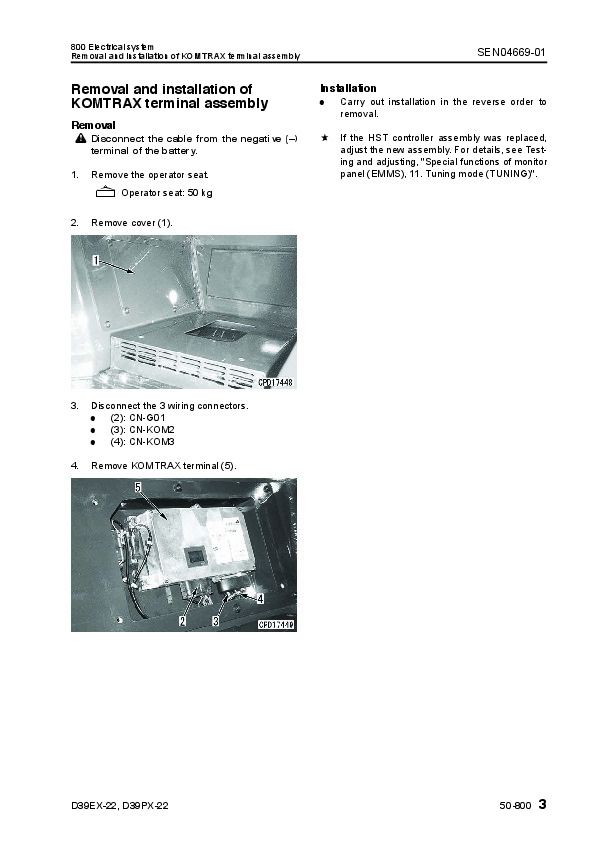
Removal and installation of KOMTRAX terminal assembly...1901
90 Diagrams and drawings...0
100 Hydraulic diagrams and drawings...1903
Work equipment hydraulic circuit diagram...1905
200 Electrical diagrams and drawings...1908
Electrical circuit diagram...1910
Cab electrical circuit diagram...1915
Air conditioner circuit diagram...1918
Connector list and stereogram...1919
Komatsu Bulldozers D39EX,PX Repair Service Manuals


