Mercedes-Benz E63/E63 AMG 2007-2016 Workshop Repair & Service Manual
Catalog:
Model:
Complete workshop manual contains service, maintenance, and troubleshooting information for the 2007-2016 Mercedes-Benz E63, E63 AMG. Diagnostic and repair procedures are covered in great detail to repair, maintain, rebuild, refurbish or restore your vehicle like a professional mechanic in local service/repair workshop. This cost-effective quality manual is 100% complete and intact as should be without any missing pages. It is the same factory shop manual used by dealers that guaranteed to be fully functional to save your precious time.
This manual for 2007-2016 Mercedes-Benz E63, E63 AMG is divided into different sections. Each section covers a specific component or system and, in addition to the standard service procedures, includes disassembling, inspecting, and assembling instructions. A table of contents is placed at the beginning of each section. Pages are easily found by category, and each page is expandable for great detail. It is in the cross-platform PDF document format so that it works like a charm on all kinds of devices. You do not need to be skilled with a computer to use the manual.
EXCERPT:
2008-09 ENGINE Fuel System - E63 (211.077)
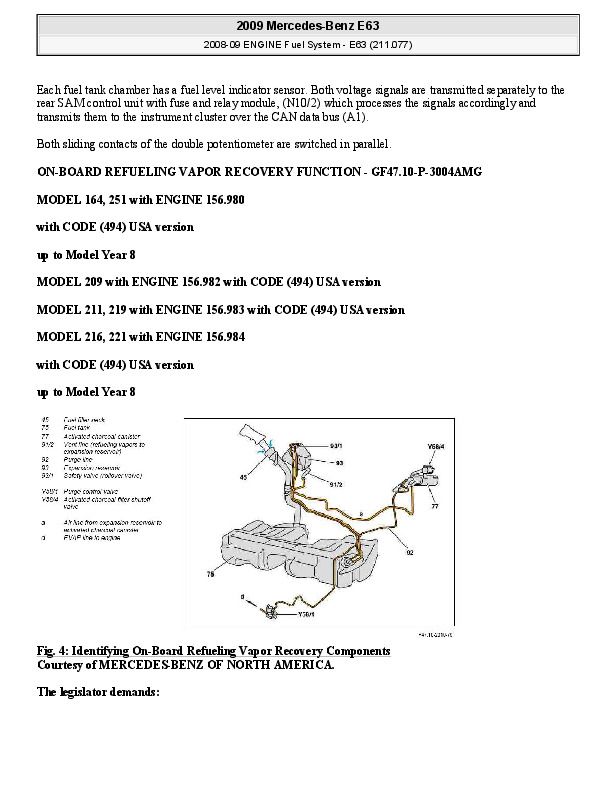
GENERAL INFORMATION
GENERAL NOTES: PASSENGER CARS: FUEL SYSTEM - AH47.00-Z-9999AZ
MODEL all
BASIC KNOWLEDGE
COMPONENT DESCRIPTION FOR THE FUEL TANK - GF47.10-P-2000AT
MODEL 211 with ENGINE 156.983
MODEL 219 with ENGINE 156.983
Fig. 1: Identifying Fuel Tank Components
Location
The saddle-shaped fuel tank with a fill quantity of around 80 liters is located on the underbody in front of the rear axle.
Design
The fuel tank is made of double-layer plastic. Due to the "U"-shaped cut-out, the fuel tank is divided into two interconnected chambers.
Aeration and venting of the fuel tank takes place via the expansion reservoir with the upwards pointing rollover valve.
The rollover valves closes off the ventilation system in the event of an accident to prevent fuel leaking from the tank.
Both fuel pumps are installed in the fuel feed module.
Each fuel tank chamber contains a fuel level indicator for detection of the fuel level.
Emptying
The fuel tank has no outlet valves. It emptying takes place through fuel pumps via the fuel line in the engine compartment or via a corresponding air extractor system.
Function
Fuel supply is controlled and monitored by the ME-SFI [ME] control unit (N3/10) and the left and right fuel pump control units (N118/3, N118/4). The fuel pressure is regulated to be variable from between 4 and 5.5 bar depending on the power requirements.
A fuel strainer is installed at the bottom in the fuel delivery module at the feed to the respective fuel pump.
Fuel pumps draw the fuel at the bottom out of the fuel feed module and deliver it through fuel filter with pressure limiting valve to the fuel injection valve (Y62) on the fuel manifold (single-line system). In doing so, the fuel pressure is limited by the pressure limiting valve to approx. 6.0 bar.
A junction in the fuel line upstream of the fuel filter provides the suction jet pump in the left fuel tank chamber with part of the flow the fuel feed. The suction jet pump delivers the fuel out of the left fuel tank chamber into the fuel feed module (right fuel tank chamber).
The housing of the fuel delivery module serves as a swirl pot. The swirl pot prevents the fuel pump from drawing air while cornering with a low level of fuel in the fuel tank.
COMPONENT DESCRIPTION FOR THE FUEL LEVEL SENSOR - GF47.10-P-2010AMG
MODEL 164, 251 with ENGINE 156.980 up to Model Year 8
MODEL 209 with ENGINE 156.982
MODEL 211, 219 with ENGINE 156.983
MODEL 216, 221 with ENGINE 156.984 up to Model Year 8
Location except model 216, 221 (shown on fuel tank model 164)
Fig. 2: Locating Fuel Level Sensors - Except Model 216, 221
Each chamber of fuel tank contains a fuel gage sensor.
Location on model 216, 221
...
Accessories...1
Anti Theft Systems...1
Defogger Systems...14
Instrument Panel...21
Keyless Entry System...32
Keyless Entry Systems - C230, C280, CLK320, E300, E320 & E430...32
Keyless Entry Systems - C230, C280, CLK320, E300, E320, E430, E500, CL500 & CL600...60
Pneumatic & Power Door Lock Systems...69
Power Mirror/Steering Column Adjustment Systems...104
Power Seats...121
Power Windows...151
Power Window & Sun Roof Systems...151
Power Window & Sun Roof Systems - E Class...179
Steering Column Switches...239
Air Bag Restraint System...247
Brake Systems...273
Anti-Lock Brake System...273
Disc & Drum...374
Drivelines...395
Axle Shafts - Rear...395
Differential...401
Electrical Systems...412
Electrical Component Locator...412
Fuses & Circuit Breakers...468
E300, E320 & E420...468
E300, E320, E420 & E430...486
E300, E320 & E420...506
Generator & Regulator...525
Starter...528
System Wiring Diagrams...540
Engine Mechanical...627
Engine Cooling Specifications...627
Drive Belt Routing...638
Drive Belt Routing...638
Drive Belt Routing...656
Engine Cooling Fan...661
Engine...676
Starter...711
Engine Performance...723
On-Vehicle Adjustments...723
Emission Applications...728
Introduction...731
Removal, Overhaul & Installation...736
Sensor Operating Range Charts...805
Service & Adjustment Specifications...807
System-Component Tests...815
System & Component Testing - Gasoline...815
System & Component Testing - Gasoline...816
Self-Diagnostics - Gasoline - Engine 119...821
Trouble Shooting - No Codes - Gasoline...900
Theory & Operation...901
Vacuum Diagrams...917
Wiring Diagrams...921
General Information...928
Abbreviations...928
Air Bag Deactivation Procedures...953
Air Bag Deactivation Procedures Domestic...953
Air Bag Deactivation Procedures Imports...978
Anti-Lock Brake Safety Precautions...1038
Canadian-To-U.S. Model Reference Tables...1039
Clutch Trouble Shooting...1042
Computer Relearn Procedures...1044
Drive Axle Noise Diagnosis...1046
Electrical...1049
Electrostatic Discharge (ESD) Warning - Basic Information...1058
Engine Overhaul Procedures...1060
Engine Performance Diagnostic Routine Outline...1103
Engine Performance Safety Precautions...1104
Engine Performance Trouble Shooting...1105
English-Metric Conversion Chart...1109
Gear Tooth Contact Patterns...1114
General Cooling System Service...1116
How To Use The Engine Performance Section - 1989 & Newer Models...1119
Manual Transmission Trouble Shooting...1123
OBD-II Vehicles - OBD-II Readiness Monitors...1125
Symptom Check List Worksheets...1187
Traction Control, 4WD & AWD Identification & Disable Procedures - All Models...1201
Trouble Shooting - Basic Procedures...1273
Uniform Inspection and Communication Standards - Brake Systems...1329
Uniform Inspection and Communication Standards - Drive Train & Transmission...1364
Uniform Inspection and Communication Standards - Electrical Systems...1407
Uniform Inspection and Communication Standards - Engine Performance & Maintenence...1463
Waveforms - Injector Pattern Tutorial...1574
Wheel Alignment Theory & Operation...1607
HVAC...1613
A/C Compressor Refrigerant Oil Checking...1613
AC Compressor Servicing...1616
AC Heater System Automatic...1620
AC System General Servicing...1649
AC System Specifications...1654
Cabin Air Filter...1655
Maintenance...1661
Cabin Air Filter...1661
Maintenance Reminder Light Reset Procedure...1667
Maintenence Information...1685
Steering Systems...1695
Electronic Power Steering - 129, 140 & 210 Chassis...1695
Steering Columns...1735
Suspensions...1750
Front Suspension...1750
Rear Suspension...1762
Wheel Alignment Specifications & Procedures...1773
Transmissions...1792
W5A580/722.6 Series Diagnosis...1792
W5A580/722.6 Series Overhaul...1835
Removal & Installation - Mercedes-Benz 722.6 Series...1886
AT Servicing...1889
Hydraulic Diagrams...1894
Shift Interlock System...1897
Transmission Oil Pan Gasket ID...1939
...


