Bobcat T320 Compact Track Loader Factory Service & Shop Manual
Catalog:
Model:
Complete workshop repair service manual with electrical wiring diagrams for Bobcat T320 Compact Track Loader. It's the same service manual used by dealers that guaranteed to be fully functional and intact without any missing page.
This Bobcat T320 Compact Track Loader service repair manual (including maintenance, overhaul, disassembling & assembling, adjustment, tune-up, operation, inspecting, diagnostic & troubleshooting…) is divided into different sections. Each section covers a specific component or system with detailed illustrations. A table of contents is placed at the beginning of each section. Pages are easily found by category, and each page is expandable for great detail. The printer-ready PDF documents work like a charm on all kinds of devices.
6986557 (3-08) - T320 Compact Track Loader Operation & Maintenance Manual.pdf
6986558 (3-09) - T320 Compact Track Loader Service Manual.pdf
6986606 (11-10) - T320 Compact Track Loader Operation & Maintenance Manual.pdf
6987046 (5-11) - T320 Compact Track Loader Service Manual.pdf
6987046 (6-10) - T320 Compact Track Loader Service Manual.pdf
EXCERPT:
CONTENTS
FOREWORD. . . II
SAFETY INSTRUCTIONS . . . . . . . . V
FIRE PREVENTION . . . . VII
SERIAL NUMBER LOCATIONS . . . . IX
DELIVERY REPORT. . . . . X
LOADER IDENTIFICATION . . . . . . .XI
SAFETY & MAINTENANCE . . . . 10-01
HYDRAULIC SYSTEM . . . . . . . . 20-01
HYDROSTATIC SYSTEM . . . . . . 30-01
DRIVE SYSTEM . . . . . 40-01
MAINFRAME. . . . . . . . 50-01
ELECTRICAL SYSTEM & ANALYSIS. . . . . 60-01
ENGINE SERVICE . . . 70-01
HEATING, VENTILATION, AIR CONDITIONING . . . . 80-01
SPECIFICATIONS. . . . . . . . . SPEC-01
…
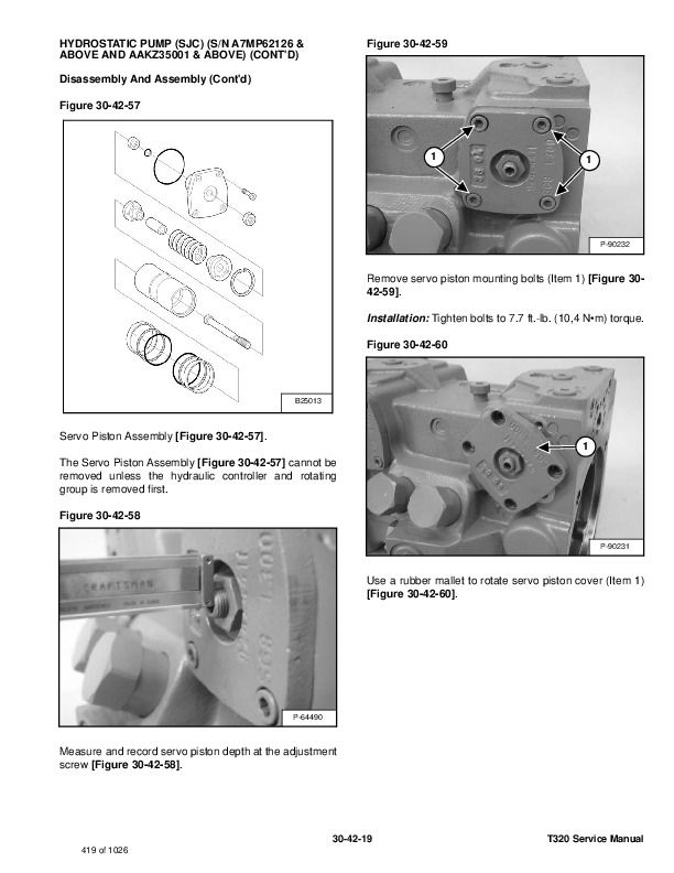
HYDROSTATIC PUMP (SJC) (S/N A7MP62126 & ABOVE AND AAKZ35001 & ABOVE) (CONT'D)
Disassembly And Assembly (Cont'd)
Figure 30-42-33
Figure 30-42-34
Figure 30-42-35
Figure 30-42-36
Assembly: Align the timing pin (Item 1) [Figure 30-42-33] and [Figure 30-42-34] in the case housing with the
notch (Item 1) [Figure 30-42-35] and [Figure 30-42-36] that does not go through the valve plate.
Align the shoulder of the roller bearing (Item 2) [Figure 30-42-33] and [Figure 30-42-34] with the beveled edge on the valve plate (Item 2) [Figure 30-42-35] and [Figure 30-42-36].
NOTE: Valve plate should sit FLUSH with the case housing when properly installed.
…


