Doosan DX300LC Crawler Excavator Factory Service & Shop Manual
Catalog:
Model:
Complete workshop repair service manual with electrical wiring diagrams for Doosan DX300LC Crawler Excavator. It's the same service manual used by dealers that guaranteed to be fully functional and intact without any missing page.
This Doosan DX300LC Crawler Excavator service & repair manual (including maintenance, overhaul, disassembling & assembling, adjustment, tune-up, operation, inspecting, diagnostic & troubleshooting…) is divided into different sections. Each section covers a specific component or system with detailed illustrations. A table of contents is placed at the beginning of each section. Pages are easily found by category, and each page is expandable for great detail. The printer-ready PDF documents work like a charm on all kinds of devices.
"K1006408E - DX300LC Operation & Maintenance Manual.pdf"
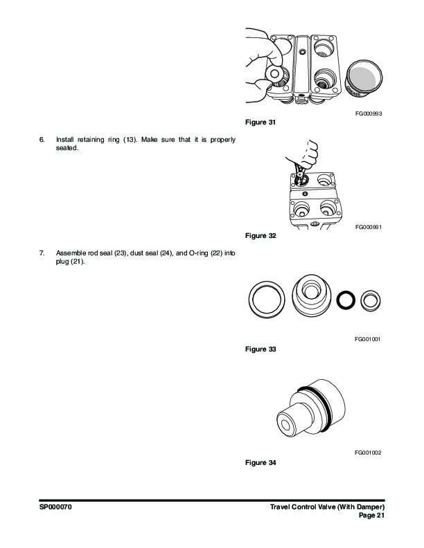
"DX300 - Electrical Schematic.pdf"
“K1006409E - DX300LC Shop Manual.pdf”
"DX300 - Hydraulic Schematic.pdf"
Doosan DX300LC Crawler Excavator Shop Manual
K1006409E; Serial Number 5001 and Up; 818 pages
TABLE OF CONTENTS
Safety
Track Excavator Safety
Specifications
Specification for DX300LC
General Maintenance
General Maintenance Procedures
Standard Torques
Upper Structure
Cabin
Counterweight
Fuel Tank
Fuel Transfer Pump
Swing Bearing
Swing Reduction Gear
Lower Structure and Chassis
Track Assembly
Air Conditioner
Engine and Drive Train
Drive Coupling (Main Pump)
Hydraulics
Hydraulic System Troubleshooting, Testing and Adjustment
Accumulator
Center Joint (Swivel)
Cylinders
Swing Motor
Travel Motor
Gear Pump
Main Control Valve
Hydraulic Schematic (DX300LC)
Axial Piston Pump
Remote Control Valve (Work Lever / Joystick)
Travel Control Valve (With Damper)
Electrical System
Electrical System
Electrical Schematic (DX300LC)
Attachments
Boom and Arm
Bucket
…
EXCERPT:
"Compound Operation"
"Travel Compound Operation"
"In the event of operating another function when the traveling left or right (when advancing, backing, or pivot turning) or operating for travel operation during the operation other than traveling, the oil supplied from the port (PP) is cut off from the tank passage (Ta) in the signal land part of the section other than the travel shifted from the land (Lc4), (Lc7), (Rc3), and (Rc5), and the pressure of the signal passage is increased to the relief set pressure of the oil origin for signal."
"Due to the increase of the signal pressure, the spool before traveling is shifted to cause an increase of pressure in ports (PT and PA)."
"When the straight travel spool is shifted, the oil supplied from port (P1) flows to travel (section1) from neutral passage (L1) while oil supplied to port (P2) flows into travel (section 6) after passing through passage (2), straight travel spool head, and neutral passage (R1) flowing into the parallel passage (L3) after passing the straight travel spool head, and passage (1)."
"In the event that load pressure of section other than traveling is higher than the travel (Section 6) load pressure, some of the oil supplied from port (P2) pushes and opens poppet (S6-2), and it merged into the passage (S6-1) after passing the orifice of the poppet."
"The operation is made by oil supplied from travel (Section 1 and"
"6) port (P1), and work device other than traveling is operated by the oil supplied from the port (P2), and projection is prevented"
"when operating with travel operation and other work device."
…
DX300 - Electrical Schematic......2
DX300 - Hydraulic Schematic......3
K1006408E - DX300LC Operation & Maintenance Manual......4
Safety......10
To the Operator of a DOOSAN Daewoo Excavator......10
Learn the Signal Words Used with the Safety Alert Symbol......12
Location of Safety Labels......14
1. Warnings for Operation, Inspection and Maintenance (19000688, 19000092)......16
2. Warnings for High Voltage (19000689, 19000096)......16
3. Warnings When Opening a Front Window (21903388, 19000093)......17
4. Warnings for a Highpressure Cylinder (19000122)......17
5. Warnings When Adjusting Track Tension (21903386A, 19000521)......18
6. Warnings for Leaving Operator's Seat (19000693, 19000094)......18
7. Warnings for Batteries Maintenance (21902533A, 19000100)......19
8. Warnings for High Temperature Hydraulic Oil (19000691, 19000097)......19
9. Warnings for Hot Coolant (19000692, 19000097)......20
10. Warnings for Handling an Accumulator (19000703, 19000099)......20
11. Warnings for Rotating Parts (19000694, 19000095, 19000557)......21
12. Warning Tag Used When Inspection and Maintenance (19000695, 19000098)......21
13. Warning for a Hot Surface (19000648A)......22
14. Caution for Hood (19000522)......22
15. Keep Out of the Swing Area (21903379, K1008571)......23
16. Warnings for Front Attachments (19000652)......23
Summary of Safety Precautions for Lifting in Digging Mode......24
Unauthorized Modifications......25
General Hazard Information......25
Safety Rules......25
Safety Features......25
Inside Operator's Compartment......26
Clothing and Personal Protective Items......26
Breathing Masks, Ear Protection May Be Required......27
Vibration Level Information......27
Recommendations for Limiting Vibrations......27
Mounting and Dismounting......28
Fuel, Oil and Hydraulic Fluid Fire Hazards......29
Precautions When Handling Fluids at High Temperature......29
Asbestos Dust Hazard Prevention......30
Injury from Work Equipment......30
Fire Extinguisher and First Aid Kit......30
Protection from Falling or Flying Objects......31
Attachment Precautions......32
Accumulator......32
Indoor Ventilation......32
Emergency Exit......33
Before Starting Engine......34
Work Site Precautions......34
Checks Before Starting Engine......35
Engine Starting......35
Before Operating Machine......36
Machine Operation......38
When Swinging or Changing Direction of Travel......38
Travel Precautions......39
Traveling on Slopes......40
Prohibited Operations......40
Precautions for Operation......41
Avoid High Voltage Cables......42
Protecting Cabin from Falling Object (Optional)......42
Operate Carefully on Snow, Ice and in Very Cold Temperatures......43
Operations on Slopes......43
Parking Machine......44
Never Let Anyone Ride on Attachment......44
Maintenance......45
Warning Tag......45
Clean Before Inspection or Maintenance......45
Proper Tools......46
Use of Lighting......46
Fire Prevention and Explosion Prevention......46
Burn Prevention......47
Welding Repairs......47
Warning for Counterweight and Front Attachment Removal......49
Precautions for Removal, Installation, and Storage of Attachments......49
Precautions When Working on Machine......50
Lock Inspection Covers......50
Crushing Prevention and Cutting Prevention......50
Track Tension Adjustments Require Caution......51
Supports and Blocking for Work Equipment......51
Action When Abnormality Is Found During Inspection......51
Precautions with Highpressure Lines, Tubes and Hoses......52
Waste Materials......53
Battery......54
Battery Hazard Prevention......54
Boost Starting or Charging Engine Batteries......55
Towing......56
Precautions When Towing......56
Shipping and Transportation......57
Obey State and Local OvertheRoad Regulations......57
Excavator Rated Lift Capacity Tables......58
Operating Controls......64
Component Locations......67
Operator's Area......69
Operational Controls and Panels......71
1. Starter Switch......73
2. Engine Speed Control Dial......73
3. Quick Clamp Switch (Optional)......74
4. Auxiliary Mode Switch......74
5. Engine Emergency Stop Switch......74
6. Audio Control Panel......75
7. Travel Speed Selector Switch......76
8. Light Switch......76
9. Breaker / Boost / Shear Selector Switch......77
10. Cabin Work Light Switch (Optional)......77
11. Warning Light Switch (Optional)......77
12. Lower Wiper Switch (Optional)......78
13. Heater and Air Conditioner Control Panel......78
14. Wiper Switch Panel......78
15. Cigarette Lighter......80
16. Power Socket for 12 Volt......80
17. Travel/Swing Alarm Switch (Optional)......80
18. Overload Warning Switch (Optional)......81
19. Fuel Heater Switch (Optional)......81
20. Seat Warmer Switch (Optional)......81
21. Horn Button (Lefthand Work Lever)......82
22. Rotating Buttons......82
23. Booster Button (Righthand Work Lever)......82
24. Shear Buttons......83
25. Instrument Panel......83
26. Safety Lever......83
27. Photo Sensor......84
Instrument Panel......85
Functional check......86
Password Activated......86
1. Fuel Gauge......87
2. Engine Coolant Temperature Gauge......87
3. Hydraulic Oil Temperature Gauge......88
4. Multifunction Gauge and Graphic Information Area......88
5. Digital Clock......88
6. Hour Meter......89
7. Charge Warning Light......89
8. Engine Oil Pressure Warning Light......89
9. Engine Coolant Temperature Warning Light......90
10. Engine Check Warning Light......90
11. Preheating Indicator Light......91
12. Work Light Indicator Light......91
Multifunction Gauge and Graphic Information......92
Communication Indicator......92
Communication Error Warning......93
Engine Speed......93
Battery Voltage......93
Front Hydraulic Pump Pressure......94
Rear Hydraulic Pump Pressure......94
Abnormal State Warning Symbols......94
Mode Selector Buttons......97
1. Power Mode Selector Button......97
2. Trenching Mode Selector Button......98
3. Auto Idle Selector Button......98
4. Flow Control Button......98
Setting Main Menu......99
1. Up Arrow Button......99
2. Down Arrow Button......100
3. Display Selector Button (ESC Escape)......100
4. SelectionButton......100
Display Selection and Escaping......101
Main Menu......101
Language......102
Set Clock......102
Filter / Oil Info......103
Adjust Display......105
Set Password (Lock and Unlock)......106
Flow Control......108
Adjusting Flow Rate......109
Escape......109
Operation Selection Display......110
Power Boost Selection......110
Breaker Selection......110
Shear Selection......110
Overload Alarm Selection (Optional)......111
Quick Clamp Operation Selection (Optional)......111
Heater and Air Conditioner Control Panel......112
Location of Controls and Vents......112
Control Panel......113
Memory Function......117
Additional Operating Instructions......117
Stereo......118
Stereo......118
CD Player (Optional)......119
Miscellaneous Electrical Devices......120
Cabin Light......120
Pilot Cutoff Switch......120
Circuit Breaker......120
Fusible Link......121
Fuse Boxes......121
Seat Adjustment......122
1. Forward / Backward Adjustment......122
2. Seat Tilt and Height Adjustment......122
3. Suspension Adjustment......122
4. Reclining Position Adjustment......123
5. Armrest Angle Adjustment......123
6. Lumbar Support Adjustment......123
7. Headrest......123
8. Seat Belt......123
9. Seat Backpocket......124
10. Left and Right Control Stand Adjustment......124
11. Left and Right Control Stand Height Adjustment......124
12. Air Suspension Seat (Optional)......125
13. Heating the Operator's Seat (Optional)......125
Ceiling Cover......126
Opening the Ceiling Cover......126
Closing the Ceiling Cover......126
Front Windows......127
Front Upper Window......127
Front Bottom Window......128
Door Side Latch......129
Cabin Storage Compartments......130
Ashtray......130
Sun Visor......131
Hanger......131
Cup Holder......132
Door Window Holder......132
Emergency Glass Breaking Tool......132
Miscellaneous Access Covers and Doors......133
Side Door......133
Battery Box Door......133
Engine Cover......133
Operation......134
To Handle a New Excavator......134
Lubrication and Filters......135
Starting and Stopping the Engine......135
Inspection Before Starting Engine......135
Operational Checks Before Starting Engine......136
Engine Start......137
Cold Weather Starting......139
Starting Engine With a Booster Cable......140
Hydraulic System Warmup......142
Hydraulic System Warmup – Cold Weather......143
Engine Shut Down......144
Check and Confirmation After Stopping Engine......145
Safety Lever......146
Travel......147
Automatic Travel Speed Control......147
Travel Control Lever Operation......149
General Travel Instructions......150
Operating Instructions......153
Engine Speed Control......153
Mode Selection......153
Work Levers (Joysticks) (ISO Style)......156
Operating Precautions......157
Working in Water......161
Parking Excavator......162
Towing Procedure......163
Hydraulic Breaker......164
Selection of Hydraulic Breaker......164
Hydraulic Hoses and Tubing for Breaker......164
Hydraulic Breaker Operation......164
Hydraulic Oil and Filter Service Intervals......168
Adjusting the Pump Flow......169
Shear Pedal Valve (Optional)......170
Rotating Pedal Valve (Optional)......171
Operating Techniques......172
Lifting......172
Operation Under Unusual Conditions......174
Operation In Extreme Cold......174
Operation in Extreme Heat......175
Operation in Dusty or Sandy Areas......176
Operation in Rainy or Humid Conditions......176
Operation in Salt Water Areas......177
Operation at High Altitudes......177
Inspection, Maintenance and Adjustment......178
Preventive Maintenance......178
Product Identification Number (P. I. N.) Location......179
Component Serial Numbers......179
Safety Precautions......180
Preliminary Work Machine Setup for Maintenance......181
Table of Recommended Lubricants......183
Fluid Capacities......185
Lubrication and Service Chart......185
Maintenance Intervals......189
10 Hour / Daily Service......191
Grease Boom, Arm and Front Attachment Pins (for first 100 hours)......191
Check Engine Oil Level......191
Check Level of Hydraulic Oil Tank......192
Check for Leaks in Hydraulic System......193
Check Fuel Level......193
Check for Leaks in Fuel System......194
Check Fuel Prefilter and Drain Water As Required......194
Check Oil Level of Swing Reduction Device......196
Clean Dust Net in Front of Oil Cooler and Intercooler......197
Check Cooling System and Refill As Required......197
Check Level of Window Washer Liquid......198
Inspect the Bucket Teeth and Side Cutters for Signs of Wear......198
Inspect Engine Fan Blade......199
Check Air Intake System......199
Inspect Seat Belt for Proper Operation......199
Inspect the Structure for Cracks and Faulty Welds......200
Check the Operation of All Switches......200
Check the Operation of All Exterior Lights, Horn and Control Console Indicator and Monitor Lights......200
Start Engine, Check Starting Ability, and Observe Exhaust Color at Startup and at Normal Operati.......200
Check Operation of All Controls......201
50 Hour / Weekly Service......202
Perform All Daily Service Checks......202
Grease Arm and Front Attachment Pins......202
Grease Swing Bearing......203
Drain Water and Sediment from Fuel Tank......204
Check Engine Fan Belt for Cracks, Wear and Correct Tension (After First 50 Hours)......204
Change Engine Oil and Filter (After First 50 Hours)......204
Inspect the Track Assemblies for Proper Tension and Loose, Worn or Damaged Parts (Links, Shoes, R.......204
250 Hour / Monthly Service......205
Perform All Daily and 50 Hour Service Checks......205
Change Swing Reduction Device Oil (Drain and Refill After First 250 Hours)......205
Grease Arm and Front Attachment Pins......206
Check Engine Fan Belt Tension......208
Check Engine Fan Belt Wear......208
Check Oil Level in Travel Reduction Device (One on Each Side of Unit)......209
Change Breaker Filter Element (Optional)......210
Change Oil in Travel Reduction Device (One on Each Side of Unit) (After First 250 Hours)......210
Replace Hydraulic Oil Return Filter (After First 250 Hours)......210
Change Pilot Filter (After First 250 Hours)......210
Inspect Pins and Bushings of the Front End Attachments for Signs of Wear......211
Check Fluid Levels in Batteries and Battery Charge Levels......211
Inspect for Any Loose or Missing Nuts and Bolts......211
Inspect Fuel System Hose Clamps......211
500 Hour / 3 Month Service......212
Perform All Daily, 50 and 250 Hour Service Checks......212
Grease Swing Gear and Pinion......212
Change Engine Oil and Filter......213
Clean AirConditioning Outer Filter......214
Check and Clean AirConditioning Inner Filter......215
Clean Radiator, Oil Cooler, Intercooler, Fuel Cooler and Air Conditioner Condenser Core......216
Clean Outer Filter of Air Cleaner......217
Change of Fuel Prefilter......218
Change Fuel Filter......219
1,000 Hour / 6 Month Service......221
Perform All Daily, 50, 250 and 500 Hour Service Checks......221
Grease Swing Reduction Device......221
Change Pilot Filter......223
Change Oil in Travel Reduction Device (One on Each Side of Unit)......224
Change AirConditioning Outer Filter......225
Check Air Conditioner Refrigerant......226
Check and Adjust Engine **......227
2,000 Hour / Yearly Service......228
Perform All Daily, 50, 250, 500 and 1,000 Hour Service Checks......228
Change Swing Reduction Device Oil......228
Replace Outer and Inner Air Cleaner Elements......229
Change Radiator Coolant......230
Hydraulic Oil Exchange and Suction Strainer Cleaning......231
Check Alternator and Starter**......233
Check All Rubber Antivibration Shock Mounts......233
Perform and Record the Results of the Cycle Time Tests......233
Inspect Machine to Check for Cracked or Broken Welds or other Structural Damage......233
Check, Adjust Valve Clearance **......233
Check Head Bolt Torques......233
4,000 Hour / Biennial Service......234
Major Parts Periodic Replacement......234
12,000 Hour / Six Year Service......235
Hose Inservice Lifetime Limit (European Standard ISO8331 and EN982CEN)......235
AirConditioning System......236
Check Control Panel......236
Check Air Conditioner Hoses......236
Check Condenser......236
Check Magnetic Clutch......236
Check Belt Tension......236
Bolt and Nut Inspection......237
Transportation......266
Loading and Unloading......266
Warning for Counterweight and Front Attachment Removal......266
Lifting With Sling......270
Troubleshooting......272
Electrical System......272
Engine......273
Hydraulic System......274
Swing System......275
Travel System......276
Specification......278
Standard Specification......278
Overall Dimensions......279
Working Range......280
Approximate Weight of Workload Materials......281
Index......284
K1006409E - DX300LC Shop Manual......289
Table Of Contents......293
Safety......295
Track Excavator Safety......297
Safety Precautions......301
Applicable Models......301
To the Operator of a DOOSAN Daewoo Excavator......302
Learn the Signal Words Used with the Safety Alert Symbol......304
General Safety Essentials......306
Accessory Applications......306
Lifting Capacity Rating Configuration......306
Location of Safety Labels......307
Summary of Safety Precautions for Lifting in Digging Mode......308
Unauthorized Modifications......309
General Hazard Information......309
Safety Rules......309
Safety Features......309
Inside Operator's Compartment......310
Clothing and Personal Protective Items......310
Breathing Masks, Ear Protection May Be Required......311
Vibration Level Information......311
Recommendations for Limiting Vibrations......311
Mounting and Dismounting......312
Fuel, Oil and Hydraulic Fluid Fire Hazards......313
Precautions When Handling Fluids at High Temperature......313
Asbestos Dust Hazard Prevention......314
Injury from Work Equipment......314
Fire Extinguisher and First Aid Kit......314
Protection from Falling or Flying Objects......315
Attachment Precautions......316
Accumulator......316
Indoor Ventilation......316
Emergency Exit......317
Before Starting Engine......318
Work Site Precautions......318
Checks Before Starting Engine......319
Engine Starting......319
Before Operating Machine......320
Machine Operation......322
When Swinging or Changing Direction of Travel......322
Travel Precautions......323
Traveling on Slopes......324
Prohibited Operations......324
Precautions for Operation......325
Avoid High Voltage Cables......326
Protecting Cabin from Falling Object (Optional)......326
Operate Carefully on Snow, Ice and in Very Cold Temperatures......327
Operations on Slopes......327
Parking Machine......328
Never Let Anyone Ride on Attachment......328
Maintenance......329
Warning Tag......329
Clean Before Inspection or Maintenance......329
Proper Tools......330
Use of Lighting......330
Fire Prevention and Explosion Prevention......330
Burn Prevention......331
Welding Repairs......331
Treatment for Electrical Welding to the Body Structure......332
Warning for Counterweight and Front Attachment Removal......333
Precautions for Removal, Installation, and Storage of Attachments......333
Precautions When Working on Machine......334
Lock Inspection Covers......334
Crushing Prevention and Cutting Prevention......334
Track Tension Adjustments Require Caution......335
Supports and Blocking for Work Equipment......335
Action When Abnormality Is Found During Inspection......335
Precautions with High-pressure Lines, Tubes and Hoses......336
Waste Materials......337
Battery......338
Battery Hazard Prevention......338
Boost Starting or Charging Engine Batteries......339
Towing......340
Precautions When Towing......340
Shipping and Transportation......341
Obey State and Local Over-the-Road Regulations......341
Lifting With Sling......341
Specifications......343
Specification for DX300LC......345
Safety Precautions......349
Applicable Models......349
General Description......351
Component Locations......352
General Dimensions......354
Working Range......356
General Specifications......358
Engine Performance Curves (Per DIN6270 Standard)......360
Approximate Weight of Workload Materials......362
Performance Tests......364
Excavator Performance Standards......365
Test Conditions......365
Travel Speed and Travel Motor Balance (Steering Deviation) Tests......365
Speed Test......365
Travel Deviation......367
Swing Speed and Deceleration Force Test......367
Swing Speed Test......367
Swing Deceleration Force Test......368
Cylinder Performance Tests......369
Boom Cylinders Test......369
Arm Cylinder Test......369
Bucket Cylinder Test......369
Hydraulic Cylinder Natural Drop Test......369
Travel Motor Jack-up Test......369
General Maintenance......371
General Maintenance Procedures......373
Safety Precautions......377
Applicable Models......377
Welding Precautions and Guidelines......378
Hydraulic System - General Precautions......379
Maintenance Service and Repair Procedure......381
General Precautions......381
Hydraulic System Cleanliness and Oil Leaks......382
Maintenance Precautions for Hydraulic System Service......382
Oil Leakage Precautions......383
Cleaning and Inspection......384
General Guidelines......384
Bearing inspection......385
Normal Bearing......386
Bent Cage......386
Galling......387
Abrasive Step Wear......387
Etching......388
Misalignment......388
Indentations......388
Fatigue Spalling......389
Brinelling......389
Cage Wear......389
Abrasive Roller Wear......390
Cracked Inner Race......390
Smears......390
Frettage......391
Heat Discoloration......391
Stain Discoloration......391
Standard Torques......393
Safety Precautions......397
Applicable Models......397
Torque Values for Standard Metric Fasteners......398
Torque Values for Standard U.S. Fasteners......399
Type 8 Phosphate Coated Hardware......401
Torque Values for Hose Clamps......402
Torque Values for Split Flanges......403
Torque Wrench Extension Tools......404
Torque Multiplication......404
Other Uses for Torque Wrench Extension Tools......405
Tightening Torque Specifications (Metric)......405
I. "Loctite" Fastener Adhesives......407
II. "Loctite" Pipe Thread Sealant......407
III. "Loctite" gasket/flange sealer......407
IV. "Loctite" retaining compounds......408
V. "Loctite" Adhesives......408
Upper Structure......409
Cabin......411
Safety Precautions......415
Applicable Models......415
Removal......416
Installation......418
Counterweight......421
Safety Precautions......425
Applicable Models......425
General......426
Warning for Counterweight and Front Attachment Removal......426
Removal......428
Installation......430
Fuel Tank......431
Safety Precautions......435
Applicable Models......435
General Description......436
Parts List......436
Specifications......437
Removal......438
Installation......443
Start-up Procedures......446
Fuel Transfer Pump......447
Safety Precautions......451
Applicable Models......451
General Description......452
Theory of Operation......452
Troubleshooting......453
Replacement of Rotor and Vane......453
Replacement of Rear Cover......454
Replacement of Armature......454
Swing Bearing......455
Safety Precautions......459
Applicable Models......459
Swing Bearing Maintenance......460
Operating Recommendation......460
Measuring Swing Bearing Axial Play......460
Measuring Bearing Lateral Play......460
Swing Bearing Basic Operation......461
Rebuilding Swing Bearing......461
Swing Reduction Gear......463
Safety Precautions......467
Applicable Models......467
General Description......469
Theory of Operation......469
Parts List......470
Specifications......471
Troubleshooting, Testing and Adjustment......472
Removal......473
Disassembly......474
Cleaning and Inspection (Wear Limits and Tolerances)......483
Reassembly......484
Shaft and S/R Bearing Heatfit......484
Assembly of Carrier Subassemblies......484
Cleaning Carrier......484
Cleaning Planet Gear......484
Assembly of No. 1 Carrier......484
Assembly of No. 2 Carrier......487
Assembly of Main Case......490
Cleaning Casing and Other Parts......490
Assembly of Shaft and Pinion......490
Assembly of Seal and Bearing......495
Assembly of Ring Gear......499
Assembly of Carrier......501
Assembly of Motor......506
Add Gear Oil......506
Assembly of Motor......506
Supply of Grease......508
Installation......510
Startup Procedures......511
Lower Structure and Chassis......513
Track Assembly......515
Safety Precautions......519
Applicable Models......519
General Description......520
Track Tension......520
Cleaning and Inspection (Wear Limits and Tolerances)......523
Track Shoe......524
Lower Roller......526
Upper Roller......527
Front Idler......528
Track Shoes and Links......529
Track Removal......529
Track Installation......530
Front Idler Roller......532
Parts List......532
Front Idler Roller Disassembly......533
Front Idler Roller Reassembly......534
Lower Roller......536
Parts List......536
Lower Roller Removal......537
Lower Roller Disassembly......537
Lower Roller Reassembly......538
Lower Roller Installation......539
Upper Roller......540
Parts List......540
Upper Roller Removal......541
Upper Roller Disassembly......541
Upper Roller Reassembly......543
Track Spring and Track Adjusting Cylinder......544
Parts List......544
Air Conditioner......547
Safety Precautions......551
Applicable Models......551
Air Conditioner System......552
Outline......552
Internal and External Filters......553
How to check Indoor air filter......553
How to check outdoor air filter......553
Air-Conditioning System Layout......555
Air Conditioner/Heater Circuit Diagram......556
Air Conditioner/Heater Unit......557
Air Flow Diagram......557
Door Open by Vent Modes......558
Main Components......558
Actuator - Internal/external air exchange......560
Air Flow Control Module......560
Relay - Blower......561
Relay - A/C......561
Duct Sensor......561
Water Temp Sensor......562
Internal Air Temp Sensor......562
Ambient Air Temperature Sensor......562
Sun Sensor......563
Control Panel......563
Appearance and Terminal Arrangement......563
Terminal Terms......564
Control Logic......564
Self Diagnosis......569
Ambient Temp Display......570
Compressor......571
Receiver Dryer......571
Troubleshooting......572
Refrigerant Pressure Check......572
Weight of R134a Gas Used In Machines......575
Refrigerant System Repairs......576
Refrigerant Safe Handling Procedures......576
Repair and Replacement Procedure......577
Refrigerant Recovery......579
Vacuuming Refrigerant System......579
Leakage Check......580
Refrigerant Charging......581
Inspecting System For Leakage......583
Engine and Drive Train......585
Drive Coupling (Main Pump)......587
Safety Precautions......591
Applicable Models......591
Drive Coupling......592
Installation of Drive Coupling......593
Installation Procedure......593
Hydraulics......595
Hydraulic System Troubleshooting, Testing and Adjustment......597
Safety Precautions......601
Applicable Models......601
Hydraulic System - General Notes......602
Hydraulic Schematic......604
General Notes......604
Operation of Working Components......606
Boom Operating Circuit......606
Boom Up Circuit......606
Boom Down Circuit......606
Arm Operating Circuit......607
Arm Crowd Circuit......607
Arm Dump Circuit......607
Bucket Operating Circuit......608
Bucket Crowd Circuit......608
Bucket Dump Circuit......608
Swing Operating Circuit......608
Right Swing Operating Circuit......609
Left Swing Operating Circuit......609
Swing Relief Valve and Makeup Valve......609
Travel Operating Circuit......609
Forward Travel Circuit......610
Reverse Travel Circuit......610
Procedural Troubleshooting Baseline Recommendations......611
Initial Checks and Tests to Establish Operating Condition of the Excavator......611
Triage Summary......611
Pilot Pressure......613
Adjustment and Testing......613
Power Mode Valve......614
Current Signal and Hydraulic Pressure Adjustments......614
Swing Priority Valve......615
Control Valve Pressure and Current Adjustments......615
Pressure Up Valve......617
Checks and Adjustments......617
Pump Input Power Control......619
Pump Regulator Adjustment......619
Flow Meter and Flow Meter Kit Installation and Testing......623
Installation and Testing Procedure......623
Swing System Troubleshooting......625
Precautions/Initial Checks......625
Swing Relief Valve Checking and Adjustment......625
Troubleshooting – Swing Gearbox......628
Troubleshooting – Hydraulic Problems......629
Troubleshooting – Control Valve......630
Troubleshooting – Travel Control Valve......632
Troubleshooting – Joystick Control Valve......632
Accumulator......635
Safety Precautions......639
Applicable Models......639
General Description......640
Specifications......642
Center Joint (Swivel)......643
Safety Precautions......647
Applicable Models......647
General Description......648
Parts List......649
Troubleshooting, Testing and Adjustment......650
Inspection......650
Testing......650
Disassembly......651
Reassembly......652
Cylinders......653
Safety Precautions......657
Applicable Models......657
General Description......658
Theory of Operation......658
Parts List......659
Special Tools and Materials......661
Piston Nut......661
Piston Jig......662
Steel Bushing Jig......664
Dust Wiper Jig......666
Slipper Seal Jig......668
Slipper Seal Straightening Jig......669
Disassembly......670
Reassembly......675
Swing Motor......679
Safety Precautions......683
Applicable Models......683
General Description......684
Theory of Operation......684
Structure......684
Circuit Diagram......684
Generation of Rotary Power......685
Operation of Relief Valve......686
Operation of Parking Brake......686
Makeup Check Valve......687
Operation of Time Delay Valve......687
External Pilot Pressure: When Pi = 0 (Large Tilt Angle)......687
Operation of Swing Reactionless Valve......687
Parts List......688
Specifications......689
Torques......689
Tools and Materials......690
Tools......690
Troubleshooting, Testing and Adjustment......691
General Precautions......691
How to Check Faults of Hydraulic Motor......691
Troubleshooting......691
Disassembly......693
General Cautions......693
Disassembly......693
Cleaning and Inspection (Wear Limits and Tolerances)......701
Reassembly......702
General Cautions......702
Assembly......702
Assembly of Cylinder Block Assembly Subassembly......705
Assembly of Rear Cover Assembly Subassembly......709
Air Pressure Test......715
Oil Leakage Check......715
Travel Motor......717
Safety Precautions......721
Applicable Models......721
General Description......723
Structure......723
Operation Basics......724
Generation of Rotary Power......724
Operation of Relief Valve......725
Operation of Negative Brake......726
Counterbalance Valve......727
Operation of Swash Plate Control......728
Parts List......730
Specifications......732
Connection Torque......732
Special Tools and Materials......734
Troubleshooting, Testing and Adjustment......735
General Precautions......735
How to Check Faults of Hydraulic Motor......735
Troubleshooting......735
Disassembly......738
General Cautions......738
Disassembly......738
Disassembly of Valve Casing Subassembly......742
Disassembly of Cylinder Subassembly......744
Cleaning and Inspection (Wear Limits and Tolerances)......746
Maintenance Standard......746
Changing Standard of Hydraulic Motor Part......746
Parts Inspection and Inspection Standard of Reduction Gear......748
Reassembly......750
General Cautions......750
Reassembly of Drive Shaft Subassembly......750
Assembly of Valve Casing Subassembly......751
Assembly of Cylinder Subassembly......755
Assembly of Motor Body......757
Gear Pump......763
Safety Precautions......767
Applicable Models......767
Single Gear Pump......768
Disassembly......768
Reassembly......770
Double Gear Pump......774
Disassembly......774
Reassembly......776
Main Control Valve......781
Safety Precautions......785
Applicable Models......785
General Description......787
Theory of Operation......787
When All Spools are in Neutral......787
Single Operation......792
Compound Operation......806
Antidrift Valve......812
Main Relief Valve......813
Overload Relief Valve......814
Low-pressure Relief Valve......816
Parts List......818
Specifications......823
Troubleshooting, Testing and Adjustment......824
Troubleshooting......824
Overall Control Valve......824
Relief Valve......825
Overall Oil Pressure......825
Adjustment of Valves......825
Main Relief Valve......825
Overload Relief Valve......826
Disassembly......827
Caution in Disassembly......827
Disassembly of Main Spool Part......828
Disassembly of Arm 1 Para-turn Spool Part......829
Disassembly of Arm Regeneration Release Valve Part......829
Disassembly of Load Check Valve Part......830
Disassembly of Antidrift Valve Part......831
Disassembly of Relief Valve......832
Disassembly of Option Section Part......832
Disassembly of Other Plugs......832
Disassembly of Valve Housing Bolt......833
Disassembly of Main Relief Valve......834
Disassembly of Overload Relief Valve......835
Instruction of Disassembly and Assembly of Low-pressure Relief Valve......836
Cleaning and Inspection (Wear Limits and Tolerances)......837
Cleaning......837
Inspection......837
Reassembly......838
Caution on Assembly......838
Caution on Handling O-ring......838
Caution on Handling Spool......838
Method of Painting the Adhesives (screw part and arm screw part of parts requiring the adhesiveness)......838
Sequence of Subassembly......839
Spool Assembly (Main Spool)......839
Arm 1 Para-turn Spool Assembly......839
Antidrift Valve Assembly......840
Assembly Sequence of Main Body of the Control Valve......840
Assembly of Relief Valve......841
Assembly of Load Check Valve......841
Assembly of Antidrift Valve......842
Assembly of Option Section Part......842
Assembly of Arm Regeneration Release Valve......842
Assembly of Arm 1 Para-turn Spool......843
Assembly of Main Spool......843
Assembly of Other Plugs......844
Maintenance of Relief Valves......845
Reassembly of Main Relief Valve......845
Reassembly of Overload Relief Valve (69, Total of 6 Places)......846
Reassembly of Low-pressure Relief Valve (70, Total of 2 Places)......847
Installation......848
Start-up Procedures......848
Hydraulic Schematic (DX300LC)......849
Safety Precautions......853
Applicable Models......853
General Description......855
DX300LC......856
Axial Piston Pump......859
Safety Precautions......863
Applicable Models......863
Axial Piston Pump......864
General Description......864
Model Number Designation......864
Theory of Operation......865
Parts List......866
Torques......868
Special Tools and Materials......869
Tools......869
Troubleshooting, Testing and Adjustment......871
Disassembly......873
Cleaning and Inspection (Wear Limits and Tolerances)......876
Worn Part Replacement Criteria......876
Correction Criteria for Cylinder, Valve Plate and Swash Plate (Shoe Plate)......877
Reassembly......878
Start-up Procedures......882
Oil filling and Air Venting......882
Cautions During Starting Operation......882
Regulator for Axial Piston Pump......883
General Description......883
Model Number Designation......883
Parts List......884
Outline......885
Specifications......887
Functional Explanations......887
Tightening Torque......893
Special Tools and Materials......894
Tools......894
Troubleshooting, Testing and Adjustment......894
Prime Mover is Overloaded......894
Maximum Flow Is Not Available......895
Adjustment of Maximum and Minimum Flows......895
Preparation for Disassembly......897
Regulator Disassembly......898
Regulator Reassembly......901
Remote Control Valve (Work Lever / Joystick)......905
Safety Precautions......909
Applicable Models......909
General Description......911
Theory of Operation......911
Structure......911
Function......911
Parts List......912
Specifications......914
Performance......914
Torques......914
Tools and Materials......914
Disassembly......915
Cleaning and Inspection (Wear Limits and Tolerances)......919
Reassembly......919
Start-up Procedures......925
Travel Control Valve (With Damper)......927
Safety Precautions......931
Applicable Models......931
General Description......933
Theory of Operation......933
Deceleration Valve......934
Dampening Parts of the Control Section......935
Causes of Faults and Measures......937
Parts List......938
Specifications......939
Torques......939
Removal......940
Disassembly......941
Cleaning and Inspection (Wear Limits and Tolerances)......944
Assembly......945
Installation......951
Startup Procedures......952
Electrical System......953
Electrical System......955
Safety Precautions......961
Applicable Models......961
Introduction......963
Electric Wire Color......963
Electrical Supply System......964
Engine Starting Circuit......966
Start Operation......966
After Start......968
Operation of the Start Circuit (2) Immediately After Start......969
Engine Preheating System......970
Engine Stop......972
Charging System......974
Monitoring System......975
Instrument Panel......976
Monitoring System Schematic......978
Operation......980
Instruments......980
Warning and Indicator Lights......982
Indication of Warning Lights......982
Indication of Multifunction Gauge and Letter Information Area......983
Initial Operation......985
Mode Selector Switch......985
Power Mode / Trenching Mode Switch......985
Auto Idle Switch......985
Graphic Information Area Display......986
Overview......986
Main Menus for the Graphic Display Area......987
Menu Selector Buttons......987
Main Menu......988
Language......988
Set Clock......989
Filter/Oil Info......989
Menu Display Order and Icon Explanation......990
Adjust Display......990
Set Password......991
Special Menu......992
Entering/Accessing and Exiting/Escaping Menus......992
Entering/Accessing Menus......992
Exiting/Escaping Menus......993
Special Menu Selections......993
Information of Machine Status......993
Failure Information......997
Information of Machine Operation......1005
Machine Operation Info Screen......1008
Electronic Hydraulic Control System (eEPOS)......1010
Control System Schematic......1010
Power Mode Control......1012
Operation......1014
1. Power Mode......1014
2. Standard Mode......1016
3) Operation in case of failure in the control system (Aux mode operation......1016
Power Mode Control Circuit Diagram......1018
Work Mode Control......1020
Operation......1021
1. Digging Mode......1021
2. Trenching Mode......1021
Work Mode Control Circuit Diagram......1022
Engine Control System......1023
Engine Control Dial......1024
Engine Control Circuit Diagram......1026
Automatic Deceleration Control (Auto Idle Control)......1028
Engine Overheat Protection System......1030
Power Boost Mode......1032
Operation......1032
Power Boost Control Circuit Diagram......1034
Automatic Travel Speed Control......1036
Automatic Travel Speed Control Circuit Diagram......1038
Selfdiagnostic Function......1039
eEPOS Controller......1039
Air Conditioner System......1041
Outline......1041
Internal and External Filters......1042
How to Check Internal Air Filter......1042
How to Check External Air Filter......1042
AirConditioning System Layout......1044
Air Conditioner/heater Circuit Diagram......1045
Air Conditioner/heater Unit......1046
Air Flow Diagram......1046
Door Open by Vent Modes......1047
Main Components......1047
Actuator Wind Direction Control......1048
Actuator Temperature Control......1048
Actuator Internal/external Air Exchange......1049
Air Flow Control Module......1049
Ambient Air Temperature Sensor......1051
Sun Sensor......1052
Control Panel......1052
Appearance and Terminal Arrangement......1052
Terminal Terms......1053
Control Logic......1053
Self Diagnosis......1057
Ambient Temperature Display......1058
Compressor......1059
Receiver Dryer......1059
Wiper System......1060
Wiper Circuit......1060
Wiper operation......1061
Continuous operation......1061
Intermittent operation......1061
Lighting System......1064
Lighting System Circuit Diagram......1064
Kind of Light......1065
Operation......1065
Overload Warning Device......1066
Overload Warning Device Circuit Diagram......1066
Audio Controller......1067
Audio Controller Circuit Diagram......1067
Operations Via Audio Control Panel......1068
Electrical Schematic (DX300LC)......1069
Safety Precautions......1073
Applicable Models......1073
General Description......1075
DX300LC......1076
Attachments......1079
Boom and Arm......1081
Safety Precautions......1085
Applicable Models......1085
Front Attachment Pin Specifications......1086
Front Attachment - Removal and Installation......1088
Arm Removal Procedure......1088
Boom Removal Procedure......1091
Installation......1092
Arm Installation Procedure......1092
Boom Installation Procedure......1092
Start-up Procedures......1093
Bucket......1095
Safety Precautions......1099
Applicable Models......1099
Bucket Tooth Inspection and Replacement......1100
Bucket O-ring Replacement......1101
Bucket Shimming Procedures......1103
New Bucket Installation......1103
Shimming Procedures for Installed Bucket......1104
Bucket Attachment, Removal and Reversal......1105
Detaching the Bucket......1105
Attaching the Bucket......1105
Reversing the Bucket......1106
Doosan DX300LC Crawler Excavator Factory Service & Shop Manual


